Power Supplies · Volume 5
Grounding, Brown-out and Noise — Why the Gun Resets When It Fires
Where the solenoid's return current really goes, what can and cannot reset a Raspberry Pi Pico, flyback and TVS clamps, layout, ferrites, and a diagnosis table for every symptom
5.1 The Symptoms
Every builder’s forum about recoil light guns has the same thread: the gun works until the solenoid fires, and then something goes wrong. The cursor jumps or freezes. The camera stops tracking. The PC plays its device-disconnect sound and the gun re-enumerates. The gun reboots outright. The builder brief this category started from lists it as a troubleshooting row: “Pico resets when firing,” with the suggested remedy to separate the supplies and add a capacitor.1
The remedy is often right, but the diagnosis behind it, that the solenoid is dragging the Pico’s supply down, is usually wrong, and when it is wrong the capacitor does not help. This volume works out what is actually happening, starting with what it takes to reset the board.
5.2 What Can Actually Reset a Pico
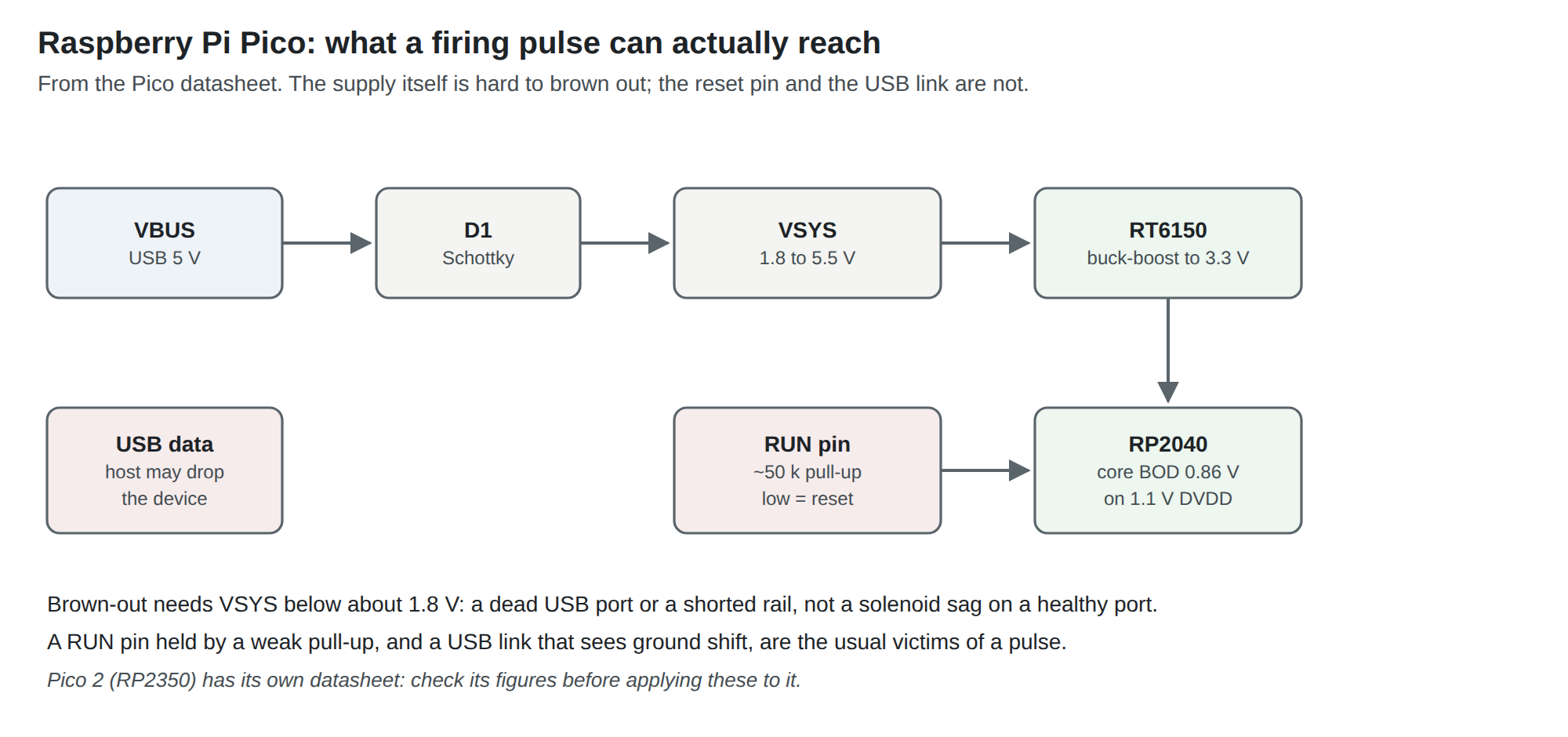
The Raspberry Pi Pico is unusually hard to brown out. Its datasheet gives the VSYS input range as 1.8 V to 5.5 V, feeding an RT6150 buck-boost regulator that produces 3.3 V across that whole range.2 Inside the RP2040, the brown-out detector watches the digital core supply, DVDD (nominally 1.1 V), and resets the chip only if DVDD falls below a threshold that defaults to 0.86 V.3 For a supply-driven reset, then, VSYS must fall below about 1.8 V, far enough that the buck-boost can no longer hold 3.3 V and the core regulator behind it drops out.
A USB port’s 5 V does not sag to 1.8 V because a solenoid on a separate supply fired. It reaches that level only if the port is switched off altogether, which a host does when its over-current protection acts, or if the gun’s own 5 V and the solenoid’s supply are connected, so that the coil’s pulse is drawn from the USB port (Vol 3, section 3.4).
So when a Pico “resets when firing” on a correctly separated supply, one of these is usually the real cause:
- The USB link drops. The host sees a disturbance on the data lines or the ground, abandons the device, and re-enumerates it. To the user this looks exactly like a reset; the firmware may never have stopped running.
- The RUN pin is pulled low. RUN is held high by an on-chip pull-up of about 50 kΩ, and shorting it low resets the chip.2 A weak pull-up on a pin routed anywhere near the solenoid’s current loop, or a RUN wire run to a reset button alongside the solenoid leads, can be pulled low by coupled noise for long enough to act.
- The camera’s I2C link hangs. A ground shift or a noise spike corrupts an I2C transaction, the camera stops answering, and the tracking freezes while the board is still running. Whether and how the firmware recovers is a question for the Open-Source Firmware dive; from the outside it looks like a fault in the gun.
- A genuine supply collapse, because the solenoid supply and USB 5 V are joined, or because the host has cut the port.
Only the fourth is cured by a bigger capacitor. The first three are cured by controlling where the solenoid’s current flows.
5.3 Where the Return Current Goes
Every amp that leaves the brick’s positive terminal returns to its negative terminal by some path. The builder controls which.
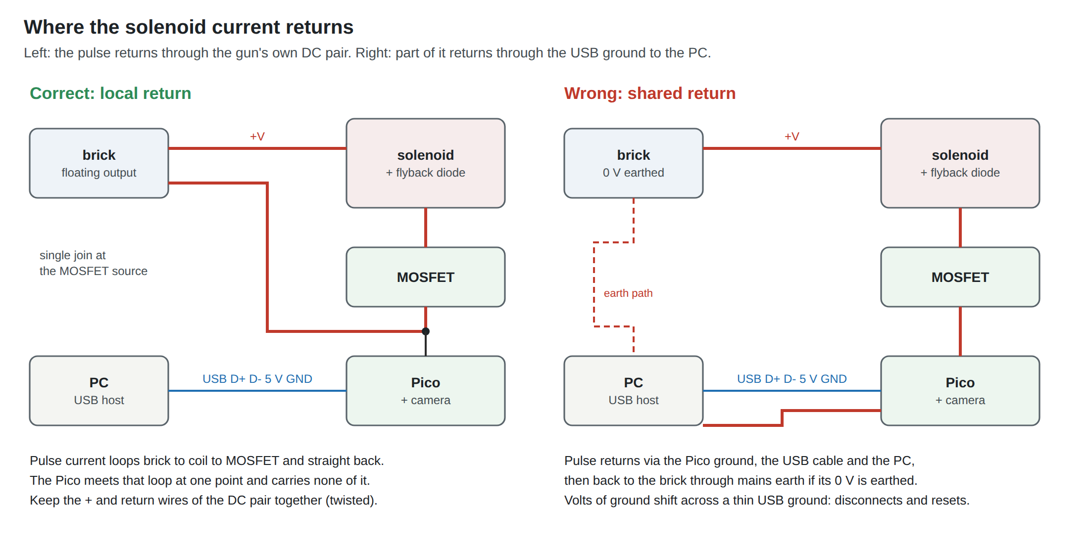
Both driver boards linked from the OpenFIRE and GUN4IR world tell the builder to land the supply ground and the microcontroller ground on the same pad.45 That is the single join shown on the left of the diagram, and it is correct. The common ground is necessary, because the MOSFET’s gate is driven relative to the microcontroller’s ground. What matters is that the join is a point: the pulse current must have its own return path to the brick, and the logic ground must meet that path in one place, not share a length of it.
The commonest ways builds end up on the right of the diagram:
- Returning the solenoid through the board. The coil’s MOSFET is on the main board and its source pad is tied to the board’s ground plane, and the DC supply’s negative wire lands somewhere else on the same plane. The pulse crosses the plane and every ground-referenced signal on the board moves with it.
- Routing the DC supply through the USB cable. A gun with one cable to the PC, carrying both USB and the solenoid supply as AimTrak does, can share the return conductor between the two, or use the cable shield as one of them.6 A shared return carries the pulse current and the USB ground together.
- Earthing at both ends. If the brick’s 0 V is connected to mains earth and the PC’s is too, a second return path exists through the house wiring. Some of the pulse current takes it, through the USB ground.
5.4 The OpenFIRE Wire-Gauge Note: Right Advice, Doubtful Reason
OpenFIRE’s README carries one power note:
“Solenoid may cause EMI disconnects with too thin of wiring. Cables for this run specifically should be 24AWG at its thinnest - or else the cables will become antennas under extended use, which will trip USB safety thresholds in your PC to protect the ports.”7
The advice is sound and the symptom it describes is real. The explanation is doubtful. Wire gauge has very little effect on how well a conductor radiates or picks up interference at the frequencies involved; a thin wire is not appreciably more of an antenna than a thick one of the same length and routing. What wire gauge does change, strongly, is resistance, and resistance in a shared return path is ground shift.
The arithmetic from Vol 2 makes the point. A single 28 AWG conductor 5 m long is about 1.06 Ω. If it is the shared ground for USB and a 2 A solenoid, the gun’s ground rises about 2.1 V above the PC’s during every pulse. At 24 AWG the same run is 0.42 Ω and 0.84 V; at 20 AWG it is 0.17 Ω and 0.33 V. A ground offset of volts between a USB device and its host is far outside what USB’s signalling is designed to tolerate, and the host may treat the resulting errors as a failed device. Separately, if the host’s VBUS protection sees its port’s current spike or its voltage disturbed, it may shut the port off.
Thicker wire therefore does help, by lowering the shared resistance, which is exactly what the README recommends. The more complete fix is to stop sharing: give the solenoid its own supply pair, return it to the brick on that pair, and join the logic ground at one point. With no pulse current in the USB ground, the gauge of the USB cable stops mattering, and 24 AWG becomes a voltage-drop question for the solenoid pair alone, answered in Vol 2’s table.
5.5 Earthed and Floating Bricks
Whether a brick’s 0 V is tied to mains earth decides whether the third path exists. Mean Well’s datasheets say so explicitly. The GST60A and GST90A, despite their three-pin IEC C14 inlets, carry the note “-V not connected to AC FG”: their output floats.89 The GST120A in its four-pin DIN version is the opposite: “-V connected to AC FG.”10
A desktop PC’s 0 V is almost always tied to earth through its power supply and chassis. A gun fed from an earthed brick and plugged into an earthed PC therefore has two returns for its solenoid pulse: the DC pair, and the USB ground through the PC’s chassis, the house wiring, and back into the brick. How the current divides depends on the resistances, but some of it will take the USB route.
For a light gun, a floating brick is the better choice, and a desktop brick with a two-pin inlet, or a three-pin one whose datasheet confirms that the output is not earthed, should be preferred. A laptop or a Raspberry Pi running from its own floating supply removes the question from the host end.
5.6 The Flyback Clamp and the Supply Rail
When the MOSFET turns off, the coil’s current has to go somewhere. Without a clamp, the drain voltage rises until something breaks down, usually the MOSFET in avalanche, and the edge is fast and large enough to couple through the MOSFET’s drain-gate capacitance into its gate drive and onward into the GPIO, and to radiate. The flyback diode across the coil prevents this, and both OSH Park driver boards show one.45 The diode’s effect on release time, and the faster-release alternatives with a Zener or TVS in series, belong to the Solenoid Recoil dive. Three supply-side points belong here.
A missing or open flyback diode is a noise source before it is a reliability problem. A gun that resets only on the release of each shot, not the start, points to the turn-off edge: check the diode first.
Energy returned to the supply rail. With a plain diode across the coil, the stored energy circulates in the coil and diode and is dissipated there. With faster-release schemes that steer the energy back to the supply rail, a brick cannot absorb it (it is not designed to sink current), and the rail rises. The GST60A24’s over-voltage protection is specified at 25.2 to 32.4 V and it shuts down and must be re-powered to recover.8 A bank, by contrast, simply absorbs the energy. A design that returns energy to the rail needs either a bank or a clamp on the rail.
A TVS on the supply input catches what the brick, the cable and a hot-plug event can put on the rail. For a 24 V input, a 600 W SMB part with a 28 V stand-off is the usual choice; ST lists its SMBJ28A at 600 W for a 10/1000 µs pulse, and distributor listings for the same type give about 45 V maximum clamping at its rated pulse current.11 It protects the board from transients; it is not a flyback clamp and should not be relied on as one. The choice is the SMBJ28A (D33, 19 October 2026). The rail is 24 V nominal with an 18 to 28 V working window (Solenoid Recoil Vol 8), so the 28 V stand-off sits exactly at the top of the window: at its stand-off a TVS passes only leakage, and it begins to conduct in earnest at its breakdown voltage, above the window. The deciding number is the other end. The Reference Electronics board’s regulated driver, the DRV8251A, is rated 50 V absolute maximum. The SMBJ28A clamps at about 45 V at its rated current; the SMBJ33A, the earlier pick (33 V stand-off, 53.3 V clamping at 11.3 A), does not stay under 50 V when driven that hard. The SMBJ33A remains on the board as the discrete stage’s drain clamp, a different job. A 12 V rail wants a correspondingly lower stand-off from the same family’s datasheet.
5.7 Layout Inside the Gun
The Reference Electronics dive owns the schematic and the board. The supply-side rules it needs to satisfy are few:
- Make the pulse loop small and separate. Supply positive, coil, MOSFET, sense resistor if any, and supply negative should form the tightest loop the shell allows, with the DC pair twisted all the way to the connector. The area of that loop is what radiates and what picks up.
- One join between pulse ground and logic ground, at the MOSFET’s source or the supply connector’s negative, and nowhere else.
- A local reservoir at the driver. A few hundred microfarads of low-ESR capacitance at the point where the DC pair enters the gun supplies the fast edges of the pulse locally, so that the cable carries a smoother current. This is the capacitor the builder brief recommends, and it is useful for this reason, not because it holds up the Pico.
- Gate drive. A series gate resistor slows the edges a little (the OSH Park board’s 1 kΩ appears to serve this purpose), and a pull-down holds the gate low through boot (its 100 kΩ appears to be that).4 The resistors’ functions are read from the silkscreen; the board publishes no schematic.
- Keep the RUN pin and the I2C lines away from the pulse loop. RUN’s 50 kΩ internal pull-up is weak; a short trace, a ground-referenced reset button wired close to the board, and if necessary a small capacitor from RUN to ground make it harder to disturb. The I2C run to the camera at the muzzle is often the longest signal in the gun and runs past the solenoid; twisting SDA and SCL each with a ground, and using pull-ups no weaker than the camera’s documentation requires, reduces its exposure.
- Keep the solenoid’s supply away from the logic’s. The Pico and camera run from USB 5 V; the coil runs from its own supply. Joining the two, even through a diode, invites the coil to draw from USB when its own supply is absent or tripped.
5.8 Ferrites, TVS Diodes and What They Will Not Fix
Ferrite clamps on the USB cable are a common first remedy. They suppress common-mode noise at high frequencies, which can help with radiated coupling into the USB pair. They do nothing about a ground shift caused by pulse current in a shared return: that is a low-frequency, differential voltage across a resistance, and ferrite does not change resistance.
Ferrite beads in series with the solenoid supply are a mistake. A bead small enough to fit carries its impedance only at low current; a few amps of pulse current saturate it, and its inductance then adds to the turn-off overshoot. Put ferrites on the USB and the logic lines, not in the pulse path.
ESD and transient protection on the USB connector, a low-capacitance TVS array across D+ and D− and VBUS, protects against a player’s static discharge and is good practice for any product that might be sold. It is not a cure for firing-induced disconnects.
5.9 Diagnosis Table
Table 1 — Diagnosis Table
| Symptom | Most likely cause | Check |
|---|---|---|
| PC plays the disconnect sound when the coil fires; gun re-enumerates | Ground shift on the USB link from shared return current; or host port over-current | Scope the difference between gun ground and host ground during a pulse; check whether the coil’s supply is joined to VBUS |
| Gun reboots only at the moment of release, not at the start of the pulse | Turn-off transient: flyback diode missing, reversed or open | Inspect and measure the diode; scope the drain voltage at turn-off |
| Gun reboots at the start of the pulse | Coil drawing from USB 5 V; or RUN pin coupled to the pulse loop | Check for any connection between coil supply and VBUS or VSYS; scope RUN during a pulse |
| Cursor freezes but buttons still work | Camera I2C hung | Scope SDA and SCL during a pulse; check the camera’s ground return |
| Recoil works on single shots, stops in autofire, comes back after a second | Brick in hiccup (Vol 2) | Scope the brick’s output during a burst |
| Recoil weakens steadily in autofire and recovers slowly | Bank and charge rate (Vol 3, Vol 4), working as designed | Scope the bank voltage during a burst |
| Fault appears only with one particular brick | Earthed brick on an earthed host; or a brick near its trip | Read the brick’s datasheet for its -V to FG note; try a floating brick |
5.10 Measuring It Without Creating a New Ground Loop
The lab’s Analog Discovery Pro ADP3450 and Analog Discovery 2 are the right instruments for every check in the table, with one trap. Their inputs are referenced to their own ground, which is the ground of the computer they are plugged into by USB. Clip a probe ground to the gun while the gun is plugged into a different PC, and the instrument has added a ground path between the two machines: the measurement changes the fault.
Three ways round it:
- Measure on one PC. Plug the gun and the instrument into the same computer, so their grounds are already common, and keep the probe ground leads short and at the gun’s single ground join.
- Measure differentially. Use two channels referenced to the same point and subtract them in software (WaveForms’ math channel), for example the gun’s ground and the host’s USB shell, to see the ground shift without clipping a ground lead to anything else.
- Isolate the host side. Run the instrument from a laptop on battery, which removes its earth.
The first measurement worth making on any new build is the ground shift between the Pico’s ground and the host’s USB ground during a pulse. If it is a few tens of millivolts, the grounding is right and any remaining fault is elsewhere. If it is volts, nothing else on the bench matters until it is fixed.
Footnotes
-
The OpenFIRE build guide that started this category (Michael’s brief, 2024 forum-sourced), troubleshooting table: “Pico resets when firing: Solenoid supply is leaking into the Pico supply. Separate the supplies and add a capacitor across the solenoid supply.” Held in the Open-Source Firmware dive’s working files. ↩
-
Raspberry Pi Ltd, Raspberry Pi Pico Datasheet, VSYS range, power-supply description and RUN pin. https://datasheets.raspberrypi.com/pico/pico-datasheet.pdf (downloaded 2026-10-18). ↩ ↩2
-
Raspberry Pi Ltd, RP2040 Datasheet, §2.12.2 “Power-on Reset” (DVDD threshold 0.957 V nominal) and §2.12.3 “Brown-out Detection” (default threshold 0.86 V). https://datasheets.raspberrypi.com/rp2040/rp2040-datasheet.pdf (downloaded 2026-10-18). ↩
-
Prozac4545, “Gun4IR_Solenoid v1.1,” OSH Park: “the Arduino and solenoid must share a common ground”; “You’ll need to piggyback the power ground and Arduino onto the same pad.” https://oshpark.com/shared_projects/bjY4d7Vo (accessed 2026-10-18). ↩ ↩2 ↩3
-
drbogger, “GUN4IR Rumble & Solenoid,” OSH Park: “the Arduino and power supply must share a common ground.” https://oshpark.com/shared_projects/yC6D11ud (accessed 2026-10-18). ↩ ↩2
-
Ultimarc, “AimTrak Light Gun With Recoil”: “The recoil power is routed via the connecting cable.” https://www.ultimarc.com/light-guns/aimtrak-light-gun/aimtrak-light-gun-with-recoil/ (accessed 2026-10-18). ↩
-
TeamOpenFIRE, OpenFIRE-Firmware,
README.md, NOTE at the end of “TODO,” commit 8b651a2 (19 April 2026). https://github.com/TeamOpenFIRE/OpenFIRE-Firmware (accessed 2026-10-18). ↩ -
Mean Well, GST60A series specification, file GST60A-SPEC 2026-04-03 (pin assignment: “-V not connected to AC FG”; over-voltage protection). https://www.meanwell.com/Upload/PDF/GST60A/GST60A-SPEC.PDF (downloaded 2026-10-18). ↩ ↩2
-
Mean Well, GST90A series specification, file GST90A-SPEC 2026-04-03. https://www.meanwell.com/Upload/PDF/GST90A/GST90A-SPEC.PDF (downloaded 2026-10-18). ↩
-
Mean Well, GST120A series specification, file GST120A-SPEC 2025-03-28 (four-pin DIN pin assignment: “-V connected to AC FG”). https://www.meanwell.com/Upload/PDF/GST120A/GST120A-SPEC.PDF (downloaded 2026-10-18). ↩
-
STMicroelectronics, SMBJ28A product page (600 W, 10/1000 µs, 28 V stand-off). https://www.st.com/en/protections-and-emi-filters/smbj28a.html (accessed 2026-10-18). The 45.4 V maximum clamping figure is from distributor listings of the Bourns part; confirm against the chosen maker’s datasheet. ↩
Comments (0)