LiPo Batteries · Volume 4
Protection — Fuse, Pack Protector, Rail Switch and Temperature
A hobby pack has none of its own. What sits between a 6S pack and the 24 V rail, what each part answers, and which parts: a DC fuse, two stacked BQ77905 protectors, an LM5060 soft-start switch, a thermistor and a fuel gauge that does not drain the pack on the shelf
4.1 Why the Gun Carries the Protection
A phone or laptop battery has its protection inside the pack: a protector IC and a pair of switches that open on over-voltage, under-voltage, over-current and short circuit. An RC hobby pack has none of that. It is cells, a wrap, a main lead and a balance lead, and its makers assume a flight controller and an external charger will look after it. A gun that takes a hobby pack must therefore carry the protection itself.
On a brick, the brick is part of the protection. Its trip band limits a fault to a few amps (Power Supplies Vol 2), and Ultimarc’s AimTrak relies on exactly that (Power Supplies Vol 1). A pack’s prospective short-circuit current is of the order of 150 A (Volume 3). The carrier’s own parts (F1 on V_SOL, the SMBJ28A, the bulk capacitor, the DRV8251A’s 4.1 A trip) were chosen for a brick, and the battery-side chain below is added in front of them, not instead of them (Reference Electronics Vol 8).
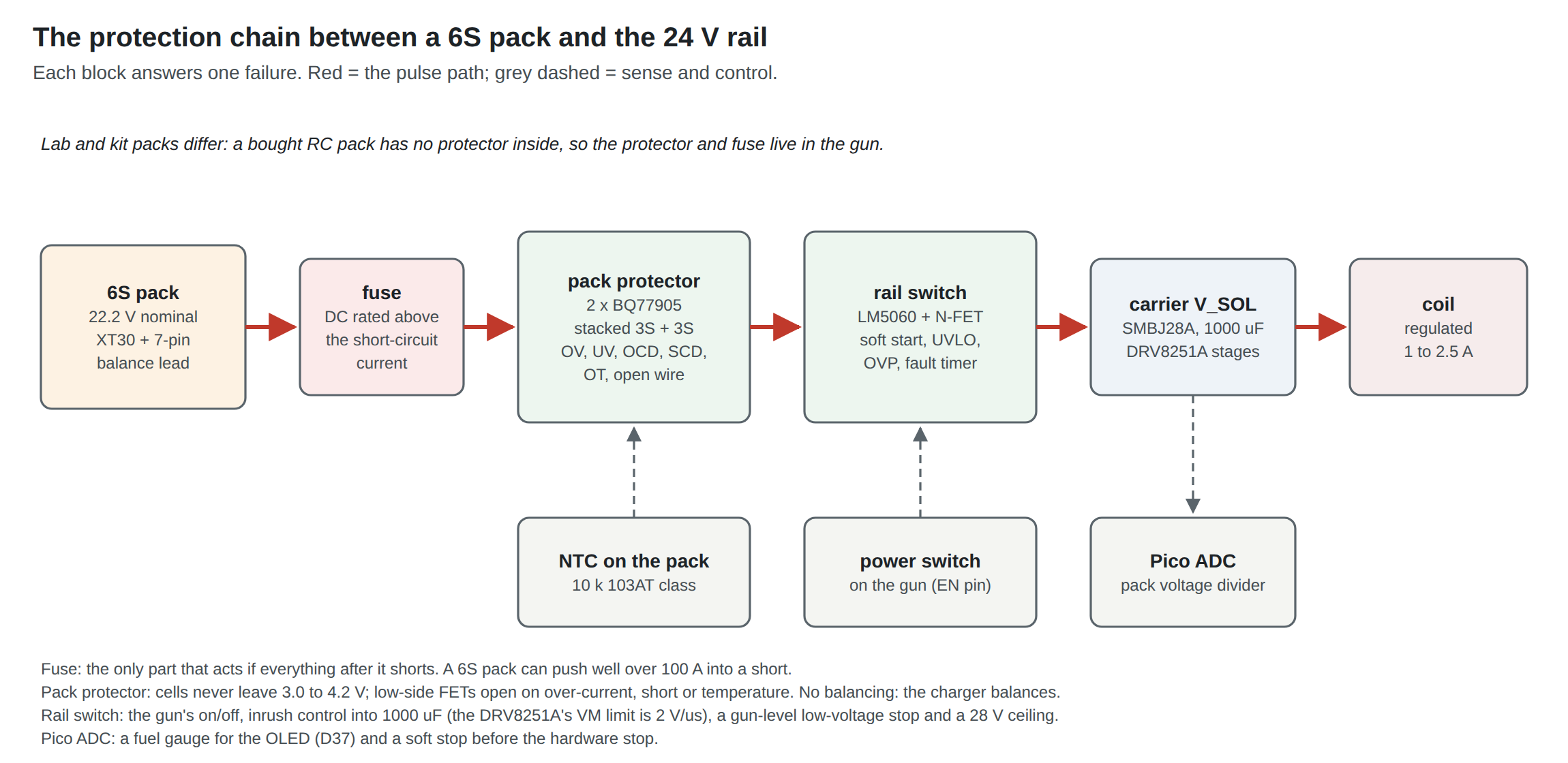
4.2 The Chain in One Diagram
Each block answers one failure:
Table 1 — Each block answers one failure
| Failure | Block that stops it | Backed up by |
|---|---|---|
| Short circuit in the wiring or the carrier | Fuse | Protector short-circuit trip |
| Cell over-discharge | Protector under-voltage | Rail switch UVLO; firmware stop |
| Cell over-charge (charger fault) | Protector over-voltage | Charger’s own limit |
| Over-current that is not a short | Protector over-current | DRV8251A trip (per stage) |
| Pack too hot or too cold | Protector over/under-temperature | Firmware, from the coil sensor |
| Inrush into 1000 µF when the pack connects | Rail switch soft start | — |
| Wrong pack (7S, wrong chemistry setting) | Rail switch over-voltage | SMBJ28A |
| Gun left on | Firmware sleep; rail switch off | Protector under-voltage |
4.3 The Fuse
The fuse is the only part in the chain that does not depend on a working chip. It belongs at the pack’s positive lead, as close to the pack as the build allows, so that it protects the wire between the pack and the carrier, which is the part most likely to be pinched by a printed shell closing on it.
What it must do:
- Carry the working current without ageing. The steady current is under about 2 A and the pulse peaks at the set point, 2.5 A at most, for tens of milliseconds several times a second (Volume 3). A fuse’s time-current curve and its pulse-derating guidance, from its own data sheet, decide the rating; on these numbers something in the 5 A class is the starting point, to be checked against the bench’s measured RMS current.
- Be rated for DC at above the pack voltage. A full 6S pack is 25.2 V and the regen rise can briefly take the rail to about 27.5 V (Volume 2). Many small fuses carry only an AC rating or a 24 V or 32 V DC rating; the DC rating is the one that counts, because a DC arc does not self-extinguish at a current zero.
- Interrupt the prospective fault current. The interrupting rating must exceed the pack’s short-circuit current at the fuse’s DC voltage rating. Volume 3’s estimate is about 150 to 170 A for a 6S1P cylinder pack. A small pouch pack’s figure is not published, and the bench should not try to measure it. The fuse is chosen with its interrupting rating comfortably above the estimate.
No fuse part number is proposed here: the carrier’s F1 is still “value from one stage’s measured peak” (Reference Electronics Vol 9), and the pack fuse is picked from the same bench measurement (Volume 7, test B2), against the three criteria above, from a maker’s data sheet. A common in-line choice in hobby packs is an automotive blade fuse in a holder; whether a particular blade family’s DC voltage and interrupting ratings meet the criteria is checked on its maker’s sheet, not assumed.
4.4 The Pack Protector
A protector IC watches each cell and opens a pair of MOSFETs when a limit is crossed. Three classes of TI part were read for this dive, and they differ in a way that matters:
Table 2 — A protector IC watches each cell and opens a pair of MOSFETs when a limit is crossed. Three classes of TI part were read for this dive, and they differ in a way that matters
| Part | Class | Cells | What it does alone | Needs a host? | FETs | Balancing |
|---|---|---|---|---|---|---|
| BQ77905 | Stackable protector | 3–5 per device, stack for more | OV (3–4.575 V), UV (1.2–3 V), two discharge over-current levels, short circuit, over- and under-temperature in charge and discharge, open wire | No: “without microcontroller (MCU) control” | Low-side CHG and DSG N-FETs | Not listed |
| BQ76930 | Monitor with hardware protection | 6–10 | OV, UV, discharge over-current, short circuit in hardware | Yes, over I²C, for pack management | Drivers for external FETs | Integrated balancing FETs |
| BQ76952 | Monitor and protector | 3–16 | Voltage, temperature, current (charge and discharge), short circuit, diagnostics | Configurable; the product page describes autonomous options but does not say it runs fully standalone | High-side N-FETs from a charge pump | Autonomous or host-controlled |
From TI’s product pages, read 19 October 2026.123
The pick for the first battery build: two BQ77905, stacked 3S + 3S. It is the only one of the three that protects with no software at all. That matters in a gun whose microcontroller is a hobby board running an open firmware being forked (D10): if the Pico is unpowered, crashed or being reflashed, the cells are still protected. Its thresholds are set by part variant and external components, not by a configuration that could be lost. Its quiescent current is 6 µA typical, 0.5 µA in shutdown, which suits a pack left in a gun.1
What it does not do: balance. The external charger balances every cell on every charge through the balance lead (Volume 5). A pack charged only through its main leads, as an on-board charger would, needs balancing added, and that is the point at which the BQ76952 or the BQ76930 earns its place (Volume 5).
What it costs: a board. Two TSSOP-20 devices, two MOSFETs, a sense resistor, a thermistor and a dozen passives. That is a small four-layer or two-layer board Jeff can lay out in Altium alongside the carrier, or a section of the carrier itself. Its design follows the BQ77904/BQ77905 data sheet’s stacked application circuit (Rev. K, 31 July 2020), which this dive cites but does not reproduce.
Ready-made boards. Marketplaces sell “6S BMS” boards for a few dollars, usually with balancing and a 15 to 40 A rating, aimed at 18650 packs. They have no data sheet that states their thresholds, the identity of their IC is often unknown, and their over-current trip is far above anything this gun should ever draw. They are acceptable on the bench to protect a test pack; they are not acceptable in a kit (Volume 7, and decision D8’s “legally clean” products).
4.5 Low-Side or High-Side Switching
The BQ77905 opens the pack’s negative lead. When it trips, the pack’s negative terminal separates from the gun’s ground, and pack positive stays connected to V_SOL. Nothing flows, because every load returns through the open switch. But two things follow:
- Any second connection between pack negative and gun ground is a sneak path around the protector. The balance lead’s negative pin, a scope ground clipped to the pack, a charger connected to the balance lead while the gun’s USB cable is plugged into a PC: each can bypass the open switch. The rule is simple and goes in the build notes: nothing touches pack negative except through the protector, and the balance lead is never connected while the gun is connected to anything else.
- The regen energy cannot enter the pack while the charge switch is open. The protector opens CHG at over-voltage, which is the state of a freshly charged pack. The bulk capacitor then takes the coil’s returned energy, and Volume 2 shows that lands at about 27.5 V from a full pack: inside the window, by half a volt.
High-side switching (the BQ76952’s charge pump) avoids the first point: pack negative and gun ground stay permanently common. That is the more robust arrangement for the wireless-power-only build, where the USB cable ties the gun’s ground to a PC’s. It is the step up if the bench shows a sneak path is easy to create in practice.
4.6 Temperature
The BQ77905 reads a thermistor and has separate over- and under-temperature limits for charge and discharge.1 The thermistor is taped to the pack’s largest face, under the wrap if the pack is rewrapped, not on the protector board.
The limits that matter are the cells’ own. Molicel gives 0 to 60 °C for charge and −40 to 60 °C for discharge for the P28A;4 hobby LiPo packs rarely publish one. Below freezing, lithium cells must not be charged at all. The printed gun adds a hotter neighbour: a working solenoid coil, on which OpenFIRE warns at 38 °C and stops at 45 °C on the frame, with the winding hotter than its surface (Solenoid Recoil Vol 4). Volume 6 deals with keeping the pack away from it; the protector’s discharge over-temperature limit is the hardware backstop if that fails.
4.7 The Rail Switch: Inrush, Under-Voltage, Over-Voltage
Connecting a charged pack to a board with 1000 µF across its input is a hot plug at 25 V into a near short. The carrier was designed around a brick that rises on its own start-up after the GX plug is mated (D31). A pack has no start-up: it is either connected or not. The DRV8251A’s data sheet limits how fast its supply may rise, to 2 V/µs (Reference Electronics Vol 5), and a pack mated on an XT30 can exceed that, with a spark at the connector to match.
The answer is a high-side protection controller with a controlled rise. TI’s LM5060 is a good fit on its product page’s own terms:5
- 5.5 to 65 V operating, 75 V absolute maximum: the whole window and every fault above it.
- A charge-pump gate drive for an external N-channel MOSFET. The 60 V IPD50N06S4L-12 already in the Reference Electronics BOM for the discrete stage (12 mΩ at 10 V) is a candidate; at 2.5 A it dissipates 0.08 W at its 12 mΩ (10 V gate) maximum and 0.14 W at its 21.6 mΩ (4.5 V gate) maximum.
- A nearly constant output rise time, which sets the inrush. Charging 1000 µF to 25 V in 10 ms is a slope of 2.5 V/ms, nearly a thousand times under the DRV8251A’s limit, and an inrush of C·dV/dt = 2.5 A, no more than one shot. In 5 ms it is 5 A.
- Adjustable under-voltage lockout with hysteresis, which becomes the gun’s hardware low-voltage stop (about 19.5 V falling; Volume 2, 2.9), and an enable path, so the gun’s power switch drives a logic input instead of carrying the coil current.
- Adjustable over-voltage protection, set at 28 V: a 7S pack or a charger left on the wrong setting is refused before the TVS has to act.
- A fault timer that latches the MOSFET off if an over-current persists.
The product page notes that a newer version exists; the newer part is worth checking at layout time.5 The rail switch is not a substitute for the fuse: it relies on its own sensing and a working MOSFET, and a shorted MOSFET passes the fault straight through.
Reverse polarity. XT30 and the JST-XH balance plug are both keyed, so a reversed pack needs a mis-crimped lead. The LM5060 does not block reverse voltage, and the DRV8251A and SMBJ28A would conduct. A kit should ship packs already terminated and tested. A bench build should check every new lead with a meter before first connection.
4.8 A Fuel Gauge That Does Not Drain the Pack
The firmware’s warning and stop thresholds (Volume 2, 2.9) need the pack voltage on a Pico ADC pin. A divider from 25.2 V to under 3.3 V is the obvious way, and it has an obvious cost: it is a permanent load on the pack.
Table 3 — 4.8 A Fuel Gauge That Does Not Drain the Pack
| Divider | Ratio | 25.2 V reads | Current | Drain per day | Days to take 10 % of a 450 mAh pack |
|---|---|---|---|---|---|
| 100 kΩ over 10 kΩ, on the pack side | 1/11 | 2.29 V | 0.23 mA | 5.5 mAh | 8 |
| 1 MΩ over 100 kΩ, on the pack side | 1/11 | 2.29 V | 23 µA | 0.55 mAh | 82 |
| Either, after the rail switch | 1/11 | 2.29 V | zero when off | — | — |
Arithmetic from the resistor values. Put the divider after the rail switch so that it draws nothing when the gun is off, and use the higher values with a 100 nF capacitor at the ADC pin so the Pico’s sample-and-hold sees a low source impedance. Read it between shots, as Volume 3 says.
Every other always-on load on the pack side adds to the shelf drain: the protector’s 6 µA, the LM5060’s own quiescent current, a buck regulator’s 0.1 mA if it sits before the switch (Volume 3). The sum, not just the divider, decides whether a gun can be left with its pack connected. Volume 6 says it should not be.
4.9 Why This, and Why Not the Others
Table 4 — 4.9 Why This, and Why Not the Others
| Choice | Picked | Rejected | Why, and why not |
|---|---|---|---|
| Short-circuit protection | In-line DC fuse at the pack’s positive lead, rated from the bench current (Volume 7) | Relying on the protector’s short-circuit trip; relying on F1 on the carrier | The fuse is the one part that needs no working chip and protects the pack lead itself; F1 sits after the lead and was sized for a brick |
| Pack protector | Two BQ77905, stacked 3S + 3S (proposed, bench-trial first) | BQ76930; BQ76952; marketplace 6S BMS boards; none (charger only) | Only the BQ77905 protects with no host and no configuration, at 6 µA; BQ76930 needs a host for pack management; BQ76952 is the step up for high-side switching and balancing; marketplace boards have no data sheet and trip at 15–40 A; none leaves a hobby pack unprotected in the gun |
| Switching side | Low-side (BQ77905), with a “nothing touches pack negative” rule | High-side (BQ76952) | Low-side is the standalone part’s architecture; high-side is adopted if the bench shows a sneak path is easy in the wireless-power-only build |
| Rail switch | LM5060 + 60 V N-MOSFET (IPD50N06S4L-12 candidate) | Hot-plugging the pack onto V_SOL; an anti-spark connector alone; a P-MOSFET with an RC gate | Gives soft start under the DRV8251A’s 2 V/µs, a hardware UVLO, a 28 V OVP and a fault latch in one part; an anti-spark plug only handles the first contact; a P-FET soft start has no UVLO or OVP |
| Power switch | Logic switch on the rail switch’s enable | Switch in series with the pack | A logic switch carries microamps; a series switch carries the pulse and arcs |
| Temperature | NTC on the pack face, read by the protector | No sensor; sensor on the protector board | The cells are what overheat; the board can be cool while the pack is not |
| Fuel gauge | 1 MΩ / 100 kΩ divider after the rail switch, read between shots | 100 kΩ / 10 kΩ on the pack side; a fuel-gauge IC | Zero drain when off; a coulomb-counting gauge is more than a light gun needs |
Footnotes
-
Texas Instruments, BQ77905 product page, “3- to 5-series li-ion and li-phosphate ultra-low-power stackable battery protector”; data sheet BQ77904, BQ77905 3-Series to 20-Series Ultra Low-Power Voltage, Current, Temperature, and Open-Wire Stackable Lithium-Ion Battery Protector, Rev. K, 31 July 2020. https://www.ti.com/product/BQ77905 (read 2026-10-19). ↩ ↩2 ↩3
-
Texas Instruments, BQ76930 product page, “6 to 10-Series Cell Li-Ion and Li-Phosphate Battery Monitor (bq76940 Family)”; data sheet BQ769x0, Rev. I, 14 March 2022. https://www.ti.com/product/BQ76930 (read 2026-10-19). ↩
-
Texas Instruments, BQ76952 product page, “3-Series to 16-Series High Accuracy Battery Monitor and Protector for Li-Ion, Li-Polymer, and LiFePO4 Battery Packs”, data sheet Rev. B, 15 November 2021. https://www.ti.com/product/BQ76952 (read 2026-10-19). ↩
-
Molicel, Product Data Sheet, INR-18650-P28A, copy at https://www.rosebatteries.com/hubfs/INR18650P28A-V2-80093.pdf (read 2026-10-19). ↩
-
Texas Instruments, LM5060 product page, “High-Side Protection Controller With Low Quiescent Current”, data sheet Rev. H, 23 December 2019. https://www.ti.com/product/LM5060 (read 2026-10-19). ↩ ↩2
Comments (0)