LiPo Batteries · Volume 2
Cell Count Against the 24 V-Class Rail
Does a 6S pack sit inside 18 to 28 V? 5S, 6S and 7S LiPo, LiHV, 6S Li-ion, 7S and 8S LiFePO4, and the case for a smaller pack behind a boost converter
2.1 Where the 18 to 28 V Window Comes From
Decision D14 fixed the recoil rail at “24 V class, 18–28 V working”. The reasoning is in Solenoid Recoil Vol 8, and it already names the pack: the rail “accepts the three supplies the project is likely to use: a 24 V brick, a 20 V USB PD contract at somewhat reduced forcing, and a 6S pack”. That volume’s table lists the matching pack for each rail voltage (3S for 12 V, 5S for 20 V, 6S for 24 V). This volume does not repeat the rail argument; it tests the packs against the window in detail, because the window has two edges with different causes.
The floor, 18 V, is a forcing-ratio floor. Under the regulated stage (D13), the rail voltage is no longer the kick setting; it is the headroom that lets the coil current reach its set point quickly when the coil is hot. Solenoid Recoil Vol 8 picks coils whose hot I·R is about half the rail, so that the forcing ratio V/(I·R) is near two at 24 V. At 18 V the same coil has a forcing ratio near 1.5, which that volume treats as the lower working limit. Below it, the current rises slowly and a hot coil may never reach the set point, and the kick fades.
The ceiling, 28 V, is a protection ceiling. The carrier’s input TVS is an SMBJ28A (D33), whose 28 V stand-off “equals the top of the 18–28 V window” (Reference Electronics Vol 5). Stand-off is the voltage at which the diode’s leakage is specified to stay small; above it the diode starts to conduct as it approaches breakdown. The DRV8251A itself runs to 48 V with a 50 V absolute maximum, so the driver is not the ceiling; the clamp is.
A pack must therefore stay above 18 V when nearly flat and under load, and below 28 V when freshly charged and while the coil is returning energy to the rail.
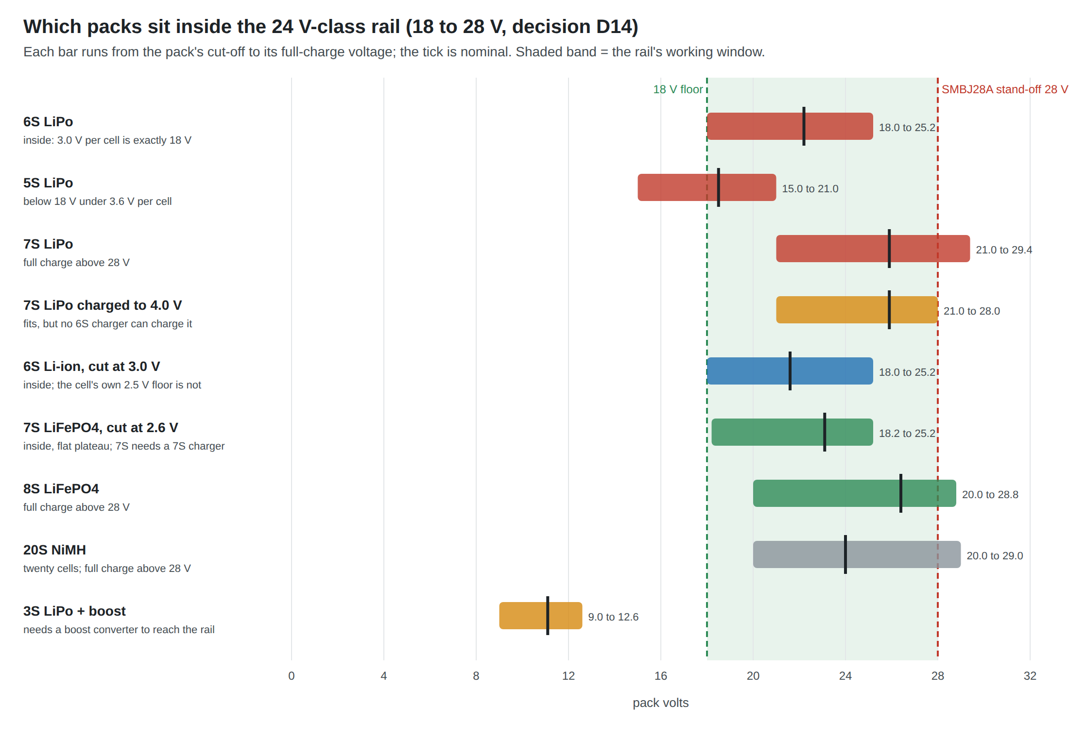
2.2 Every Candidate on One Chart
Table 1 — 2.2 Every Candidate on One Chart
| Pack | Full | Nominal | Cut-off | Inside 18–28 V? | Per-cell voltage at 18 V |
|---|---|---|---|---|---|
| 6S LiPo | 25.2 V | 22.2 V | 18.0 V at 3.0 V/cell | Yes, exactly | 3.00 V |
| 5S LiPo | 21.0 V | 18.5 V | 15.0 V | No: below 18 V under 3.6 V/cell | 3.60 V |
| 7S LiPo | 29.4 V | 25.9 V | 21.0 V | No: above 28 V when full | 2.57 V |
| 7S LiPo, charged to 4.0 V/cell | 28.0 V | 25.9 V | 21.0 V | Only just, and see 2.5 | — |
| 6S LiHV (4.35 V/cell) | 26.1 V | 22.8 V | 18.0 V at 3.0 V/cell | Yes | 3.00 V |
| 6S Li-ion (P28A) | 25.2 V | 21.6 V | 15.0 V at the cell’s 2.5 V | Only if the gun stops it at 3.0 V/cell | 3.00 V |
| 7S LiFePO4 | 25.2 V | 23.1 V | 17.5 V at 2.5 V/cell | Yes if stopped at 2.6 V/cell (18.2 V) | 2.57 V |
| 8S LiFePO4 | 28.8 V | 26.4 V | 20.0 V | No: above 28 V when full (unless charged to 3.5 V/cell) | 2.25 V |
| 20S NiMH | about 29 V | 24 V | about 20 V | No, and twenty cells | — |
| 3S LiPo | 12.6 V | 11.1 V | 9.0 V | No: needs a boost converter | — |
Cell figures are from Volume 1; arithmetic in 04-templates/battery_calcs.py.
2.3 6S LiPo: the Pack the Rail Was Drawn Around
Six LiPo cells span 18.0 to 25.2 V. Both edges are inside the window, and two of the margins deserve a closer look.
At the top: the regen rise. A fresh pack at 25.2 V is 2.8 V below the ceiling. Normally the pack absorbs the coil’s returned energy and its terminal voltage barely moves. If the pack protector has opened its charge switch (it does so when any cell reaches its over-voltage threshold, which is exactly when the pack is full; Volume 4), the energy goes into the carrier’s 1000 µF bulk capacitor instead. The Reference Electronics volume puts the energy at about 0.06 J and the rise at about 2.5 V; starting from 25.2 V the capacitor reaches about 27.5 V, still under 28 V. The margin is half a volt. It holds for the coil model in the sibling dives; a coil with more stored energy, or a smaller bulk capacitor, would breach it, and that is one of the bench checks in Volume 7.
At the bottom: sag. At 3.0 V per cell a resting pack is exactly at the floor, and under a 2.5 A pulse it is below it. Volume 3 shows the sag on a healthy pack is a fraction of a volt, but the right answer is not to run the pack to 3.0 V at all. The gun’s own low-voltage stop belongs higher (2.9).
The 6S pack also needs no converter of any kind on the recoil side. That is the main reason it wins: everything the carrier already does with the brick, it does with the pack.
2.4 5S: Too Low at the Bottom
Five cells span 15.0 to 21.0 V. The pack falls below 18 V once the cells reach 3.6 V each at rest. On a LiPo discharge curve, 3.6 V is well above the 3.0 V cut-off, so a 5S pack held above the floor gives up the bottom part of its capacity. How much is a property of the particular cells and the load and is a bench measurement (Volume 7), not something to assume from a generic curve.
A 5S pack would also match a 20 V USB PD contract almost exactly (21.0 V full), and the Solenoid Recoil table lists it against the 20 V rail for that reason. On the decided 24 V-class rail it is a pack that runs at reduced forcing for its whole life, and nothing is gained over 6S, which is the same size class.
2.5 7S: Too High at the Top
Seven LiPo cells reach 29.4 V when full: 1.4 V over the TVS stand-off before any regen rise, which would carry the bulk capacitor towards 31 V. The SMBJ28A’s breakdown begins at a minimum of 31.1 V on the makers’ listings, so the diode would be leaking well before it clamped and could heat in normal use. 7S would require a higher clamp, which D33 moved away from because the SMBJ33A’s 53.3 V clamp exceeds the DRV8251A’s 50 V absolute maximum (Reference Electronics Vol 5).
Charging the 7S pack only to 4.0 V per cell gives exactly 28.0 V, which is inside on paper and has no margin for the regen rise. And there is a practical stop: the common hobby chargers checked for this dive charge lithium chemistries from 1S to 6S and no further (SkyRC B6neo series, ISDT 608AC, ToolkitRC M6AC; Volume 5). A 7S pack needs a different class of charger or a custom one.
2.6 LiHV and 6S Li-ion
LiHV (“high-voltage” LiPo) is charged to 4.35 V per cell; the SkyRC table gives a settable 4.25 to 4.50 V and a 3.8 V nominal.1 A 6S LiHV pack reaches 26.1 V at 4.35 V per cell, inside the window, and holds slightly more energy for its size. It also leaves only 1.9 V for the regen rise, and if a charger is ever set to LiPo mode on a LiHV pack or the reverse, the error is invisible from the outside. For a gun that needs a fraction of its pack’s energy (Volume 3), the gain is not worth a second chemistry setting. Not recommended.
6S Li-ion spans 25.2 V full to 15.0 V at the cell’s own 2.5 V cut-off. The top is identical to LiPo. The bottom is not: a Li-ion pack’s protector, if set for the cell’s 2.5 V limit, will let the rail fall to 15 V. The gun must stop such a pack at 3.0 V per cell, 18 V, or higher. That is a setting, not a problem, but it must be made on purpose. A protector chosen for a LiPo pack (Volume 4) can serve a Li-ion pack with the same thresholds.
2.7 LiFePO4: Seven Cells, Not Eight
At 3.3 V nominal, a 24 V-class LiFePO4 pack could be seven or eight cells:
- 8S reaches 28.8 V at 3.6 V per cell, over the ceiling. Charged to 3.5 V per cell it is 28.0 V, which, like the 4.0 V 7S LiPo, leaves no room for regen.
- 7S reaches 25.2 V at 3.6 V per cell, identical to a 6S LiPo at the top, and falls to 17.5 V at 2.5 V per cell, just under the floor. Stopped at 2.6 V per cell it is 18.2 V, inside. The SkyRC charger’s LiFe discharge settings run from 2.6 to 3.0 V per cell, so 2.6 V is a setting real equipment uses.1 Its nominal 23.1 V is closer to 24 V than a 6S LiPo’s 22.2 V, and its flat plateau keeps the rail near nominal for most of the discharge.
7S LiFePO4 is therefore the one electrically clean alternative to 6S LiPo. It loses on the other three questions of Volume 1: seven cylinders take more room than one 6S pouch; there is no stocked 7S hobby pack of the right size; and the 6S ceiling of hobby chargers rules out the bench charger this dive recommends. It is the path to take only if the pouch’s failure mode is judged unacceptable inside a printed gun (Volume 6), and then as a custom-built pack with its own charger.
2.8 A Smaller Pack and a Boost Converter
The alternative to matching the pack to the rail is to make the rail from a lower-voltage pack with a boost converter, which Power Supplies Vol 3 covers in depth for the USB case. With a pack, the arguments are:
For it.
- The donor gun already has the pack. The VFC electric MP7’s front bay is “already shown to hold an 11.1 V airsoft LiPo” (MP7 Donor Build Vol 2). A 3S airsoft stick is the one pack known to fit an MP7-shaped gun.
- Fewer cells to balance and protect. A 3S protector and charger are simpler and cheaper than 6S.
Against it.
- The boost must carry the pulse. With a pack behind it, the converter cannot rely on a capacitor bank to average the load unless one is added (Power Supplies Vol 4). A 32 to 38 W coil (Volume 3) plus converter loss, from a 3S pack sagging towards 9 V, is an input current near 4 to 5 A, and from a 2S pack near 6 A. Boost modules rated for that, at an output of 24 V, are not the small modules of the USB case.
- A new noise source sits next to the camera and the IMU, switching amps at hundreds of kilohertz, in a gun whose grounding the sibling dives have worked hard to keep quiet (Power Supplies Vol 5).
- Efficiency and heat. Every joule of every shot passes through the converter. A few percent is lost as heat inside the shell.
- One more thing to fail between the pack and the coil, and its own inrush, soft-start and current-limit behaviour to characterise.
Verdict. A boost from 3S is a credible fallback for the donor build if the airsoft pack’s bay turns out to be the only space, and it should then be a converter specified for the pulse current. It is not the recommendation for the printed gun, where the space is designed (D44) and a 6S pack can be planned in.
2.9 The Gun’s Own Voltage Thresholds
Whatever the pack, the gun should enforce its own window, independent of the pack protector, because a hobby pack has no protector at all (Volume 4) and because the protector’s thresholds are set for cell safety, not for the rail.
Table 2 — 2.9 The Gun's Own Voltage Thresholds
| Threshold | Proposed value (6S LiPo) | Why | Who enforces it |
|---|---|---|---|
| Soft low-voltage warning | 21.0 V (3.5 V/cell) at rest | Leaves a play session’s margin; a cue on the OLED (D37) | Pico ADC, firmware |
| Firmware stop | 19.8 V (3.3 V/cell) at rest | SkyRC’s default LiPo discharge stop;1 keeps the rail above 18 V with sag | Pico ADC, firmware |
| Hardware low-voltage stop | about 19.5 V falling, with hysteresis | If the firmware is wrong or hung | Rail switch UVLO (LM5060, Volume 4) |
| Cell under-voltage | 3.0 V per cell | Cell damage below it | Pack protector (Volume 4) |
| Over-voltage stop | 28.0 V | Wrong pack, 7S pack, or wrong charger setting | Rail switch OVP (Volume 4) |
| Cell over-voltage | about 4.25 to 4.3 V per cell | A charger fault | Pack protector |
The firmware values are proposals for the bench to confirm: the right warning point is the one at which a measured pack still has a session’s worth of shots left (Volume 7). The ADC reading must be taken between shots, not during one, or every shot will look like a flat pack.
2.10 Why This, and Why Not the Others
Table 3 — 2.10 Why This, and Why Not the Others
| Option | Verdict | Why | Why not |
|---|---|---|---|
| 6S LiPo | Recommended | 18.0–25.2 V lies inside 18–28 V with no converter; 6S is the top of every common charger; small 6S packs are a stocked FPV product | Bare cells: protection must be added; pouch has no vent or crush strength (Volume 6) |
| 5S LiPo | Rejected | Fits 20 V PD | Below 18 V under 3.6 V/cell; reduced forcing for the whole discharge |
| 7S LiPo | Rejected | More headroom for a cold, high-resistance coil | 29.4 V over the SMBJ28A stand-off; beyond 6S chargers; at 4.0 V/cell no regen margin |
| 6S LiHV | Not recommended | Inside the window; a little more energy | 1.9 V regen margin; a second chemistry setting to get wrong; energy is not the constraint |
| 6S Li-ion cylinder | Alternative | Same window if stopped at 3.0 V/cell; can, vent, data sheet, UN 38.3 summary | A built pack, not a purchase; six 18 × 65 mm cells to place |
| 7S LiFePO4 | Alternative if the pouch is ruled out | Inside with a 2.6 V/cell stop; flat plateau; maker-claimed abuse tolerance | Seven cells; no stocked pack; no 7S hobby charger |
| 8S LiFePO4 | Rejected | Nominal 26.4 V | 28.8 V full; at 3.5 V/cell no regen margin |
| 3S (or 2S) + boost | Donor-build fallback only | Fits the VFC donor’s existing bay; simpler protection | 4–6 A boost input; noise beside the camera and IMU; loss and heat; another failure point |
| NiMH | Rejected | Familiar from airsoft | About twenty cells; no voltage-terminated charge |
Footnotes
-
SkyRC, B6neo+ Instruction Manual, v1.20, “Standard Battery Parameters”. https://cdn.shopify.com/s/files/1/1052/4162/files/B6neo_Instruction_Manual.pdf (read 2026-10-19). ↩ ↩2 ↩3
Comments (0)