Arcade Light Guns · Volume 4
Infrared Guns — LED Boards, Sensor Units and Cameras, 2002 to 2014
Sega's gun-sense system from The House of the Dead III to The House of the Dead 4, Namco's Time Crisis 4 mask of twenty filters, and Raw Thrills' camera rifles: what moved off the CRT, what the operator has to clean, and why two cabinets side by side need different frequencies

By the early 2000s the arcade’s biggest gun games were on projection screens. A rear-projection set is still a CRT inside, but its picture is three tubes’ light through a lens and a screen, dimmer and less sharply timed than a direct-view tube. The makers’ answer, visible in their manuals from 2002, was to stop asking the gun to see the picture at all. Infrared emitters went into the mask around the screen, a sensor went into the gun, and the display became a display again.
The tracking theory (how a sensor in the gun turns a few bright points into an aim) is the planned IR Point Tracking dive’s. The makers did not publish it; this volume records what their manuals do show.
4.1 Why the Arcade Moved to Infrared
The manuals give the displays:
Table 1 — The manuals give the displays
| Cabinet | Year | Display, as the manual gives it | Gun sensing |
|---|---|---|---|
| The House of the Dead III DX | 2002 | PTV (projection television) | Infrared1 |
| Ghost Squad (Deluxe) | 2004 | PTV, with convergence adjustment | Infrared2 |
| The House of the Dead 4 | 2005 | Projector | Infrared3 |
| Time Crisis 4 DX | 2006 | ”Thomson 46” Projection – 46KH412S” | Infrared4 |
| Terminator Salvation (Deluxe) | 2010 | 42-inch monitor | Camera and IR5 |
| Aliens Armageddon (Deluxe) | 2014 | 55-inch LCD | Camera and IR6 |
Every early infrared cabinet in the table still had a CRT projector, with convergence to adjust. The move to infrared came before the move to flat panels, and made it possible: once the gun no longer timed the picture, nothing stopped the next cabinet using an LCD.
4.2 Sega’s Gun-Sense System: The House of the Dead III, 2002
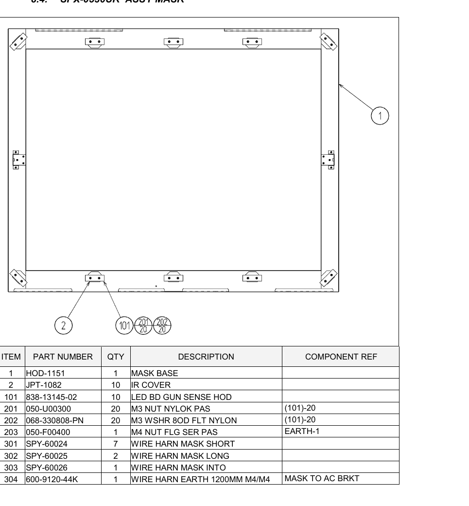
The UK service manual for The House of the Dead III DX (© Sega 2002) is the earliest manual found for this dive that describes the system Sega used for the next decade. It has two halves:
Table 2 — The UK service manual for The House of the Dead III DX (© Sega 2002) is the earliest manual found for this dive that describes the system Sega used for the next decade. It has two halves
| Where | Part | Number | Quantity |
|---|---|---|---|
| Mask round the screen | Mask base | HOD-1151 | 1 |
| IR cover | JPT-1082 | 10 | |
| LED BD GUN SENSE HOD | 838-13145-02 | 10 | |
| Wire harness mask short / long / into | SPY-60024 / -60025 / -60026 | 7 / 2 / 1 | |
| In the gun | Sensor unit | JPT-2030 | 1 per gun |
| — sensor holder | JPT-2031 | ||
| — SENSOR BD GUN SENSE | 838-13144 |
Source: §8.4 Assy Mask and §8.13 Sensor Unit.1
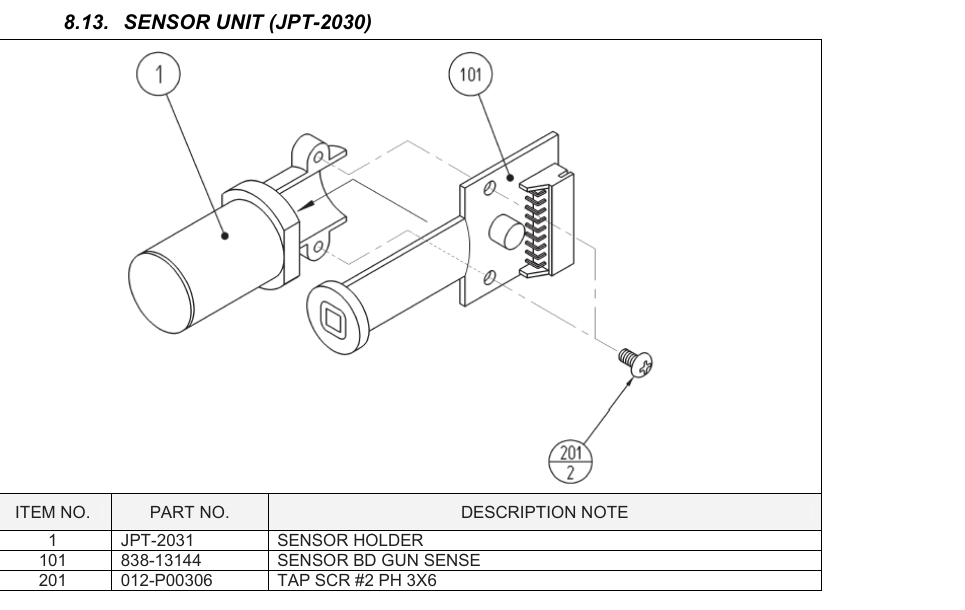
The gun itself, control unit HDT-2100, is a pump shotgun: an “ASSY SLIDE MECHA” (HDT-2120), slide grips, a front sight, a trigger on a microswitch (SS-5GL2, 509-5080) and the JPT-2030 sensor unit.1 The input test shows what the game receives from it:
“GUN-X: The X-direction (horizontal) sight position for the guns. GUN-Y: The Y-direction (vertical) sight position for the guns. SCREEN-IN: Detection of the gun sight sensors … Input is normal if the display to the right of SCREEN-IN changes from OUT to IN when the shotgun is pointed at the screen.”1
The manual calls the whole arrangement “the same or similar infrared sensing system” and “the gun sense system”.1 It does not say whether the sensor board is an image sensor or a set of photodiodes; the parts list names only a board.
4.3 Ghost Squad and The House of the Dead 4, 2004 and 2005
Sega kept the parts. The Ghost Squad deluxe manual (first printing November 2004) lists an “IR COVER” (JPT-1082) and “LED BD GUN SENSOR HOD” (838-13145-02) on its mask assembly and the same JPT-2030 sensor unit with its 838-13144 “SENSOR BD GUN SENSE” in the gun.2 Its troubleshooting table gives the failure modes of the system:2
Table 3 — Ghost Squad and The House of the Dead 4, 2004 and 2005
| Cause given | Countermeasure |
|---|---|
| ”Sights are not aligned due to changes in the surrounding environment” | Sighting adjustment in test mode |
| ”LED board malfunctioning" | "Check to ensure that the LED lights up. If it does not light up, replace" |
| "Sensor unit malfunctioning” | Replace the sensor unit |
| ”LED board and LED board cover are contaminated” | Wipe off soiled surfaces |
The LED board replacement page puts the test in one line: “In case two of LED’s do not emit light, failure and malfunctioning may be considered.”2 Each board carries two LEDs.
The House of the Dead 4 (2005) uses the same sensor unit (JPT-2030, listed with an 838-13144R sensor board) in a control unit numbered HDF-2100, and the same “LED BD GUN SENSE HOD” on the mask.3 Its output test lists “GUN MOTOR1” and “GUN MOTOR2” — the gun has a motor (Volume 5).3
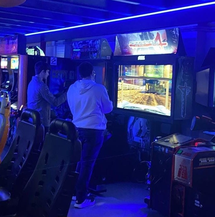
That three games across four years share one sensor-unit number and one LED-board number, and that the board’s name carries “HOD”, says that Sega designed the system once, around The House of the Dead, and reused it.
4.4 Namco Time Crisis 4, 2006
Namco’s Time Crisis 4 DX manual describes a system of the same shape with different parts. The mask around the 46-inch projection screen holds LED boards behind filters, and the gun holds a “Light Receiving Unit” (XTC4-306-754).4
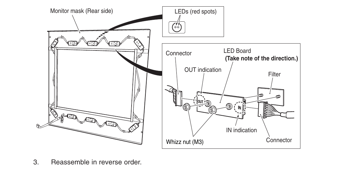
The operator is told to “Clean the following sensor section’s filters (20 locations) on the Monitor Mask everyday to maintain gun accuracy”, that “Scratches on the monitor mask can affect the Gun Assy detection performance”, and that “If the two LEDs (red spots) under the Monitor Mask’s filter … do not illuminate, the LED board may be defective” — and “any defective LED Board will prevent the proper functioning of the game”.4 The boards are static-sensitive, chained by IN and OUT connectors, and the manual’s instruction for a defective one is to replace it “as soon as possible”.4
The gun-initialise screen spells out the system’s limits. When the gun is aimed off the screen the game shows “OUT OF SCREEN”; if that message appears when the gun is on the screen, the causes are:4
- “Bright light shining or reflecting on the LEDs around the screen.”
- “Gun Assy too close to the screen. (less than 60cm)”
- “The gun is at too great an angle to the screen.”
The 60 cm minimum is the only distance limit found in any arcade manual for this dive, and it fits a sensor in the gun with a limited field of view: too close, and the LEDs on the far side of the mask fall outside it.
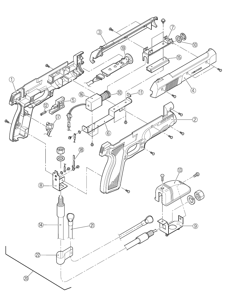
The parts list gives Gun Assy (Red) XTC4-717-333 and Gun Assy (Blue) XTC4-717-355, Solenoid Unit XTC4-717-316, Microswitch XTC4-000-666 and Light Receiving Unit XTC4-306-754.4 The recoil is in Solenoid Recoil.
A forum claim worth recording as unverified: an Arcade-Projects member wrote in 2019 that “Cobra the Arcade and Time Crisis 4 use IR guns that are cross-compatible with the Sega IR system”.7 Nothing in the Namco or Sega manuals read here confirms or refutes it; the part numbers are different.
4.5 Two Cabinets Side by Side: the Frequency Jumper
Both makers expected the same problem and solved it the same way. Sega, The House of the Dead III:1
“When games with the same or similar infrared sensing system are installed side by side, interference may occur causing malfunction or inaccuracy of the sensing system in adjacent games. A removable wire harness controls the operating frequency of the gun sense system. Removal of this harness switches from the default frequency to an alternate one. Where game machines of the same or similar type are installed side by side, remove the jumper harness (SPY-60010UK) from every other machine in the line.”
Namco, Time Crisis 4:4
“If machines using the same gun detecting system are installed side by side, cross talk may occur between them resulting in machine malfunction. If machines of the same type are to be installed side by side, make sure that they are alternately ‘Frequency Change connector’ installed Game PCB and ‘Frequency Change connector’ not installed Game PCB models.”
“Operating frequency” implies that the LEDs are modulated and the gun’s receiver is tuned to the modulation, so that a neighbour’s LEDs, at the other frequency, are rejected. Neither manual gives the frequencies. For a home builder the lesson is direct: an unmodulated IR marker bar is open to exactly this interference from a second gun system in the same room, which IR Point Tracking takes up.
4.6 Raw Thrills: a Camera in the Rifle, 2010 and 2014
The Raw Thrills cabinets built by Play Mechanix describe the gun’s sensor plainly as a camera. Terminator Salvation (© 2010) has three relevant tests:5
- IR Gun Calibration, with a dot showing “the spot where the gun is aimed”.
- Gun Camera Test. “Each gun controls a dual-track of colored dots. As you tilt each gun, the orientation of the tracks rotates as the sensors perceive the change in angle. The strength of each gun’s signal is noted in a bar chart … Note whether any of the dots disappear or flicker when near the center of the screen. This may indicate a dirty or poorly functioning camera inside the gun.”
- Gun Sensor Test. “POINT EITHER GUN AT THE SCREEN AND AIM ALL AROUND TO ACTIVATE ALL THE SENSORS. ACTIVE SENSORS ARE GREEN. INACTIVE ARE RED … If any squares remain red as the gun passes them, that particular IR sensor may be dirty or damaged.”
The first test shows the camera reporting rotation as well as position: it sees more than one point and knows their orientation. The manual calls the screen-side units “IR sensors” and warns that “Locating the cabinet near neon lights may reduce the ability of the IR sensors to accurately track the guns.”5 With a camera in the gun, the screen-side units must be what the camera sees; that they are emitters is the obvious reading, but the manual does not use the word.
Aliens Armageddon (© 2014) gives part numbers. Its deluxe rifle contains a “Camera Assembly (Complete)”, 820-00010-01, on a “Hose and Harness Assembly USB 12 Cond”, 96-1047-20, with an “LED PCB F/T4 Rifle” (500-00083-01) and a solenoid recoil (Volume 5).6 The routine maintenance, done “every time you empty the cash box”, starts “Check the camera lens. Observe the tinted lens to ensure it has no cracks, scratches or dirt”, and ends “Check IR sensors (Deluxe model only). The IR sensors are directly below and above the printed marquee on the monitor assembly.”6 The instruction “Recalibrate the guns any time the game is moved or the guns are repaired, replaced or swapped” closes the list.6
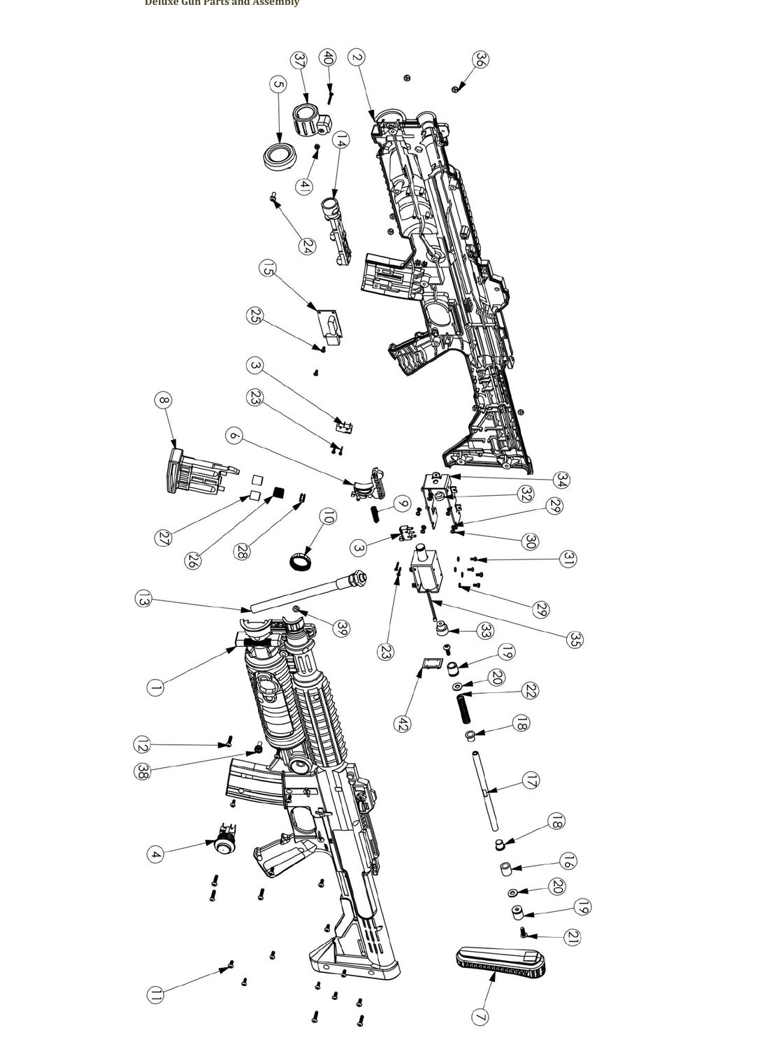
A USB camera in the gun and infrared units at the screen is the architecture of the home guns this category is building: a PixArt-type tracking camera and an LED bar (Reference Electronics, Open-Source Firmware). The Raw Thrills manuals do not name the camera’s maker.
4.7 Optical, Positional and Infrared Compared
Table 4 — Optical, Positional and Infrared Compared
| Optical (Volume 2) | Positional (Volume 3) | Infrared (this volume) | |
|---|---|---|---|
| Needs from the display | A CRT’s scanning beam, bright | Nothing | Nothing (the mask carries the emitters) |
| Gun | Handheld or mounted | Mounted only | Handheld or mounted |
| Daily cleaning | Gun lens | None | Gun lens and screen-side filters |
| Upset by | Room light, reflections, dim tube, purity | Worn pots and gears, lost calibration | Bright light on the LEDs, a neighbour on the same frequency, too close or too steep |
| Calibration | Per gun, often | Three points, stored | Per gun, after any move |
| Works on an LCD today | No (Volume 6) | Yes | Yes |
4.8 What could not be verified
- The LED wavelength and modulation frequency of the Sega and Namco systems; neither manual gives them.
- What the Sega 838-13144 and Namco XTC4-306-754 sensors are (image sensor or photodiodes).
- Cross-compatibility of Time Crisis 4 guns with Sega’s system (one forum post).
- Whether Raw Thrills’ screen-side “IR sensors” are emitters; inferred from the camera in the gun.
- Ghost Squad and House of the Dead 4 mask board counts; only House of the Dead III’s (ten) and Time Crisis 4’s (twenty filters) were read.
Sources
Footnotes
-
Sega Amusements Europe, The House of the Dead III DX Service Manual, 420-6742-01UK, © Sega 2002, game board frequency jumper, input test, §8.4, §8.12, §8.13. Internet Archive item
manualzz-id-978359. Read 2026-10-19. ↩ ↩2 ↩3 ↩4 ↩5 ↩6 -
Sega Amusements USA, Ghost Squad Deluxe Owner’s Manual, Manual No. 4201-6831-01, first printing November 2004, troubleshooting, Replacing the LED BD, Assy Mask, Sensor Unit. Internet Archive item
sega-ghost-squad; Library copy. Read 2026-10-19. ↩ ↩2 ↩3 ↩4 -
Sega, The House of the Dead 4 Owner’s Manual (2005), output test, Control Unit (HDF-2100), Sensor Unit (JPT-2030). Internet Archive item
ArcadeGameManualHod4-manual. Read 2026-10-19. ↩ ↩2 ↩3 -
Namco Bandai Games, Time Crisis 4 DX Operators Manual, Issue 2, Part No. 90500167: specifications, Preventing Cross Talk, Gun Initialize, §7-1-1, §7-1-2, §7-4, §10-14. Internet Archive item
time_crisis_4_dx_manual_issue2_ptm; Library copy. Read 2026-10-19. ↩ ↩2 ↩3 ↩4 ↩5 ↩6 ↩7 -
Play Mechanix / Raw Thrills, Terminator Salvation 42” Deluxe Setup and Operations Manual, revision 7.30.12, © 2010, installation cautions and system tests. Internet Archive item
manualzilla-id-6035891. Read 2026-10-19. ↩ ↩2 ↩3 -
Play Mechanix / Raw Thrills, Aliens Armageddon Setup and Operation Service Manual, © 2014, maintenance procedure, Deluxe Gun Parts List (pp. 55–56). Internet Archive item
manualzilla-id-6032150. Read 2026-10-19. ↩ ↩2 ↩3 ↩4 -
“Setup Time Crisis 3”, Arcade-Projects forum, post by twistedsymphony, 11 October 2019, https://www.arcade-projects.com/threads/setup-time-crisis-3.10742/, read 2026-10-19. ↩
Comments (0)