Arcade Light Guns · Volume 2
Optical Guns — The CRT Cabinets, 1983 to 2003
A lens, a photodiode board and a cable: what the manuals show inside the optical guns of Exidy, Taito, Konami, Namco, Sega, Atari Games and Midway, the board in the cabinet that times them, the screen flash, and the lighting every one of them hated
Every gun in this volume does the same job in the same way. It carries a lens and a light sensor at the muzzle, it sends the sensor’s output down its cable, and something in the cabinet decides where on the screen the gun was pointing from when the sensor saw light. That something needs the picture to be drawn by a scanning electron beam, at the moment the video timing says it is drawn, which is why every cabinet here was built around a cathode-ray tube or a CRT projector, and why none of them works on a flat panel without conversion (Volume 6).
The theory of the timing is CRT Timing’s, and the narrative of these games is History of Light Guns’s. This volume is the hardware: what each maker’s manual shows in the gun and in the cabinet.
2.1 What an Optical Arcade Gun Contains
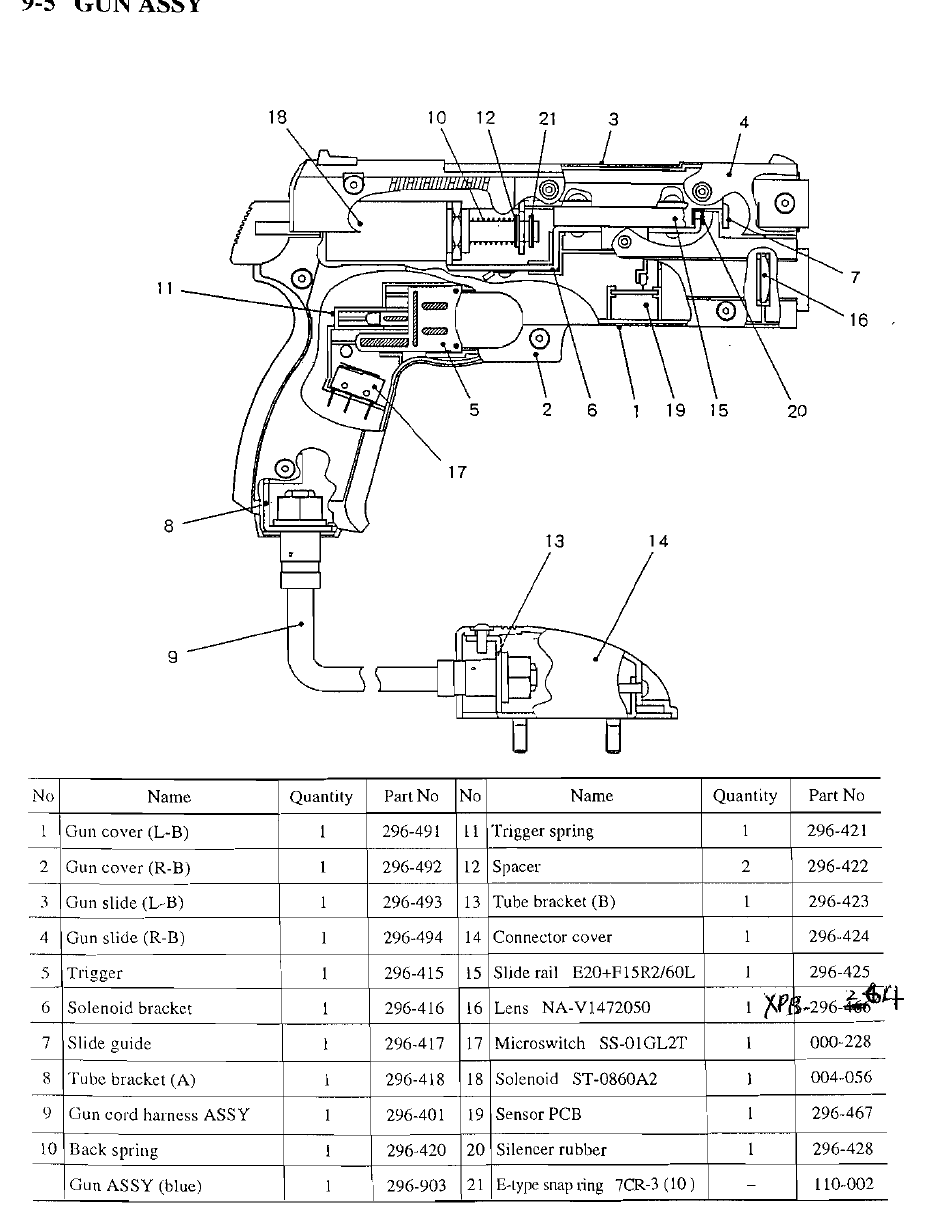
The Time Crisis SD drawing is the clearest single picture of an optical arcade gun, and its parts list is a template for the rest:
Table 1 — The Time Crisis SD drawing is the clearest single picture of an optical arcade gun, and its parts list is a template for the rest
| Item | Time Crisis SD part | Function |
|---|---|---|
| 16 | Lens NA-V1472050 | Forms an image of a small patch of screen on the sensor; restricts its field of view |
| 19 | Sensor PCB 296-467 | The photodetector and its first amplifier |
| 17 | Microswitch SS-01GL2T, 000-228 | Trigger |
| 9 | Gun cord harness ASSY 296-401 | Power, sensor and trigger lines to the cabinet |
| 18 | Solenoid ST-0860A2, 004-056 | Blowback (Volume 5) |
| — | Gun ASSY (blue) 296-903 | The whole gun |
Source: Namco, Time Crisis SD Operation Manual, §9-5.1
The lens matters more than its price suggests. Namco’s reassembly instruction is explicit: “make sure that the lens is facing the right direction. (The spherical surface of the lens should face the muzzle”.1 A lens turned round still passes light, so a gun reassembled wrong will appear to work and aim badly. The troubleshooting entry for “The gun aim is strange” has one cause, “The lens is dirty”.1
What the manuals never show is the sensor board’s circuit. None of the optical-gun manuals read for this dive includes it. The Operation Wolf diagram shows the board’s supply (±12 V) and a single output;2 the Point Blank schematic shows a three-wire “SENSOR PCB ASSY”;3 that is as far as the makers went.
2.2 Exidy: the Beam-Detect Latch, 1983 and 1986
Exidy’s 440 hardware, used for Crossbow (1983) and Chiller (1986) among others, put the timing on the game board. MAME’s documentation of the board’s registers lists “Current vertical beam position” and “Latched horizontal collision/beam detect location”, and an interrupt whose source can be selected between “collision” and “beam detect”.4 That is the console Light Phaser’s method in an arcade board: the gun’s sensor edge stops a counter, and the game reads where the beam was.
The Crossbow preliminary manual’s test menu includes “OPTICAL ADJUSTMENT” and “RESET TO FACTORY SETTINGS OF VANITY MODE AND GUN SIGHT”.5 Chiller’s gun, in the photograph that opens this dive, is mounted on a post; the beam-detect hardware makes it an optical gun all the same.
2.3 Taito Operation Wolf, 1987
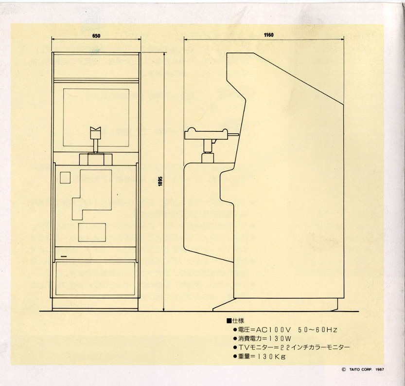
Operation Wolf is the cabinet Volume 1 corrected: its Uzi is mounted, and it is optical. Taito’s Japanese flyer gives a 22-inch colour monitor and 130 W at 100 V;6 Taito America’s manual gives 120 V, “approximately 250 watts”, 36 × 25 × 72 inches and 225 lb, and warns “the picture tube is fragile”.2 The US flyer sells “Authentic Gun Action: Your accurately detailed automatic weapon actually recoils when fired”, with “a button that launches mortar rockets” on the front of the weapon.7
The gun assembly has three parts that matter:
- The sensor board. “SENSOR P.C. BOARD ASSY”, powered from ±12 V, one output on a shielded lead.2 MAME’s notes describe it as “mostly caps/resistors and three small opto-related 8-pin ICs”.8 The collector database KLOV reports that the “photo-light sensor PCB is prone to failure”.9
- The pivot. The gun rides on a main shaft in Oiles self-lubricating bushes in a two-part gun base, held from below by a self-locking M12 nut, spring washer, plain washer and “Cam B”; the manual warns that if the press-fitted bush comes out, “Gun assembly will not be firmly fixed”.2 KLOV adds that “four springs holding the gun up often break under heavy use”.9
- The motor. A geared DC motor in a “MECHA ASSY” drives the recoil, Volume 5.
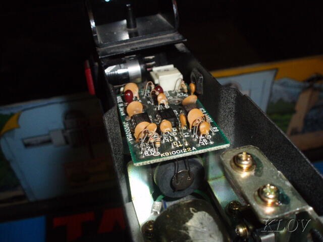
Inside the cabinet, the timing is done by the game board. MAME identifies a register bit “used to signal light gun position can be latched to inputs on v-blank”, and notes that the World and US versions carry different gun offsets, “presumably slightly different gun hardware”.8 The aux power supply schematic in the manual (a KBPC602 bridge, four 1N4004s and a 7912 regulator) supplies the ±12 V the sensor and motor need.2
2.4 Konami Lethal Enforcers, 1992
Lethal Enforcers used handheld revolver-shaped guns on cables; MAME’s notes call the board’s gun connectors “CN7/CN8 - 4 pin connectors for standard light guns”.10 The UK operators’ manual is worth reading for its troubleshooting table, which is the clearest statement of an optical gun’s failure modes found for this dive:11
Table 2 — Konami Lethal Enforcers, 1992
| Symptom | Cause given by the manual |
|---|---|
| ”ERRATIC GUN SHOT PLACEMENT" | "reflected light from fluorescent or neon lights bouncing off the screen. Strong sunlight also affects the shot placement." |
| "YOU CANNOT SHOOT CERTAIN AREA/S ON THE SCREEN” | Monitor purity: degauss the tube; check for “magnetic equipment around the cabinet" |
| "SCREEN FLASHES WHEN TRIGGER IS PULLED BUT NO SHOT IS MADE" | "Check to see the gun lens inside the barrel is clean. Adjust the monitor brightness” |
The second row is the surprising one. Purity errors change the colour of an area of the screen; that they can make an area unshootable shows the gun is sensitive to the phosphor’s brightness in that area, which a magnetised mask reduces. The third row records the screen flash: the game whitens the screen when the trigger is pulled so the sensor has a bright raster to see, and a dirty lens or a dim tube loses it. Reloading is done by pointing “your gun off screen” and pulling the trigger,11 the trick History of Light Guns explains.
The UK edition lists the guns by distributor numbers, “GUN + LEAD (RED)” 21236 and “(BLUE)” 21237, and notes the cabinet can be converted to “a standard Jamma cabinet” with conversion kit 33059 when the game is finished.11
2.5 Namco Point Blank and the Position Board, 1994
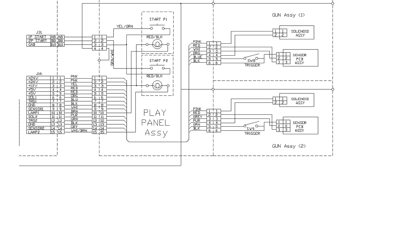
Namco separated the timing from the game. In the Point Blank schematic the PCB rack holds a “GAME PCB Assy” and a “POSITION PCB Assy”. Connector J27/J33 carries “1P SHOOT”, “2P SHOOT”, “GOUT0” to “GOUT4”, “C.SYNC” and ground between them; J32 carries +24 V, +12 V and +5 V, and for each gun SOL, TRG, SENSOR and LAMP lines.3 The position board therefore receives the video’s composite sync and each gun’s sensor output, does the timing, and hands the game the result. Each gun is six wires: two to the solenoid, three to the sensor board, one to the trigger.3
The manual’s “Gun Sight Set-Up” is entered by holding the service button while switching test mode on, and the “GOUT TEST” screen has an entry “Flash – Not Used”.3 The UK distributor lists the guns as “XPB-GUNRED” and “XPB-GUNBLUE”, with a gun chain (45000209), chain clip and holster.3 The cabinet monitor is a 28-inch Hantarex Polo.3
2.6 Sega Virtua Cop and Virtua Cop 2, 1994 and 1995
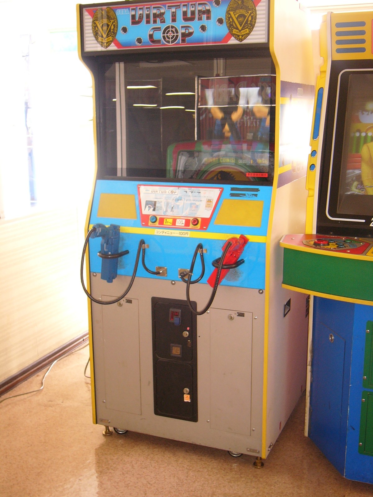
Sega’s Model 2 cabinets used one gun for both games. The Virtua Cop and Virtua Cop 2 manuals list the same “SENSOR UNIT” (COP-2020) and describe replacing the sensor board, which “fits in between LENS HOLDER L and LENS HOLDER R”.1213 Covers, trigger and stopper pin are separate parts (253-5404 left cover, 253-5405 right cover, 253-5406 trigger, with -01 and -02 suffixes for the two colours).12
In the cabinet, the first Virtua Cop’s I/O board assembly (837-11130) is a common I/O board plus an “I/O OPTION BD COP” (837-11131).12 The UK Virtua Cop 2 parts list names the cabinet board “PEC GUN SENSOR BD VCOP2” (837-12079) and a harness “LOOM RGB ELEC BD (GUN SENSOR)” (600-6657-108), which places a video connection on the gun-sensor board.13 The manuals do not describe what that board does with the video; that it needs it is consistent with timing the gun against the picture.
Sega’s caution in the first manual is the counterpart of Konami’s table: “When the controller is pointed outside the screen, it sometimes (though rarely) functions the same as when shooting inside the screen. This is caused by some other machine’s on-screen light or fluorescent light, etc. reflected on the controller.”12 Gun sighting is set in test mode by shooting the centre of grids, with default and manual adjustments for each player.13
2.7 Namco Time Crisis to Time Crisis 3, 1995 to 2003
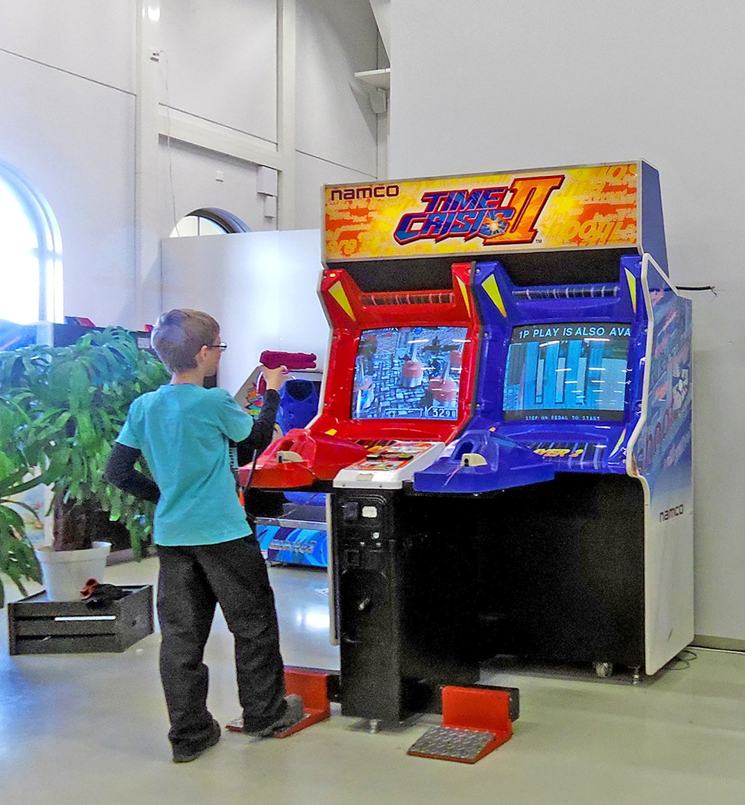
Namco’s gun stayed recognisably the same through three games. Its recoil is in Solenoid Recoil; its sensing is here.
Table 3 — Namco Time Crisis to Time Crisis 3, 1995 to 2003
| Time Crisis (SD) | Time Crisis II | Time Crisis 3 (SD) | |
|---|---|---|---|
| Gun assembly | 296-903 (blue)1 | 296-902 (red), 296-903 (blue)14 | PB03-03141-00 (pink), PB03-03141-01 (blue), with harness15 |
| Lens | NA-V1472050 | NA-V1472050, 296-466 | ”Lens” |
| Sensor | Sensor PCB 296-467 | Sensor PCB 296-467 | ”Gun Sensor PCB” |
| Solenoid | ST-0860A2, 004-056 | ST-0860A2, 004-056 | ”Solenoid” |
| Display | CRT | CRT | ”27-inch color monitor CGA x 2 units” |
The Time Crisis II manual tells the operator to “Clean the gun lens every day to keep it precise”, and warns that reflection of a fluorescent lamp “might prevent the gun sensor from functioning”.14 Time Crisis 3, on two 27-inch CGA monitors, keeps the same instructions (“Clean the gun lenses everyday”), adds a troubleshooting cause “Surrounding is too bright. — Block the external light”, and warns not to install the machine where bright light “shine[s] directly onto the monitors, since they disallow the sensors from detecting the gun positions”.15 It also carries the most unexpected warning in any manual read for this dive: “Do not remove the lenses from the Gun Assys when discarding the machine. Detached lenses can converge sunlight, causing a fire, blindness or burns.”15
Collectors on the Arcade-Projects forum agree on what the parts list implies. “TC3 won’t work with LCD anyway. It was either a crt or rear projection,” one wrote in 2017; another, “the TC3 guns will not function without an RGB CRT based display.”16 A 2019 owner describes the System 246 I/O’s gun connection as “a 6pin connection for the gun (sync/grnd/5v/trigger/ and 24v and i think 24v grnd)” — sync to the gun, which is the Point Blank arrangement moved into the gun cable.17 (One poster in the same thread claims Time Crisis 3 used a camera in the cabinet and an emitter in the gun; the manual’s own parts list, with a lens and a gun sensor PCB in the gun, contradicts that.)
2.8 Atari Games and Midway: Area 51, Maximum Force, CarnEvil
Atari Games’ Area 51 (software dated October 31, 1995) and Maximum Force (1997) share a gun board, A051987-01.1819 Area 51’s guns are “Blue Optic Gun Assembly” A054890-01 and “Red Optic Gun Assembly” A054890-02.18 Maximum Force describes itself in its specifications as “Optical Gun Type”, lists a lens (178386-001) and a light shield (03-9659), and puts the lesson of every optical cabinet in one sentence: “No amount of calibration and testing can fix a dirty optical system, loose components, defective cables, etc.” Its note on lighting is the same as everyone else’s: “Bright overhead lights can occasionally interfere with proper optical gun operation.”19 Calibration on Area 51 is done by aiming at a cross hair and holding the trigger “until the screen stops flashing”.18
Midway’s CarnEvil (1998), “with Optical Shotguns”, makes the screen flash an operator setting:20
“Flash Brightness affects gun operation … If you set flash brightness too low, the guns may not operate. If set too high, flash brightness might irritate players or reduce monitor life. This adjustment’s range is .01 to .99. For new CRTs, the recommended setting is .50.”
“For new CRTs” is the point. An ageing tube is dimmer, so the flash an optical gun relies on has to be turned up as the monitor wears, at the cost of the tube’s life.
2.9 What Every Optical Cabinet Has in Common
Read across the manuals, the optical cabinets share five things:
Table 4 — Read across the manuals, the optical cabinets share five things
| Shared feature | Evidence |
|---|---|
| A lens and a sensor board at the muzzle | Every gun parts list in this volume |
| A board in the cabinet that times the sensor against the video | Point Blank’s position PCB; Virtua Cop’s gun-sensor board on an RGB loom; Operation Wolf’s latch; Exidy’s beam-detect register |
| Daily lens cleaning | Time Crisis II and 3, Time Crisis SD, Area 51, Maximum Force, CarnEvil |
| Sensitivity to room light and reflections | Lethal Enforcers, Virtua Cop, Time Crisis II and 3, Maximum Force, CarnEvil |
| A CRT, kept bright | 22 in (Operation Wolf), 25 in Polo (Lethal Enforcers), 28 in Polo (Point Blank), 27 in CGA (Time Crisis 3); CarnEvil’s flash setting |
The last row is the one that ends these cabinets’ working lives. Volume 6 takes it up.
2.10 What could not be verified
- The circuits of any optical gun’s sensor board or of Namco’s position PCB. No manual read for this dive includes them.
- The Time Crisis SD lens part number. The printed number is overwritten by hand in the scan; the Time Crisis II list gives 296-466.
- What Sega’s gun-sensor board does with the RGB loom. Inferred from the harness name only.
- Lethal Enforcers’ maker part numbers. Only the UK distributor’s numbers were found.
- Operation Wolf’s sensor-board ICs. Described only by MAME’s notes and KLOV; no Taito schematic of the board was found.
Sources
Footnotes
-
Namco, Time Crisis SD Operation Manual, §7-2-5, §7-3-4, §9-5 (manual p. 69). Internet Archive item
arcademanual_Time_Crisis_SD_Manual; Library copy. Read 2026-10-19. ↩ ↩2 ↩3 ↩4 -
Taito America Corporation, Operation Wolf Operating Manual: power and installation, gun assembly replacement, Gun Assy Wiring Diagram, Aux Power Supply Schematic. Internet Archive item
operation_wolf_operating_manual_ptm. Read 2026-10-19. ↩ ↩2 ↩3 ↩4 ↩5 -
Namco / Brent Leisure, Point Blank Operators Manual, Part No. 90500078, © 1994, §1, §3-4, §4, §5. Internet Archive item
pointblank; Library copy. Read 2026-10-19. ↩ ↩2 ↩3 ↩4 ↩5 ↩6 -
MAME,
src/mame/exidy/exidy440.cpp, memory map notes, mamedev/mame master, read 2026-10-19. ↩ -
Exidy, Crossbow Preliminary Manual, © 1983. Internet Archive item
arcademanual_Crossbow_preliminary. Read 2026-10-19. ↩ -
Taito Corporation, Operation Wolf sales flyer (Japan), 1987, back. The Arcade Flyer Archive, https://flyers.arcade-museum.com/videogames/show/3040, read 2026-10-19. ↩
-
Taito America Corporation, Operation Wolf sales flyer (USA), 1987, front. The Arcade Flyer Archive, https://flyers.arcade-museum.com/videogames/show/712, read 2026-10-19. ↩
-
MAME,
src/mame/taito/opwolf.cpp, mamedev/mame master, read 2026-10-19. ↩ ↩2 -
KLOV / International Arcade Museum, “Operation Wolf”, https://www.arcade-museum.com/Videogame/operation-wolf, read 2026-10-19. A collector database, not a maker’s source. ↩ ↩2
-
MAME,
src/mame/konami/lethal.cpp, PCB notes, mamedev/mame master, read 2026-10-19. ↩ -
Konami, Lethal Enforcers Operators and Service Manual (UK distributor edition), troubleshooting and parts list. Internet Archive item
arcademanual_lethal-enforcers-manual. Read 2026-10-19. ↩ ↩2 ↩3 -
Sega, Virtua Cop Owner’s Manual, Manual No. 4201-6149-05, © Sega 1994. Internet Archive item
virtua-cop-manual. Read 2026-10-19. ↩ ↩2 ↩3 ↩4 -
Sega, Virtua Cop 2 Owner’s Manual (UK upright), © Sega 1995, §7, gun setting, parts lists. Internet Archive item
arcademanual_Virtua_Cop_2_Owners_Manual. Read 2026-10-19. ↩ ↩2 ↩3 -
Namco, Time Crisis II Operation Manual, cleaning and installation cautions, §10-8 Gun Assy. Internet Archive item
arcademanual_Time_Crisis_2; Library copy. Read 2026-10-19. ↩ ↩2 -
Namco America, Time Crisis 3 SD Operation Manual (2003), specifications, §5-1, §7-5-1, §8-2-5, disposal cautions, §10-5. Internet Archive item
time-crisis-3-sd. Read 2026-10-19. ↩ ↩2 ↩3 -
“Time Crisis 3 Problems”, Arcade-Projects forum, posts by ekorz and twistedsymphony, 25 May 2017, https://www.arcade-projects.com/threads/time-crisis-3-problems.3447/, read 2026-10-19. ↩
-
“Setup Time Crisis 3”, Arcade-Projects forum, post by bagheera369, 31 October 2019, https://www.arcade-projects.com/threads/setup-time-crisis-3.10742/, read 2026-10-19. ↩
-
Atari Games, Area 51 Operator’s Manual, © 1995, 1996, Chapter 2 self-test, troubleshooting, Fig. 4-2. Internet Archive item
arcademanual_Area51.man. Read 2026-10-19. ↩ ↩2 ↩3 -
Atari Games, Maximum Force 25” Dedicated Manual, April 1997, specifications, gun tests, parts. Internet Archive item
arcademanual_Maximum_Force. Read 2026-10-19. ↩ ↩2 -
Midway Games, CarnEvil 2-Player Dedicated 25” Operations Manual, 16-40069-101, November 1998, gun calibration and adjustments. Internet Archive item
arcademanual_CarnEvil_2Player_Dedicated_25in_1640069101_Nov_1998. Read 2026-10-19. ↩
Comments (0)