Steyr AUG · Volume 9
Field Strip, Detail Strip and Maintenance — In the Maker's Words, Including Where the Maker Changed Its Mind
The six-group field strip, the operator's detail strip of the gas system and bolt, the armourer's detail strip, cleaning, the oiling points on which two Steyr editions disagree, and the inspection schedule
Every procedure in this volume is taken from one of Steyr’s own manuals and is cited to it. The manuals are the Steyr Arms USA owner’s manual for the AUG A3 M1 (2023), the Steyr Arms GmbH instructions for the European AUG SA (edition EU-03, 2023), and the Steyr Mannlicher AG Maintenance Manual for the military rifle, which covers operator and armourer levels. No Australian, New Zealand, Irish or US military manual for the rifle was obtained. The Australian F88 pamphlets in particular were looked for and not found, so the military view here is Steyr’s own.123
Where the manuals disagree, both versions are given and attributed. They disagree about oiling the gas system, and the disagreement is set out in §9.7 rather than smoothed over.
9.1 The Manuals, and the Line They Draw
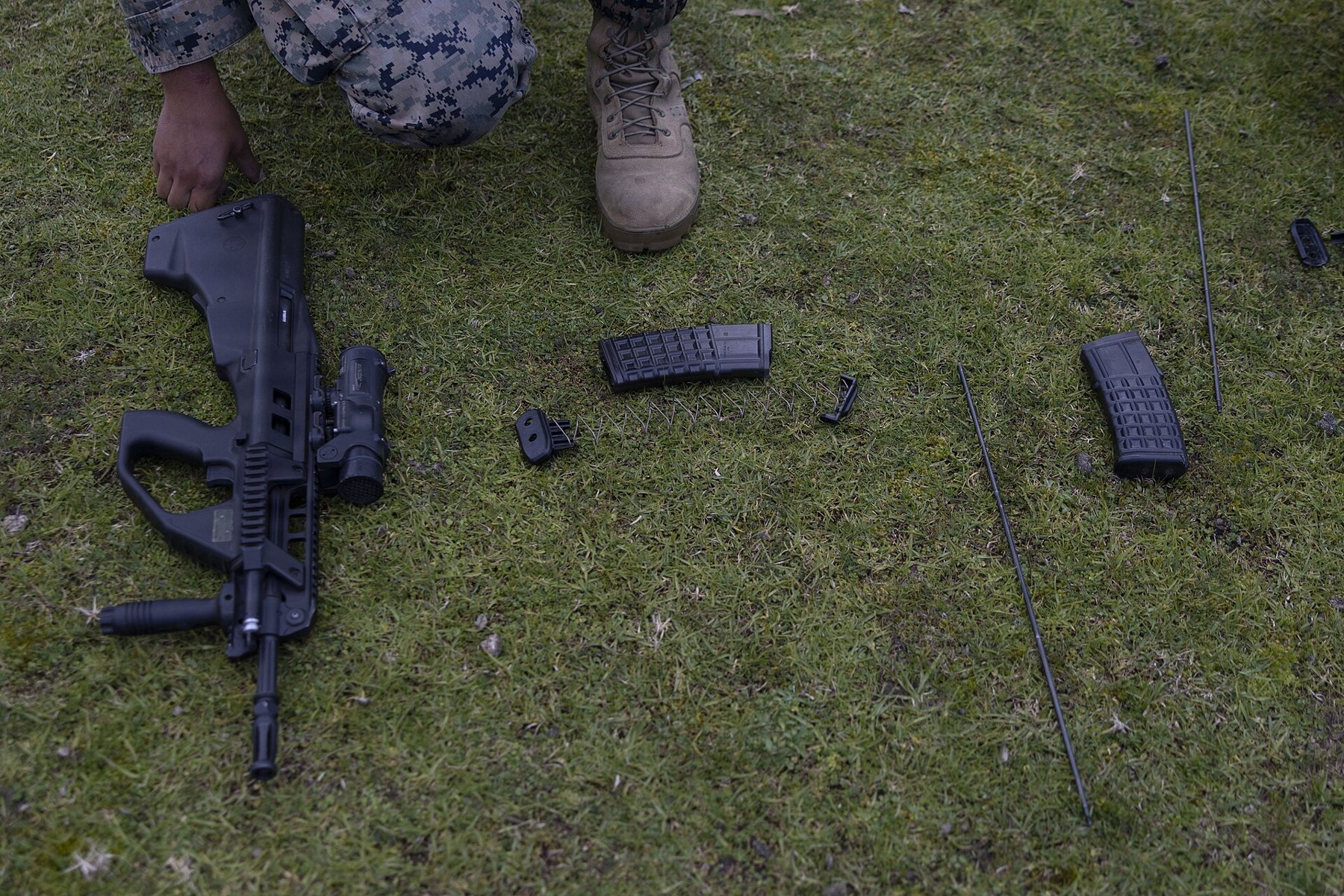
The three manuals divide the work in the same place.
- The owner or soldier field strips the rifle into its six groups, takes the gas piston and regulator out of the barrel, takes the bolt group down to bolt, firing pin, cocking piece and locking piece, empties a magazine of its spring and follower, and changes the ejection side.
- Everything further belongs to an armourer. The US manual: “Never further disassemble your STEYR AUG. Any further disassembly must be performed by STEYR authorized personnel.”4 The military manual: “The AUG can be field stripped without the use of tools. Further stripping is only to be done by trained armourers.”5 The US warranty is void if the rifle “is disassembled beyond the instructions of the Instruction Manual.”6
For a kit builder the warranty point is moot, since there is no factory warranty on a kit. The armourer procedures in §9.5 are given because a kit builder is his own armourer. They are the maker’s procedures, transcribed; they are not an invitation to take apart what does not need taking apart.
9.2 Field Strip to Six Groups
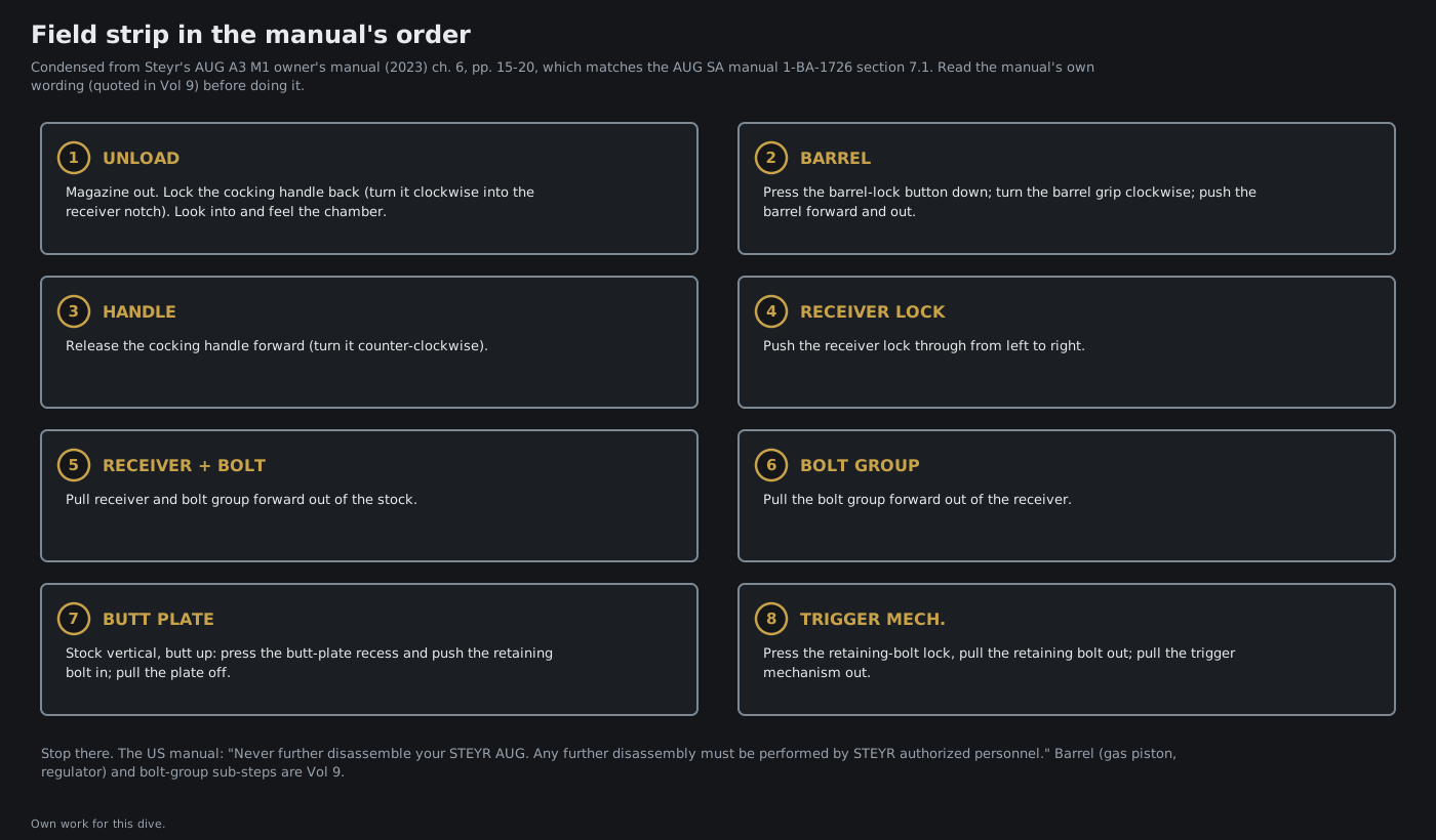
From the US A3 M1 manual, Chapter 6, which matches section 7.1 of the European manual step for step.7
Unload. Remove the magazine. Pull the cocking handle back and lock it by “turning it clockwise and allowing it to rest on the indentation on the receiver.” Check the chamber visually and by feel.
Barrel. “Hold the barrel grip with your left hand and use the thumb of your left hand to push the button of the barrel lock pin down while turning the barrel grip clockwise and pushing the barrel forward and out of the receiver.”
Cocking handle. “Move the cocking slide forward by turning it counterclockwise.”
Receiver. “Hold the top of the stock with your left hand push the receiver lock from left to right with the thumb of your right hand.” Then “Pull the receiver and bolt carrier forward and out of the stock,” and “Hold the receiver in your left hand and pull the bolt carrier forward and out of it.”
Trigger mechanism. Hold the stock vertical, butt plate up; “press the indentation on the butt plate with the thumb of your right hand, while pressing the retaining bolt on the rear of the stock in with the thumb of your left hand”; pull the butt plate off; “press the retaining bolt lock in … and pull out the retaining bolt of the stock”; “pull the trigger mechanism out of the stock.”
Two notes from the military manual belong alongside. “The barrel does not have to be removed prior to removing the housing group from stock,” and “Hammer must be cocked prior to removing trigger mechanism group.”5
One discrepancy is worth knowing before the first attempt. Every operator manual read says the barrel is turned clockwise to remove it and counter-clockwise to lock it. Steyr’s conversion instructions for fitting the push-button barrel lock to the civilian AUG Z tell the fitter to “rotate the barrel group counterclockwise” to remove it.8 The two may be describing the rotation from opposite ends; the conversion instructions’ figure was not checked. On the rifle, the barrel turns the way it turns, and it should never need force.
9.3 Operator Detail Strip: Gas System, Bolt Group, Magazine
Gas system (US manual, p. 18).7
- Hold the barrel.
- “Press the pressure piece of the gas regulator in, while turning it clockwise until its slot is in the same position as the nose of the gas cylinder.”
- “Take the gas regulator out.”
- “Use the right thrustpiece of the bolt carrier to press the gas piston partially out.”
- “Pull the gas piston and gas piston spring fully out.”
The European manual’s version says to push the pressure piece out rather than in.9 The military manual adds that the left thrust piece “may be used for this purpose” — confirming that the step is a use of the carrier as a tool.5
Bolt group (US manual, pp. 18–19).7
- “Press the two wings of the anti-turn device together and turn it upwards.”
- “Turn the firing pin counterclockwise … until it pops out by its own force.”
- “Pull the firing pin out of the bolt.”
- “Press the bolt slightly back with the thumb of your left hand while pressing the control bolt down with your right index finger.”
- “Release the pressure on the bolt.”
- “Pull the bolt and locking piece with spring and sleeve forward and out of the bolt carrier.”
- “Pull the cocking piece down and out of the bolt carrier.”
The military manual’s caution belongs at step 4: “Bolt lock is under spring pressure.”5
Magazine. The US manual says it “should not be disassembled unless necessary, and does not need to be disassembled for the normal cleaning.” When it is: a punch or the cleaning-kit tool goes into a hole in the base plate to press the retainer, the base plate slides forward off the body, and the retainer, spring and follower come out. The European manual’s caution: hold the retainer, or the spring “can jump out.”710
9.4 Changing the Ejection Side
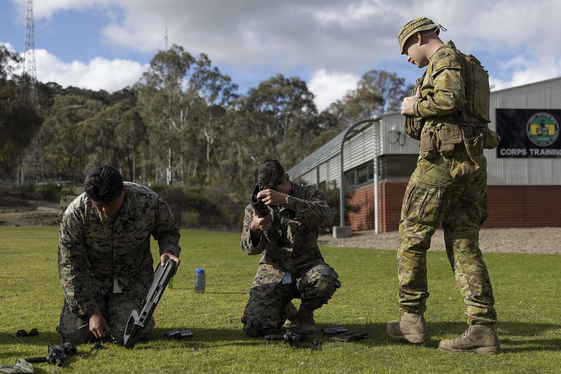
Vol 5 §5.10 describes the mechanism. The procedure, from the US manual: “The STEYR AUG come from the factory set up to eject from the right hand side. It can be modified to eject from the left hand side by replacing the bolt and modifying the stock.” Strip the bolt group and exchange the bolt. Then “lift the front of the outside ejection lid slightly with a screwdriver while pushing its back forward,” pull it off; “The inside ejection lid will drop down into the stock and can be removed through the magazine well or ejection port”; fit the inside lid “into the ejection port on the right side of the stock,” and “Slide the outside ejection lid onto the inside ejection lid on the right side of the stock until it engages.”11
9.5 Armourer Detail Strip
The Steyr Mannlicher maintenance manual’s Chapter IV covers the armourer’s work. It is given here as the manual gives it, condensed, and cited to the folio. Several passages were read from the scan’s text and are marked; the rest were checked against the page images.12
Table 1 — 9.5 Armourer Detail Strip
| Group | What the manual says | Folio |
|---|---|---|
| Barrel grip | Punch out the grip’s retaining pin; the lid is spring-loaded; a hook for refitting it “should be locally made of spring steel wire.” | 19–20 |
| Flash eliminator | Left-hand thread, with a check nut and a retaining spring ring. On refitting, run the nut to its stop, then the eliminator to its stop and back “until the central slot on the eliminator is running in line with the optical sight on top of the barrel.” | 20 |
| Gas piston rings | ”Do not remove ‘ring, piston’ except if damaged, then replace.” Rings come off with a screwdriver and go back on over the mounting cone. | 20 |
| Gas regulator | The regulator’s slide is riveted to its pin. Removal is by centre-punching and spot-drilling about 1.5 mm and driving the pin out; refitting is by riveting. | 20 |
| Barrel-lock plunger | The grub screw is secured with Loctite 242 and is warmed to remove; the old screw is discarded and the new one degreased and thread-locked. | 21 |
| Cocking handle | Punch the grip pin; lift out grip, plunger and spring; draw the body back out of the housing channel; remove the coupling and spring. | 21 |
| Optical sight | Removed on a mandrel; refitted with sealing grease on the O-rings; screws to 9.5 Nm; then purged and leak-tested under nitrogen in water at 35 ± 5 °C. (Text read from the scan.) | 22–23 |
| Carrier (“slide”) | Clamp by the guide rod; unscrew the thrust pieces “but ensure that springs are removed under control. If thrustpieces are difficult to undo then heat up the connection points of the thrustpiece and guide rod to 250° C.” Inside each rod: a short spring, a compensating rod, a long spring and a plunger. Refit with Loctite 648, thrust pieces to 20 Nm; with new springs, leave the assembled group cocked in a rifle for 12 hours. | 24 |
| Bolt | Extractor pin pushed out with a punch; ejector retaining pin driven out with a 2 mm punch (“ejector and spring under tension”); control pin held by its own retaining pin. “Prior to assembling the ‘slide, sub-assembly’, check extractor for operation.” | 24 |
| Butt | Two riveted guide rods with buffers; to replace one, spot-drill the rivet head about 2 mm deep, drive rod and buffer out forward, and re-rivet. (Read from the scan.) | 26 |
| Trigger and sear | Trigger and sear in the butt. On refitting, slide the cocked trigger mechanism in, then slide the sear back “until it rests against the ‘slide, trigger mechanism’, but does not release it,” and only then tighten the trigger screw. (Read from the scan.) | 26 |
| Receiver lock; magazine catch | Receiver lock refitted “from the right to left viewed from above the butt”; magazine catch bolt and nut with Loctite 242. | 27 |
The military trigger mechanism’s own detail strip (fo. 28–29) is not reproduced. It is select-fire, and the semi-automatic pack a kit builder uses is a different assembly that Steyr sells complete (Vol 7 §7.3).
9.6 Cleaning
When. The US manual says to clean “after you fire it or whenever it becomes exposed to sand, dust or water including humidity or condensation,” and to field strip it every time: “Cleaning without field stripping, by merely locking the bolt to the rear and inserting a cleaning rod from the muzzle, can cause dirt, oil and lubricant to build up inside the rifle.”13
The bore. The rifle carries a pull-through in the butt, and the bore is cleaned from chamber to muzzle. The military manual allows a cleaning rod “provided that it is inserted only from the chamber end.”14 The European manual’s sequence for a heavily fouled bore is a wet patch, a bristle brush (a wire brush only if “extremely dirty”), patches until clean and dry, an oiled patch, and a dry patch before shooting. It warns that after shooting “in areas with high humidity or with a silencer,” powder residue “can have a corrosive effect in connection with moisture.”15
The chamber. A dry patch after each shooting. After “a higher number of shots,” the European manual uses a power tool: “Attach a bristle brush with a diameter of approx. 11mm in a cordless screwdriver,” with solvent, then dry patches until clean.15
The gas system. Wipe cylinder, piston, spring and regulator with solvent until a patch comes out clean. “Clean the holes in the gas regulator using a piece of soft wood. Do not use a metal item to clean the holes in the gas plug head because it could damage them.”13 The military armourer’s manual goes further for heavily fouled regulator bores and lists twist drills of 1.6, 2.1, 3.2 and 8.0 mm for the purpose (read from the scan). The two instructions are for different people: the soft-wood rule is the operator’s, and the drills are an armourer’s gauge-sized tools used with the discard limits in §9.10 in view.12
Plastic parts and the trigger mechanism. A patch or rag; “If necessary, water may be used to clean the plastic parts.” Not on metal: “Do not use water to clean the metal parts … corrosion.”13
The optic. The military manual: no oil or solvent on the lenses; a soft dry cloth or plain water only.14
Suppressed .300 Blackout. Steyr Arms USA’s addendum says subsonic suppressed firing “will cause heavy fouling,” and that “After every firing session, the gas regulator, piston, and piston return spring should be removed and cleaned. The gas channel must be cleaned regularly with copper, lead, and carbon solvents.”16
9.7 Lubrication, and the Advice That Changed
The current civilian manuals list six oiling points, with the same wording in the US and European editions:1718
- “Apply 2 drops of oil onto the rings of the gas piston.”
- “Apply 2 drops of oil onto the blank area of the gas regulator.”
- “Apply 2 drops of oil onto both of the bolt guide rods.”
- “Apply 2 drops of oil between the control bolt and control slot.”
- “Apply 1 drop of oil onto the locking piece.”
- “Apply a very thin coat of oil to the metal surfaces on the outside.”
“Do not overlubricate.” The European manual explains why: “Too much gun oil collects powder.” It also adds a seventh instruction for the gas cylinder: “after each shooting: Put 2 drops of weapon oil through the hole into the gas cylinder.”15
The military maintenance manual says the opposite about the gas system, and gives its reason:
“Apply a small drop of gun oil to the regulator gas latch mechanism only. Do not oil cylinder, piston and ‘spring, piston’. The piston is hard-chrome plated and it is not necessary to oil it. Intense heat from gas will turn oil into carbon residue and interfere with normal operation. … Do not let any oil run into gas cylinder.”14
It also says “It is not necessary to oil parts of trigger mechanism group,” and of the magazine, “Do not oil.” Its oiling points for the bolt group are close to the civilian ones: two drops on each guide rod, one on the locking piece’s cam, one on the control pin.14
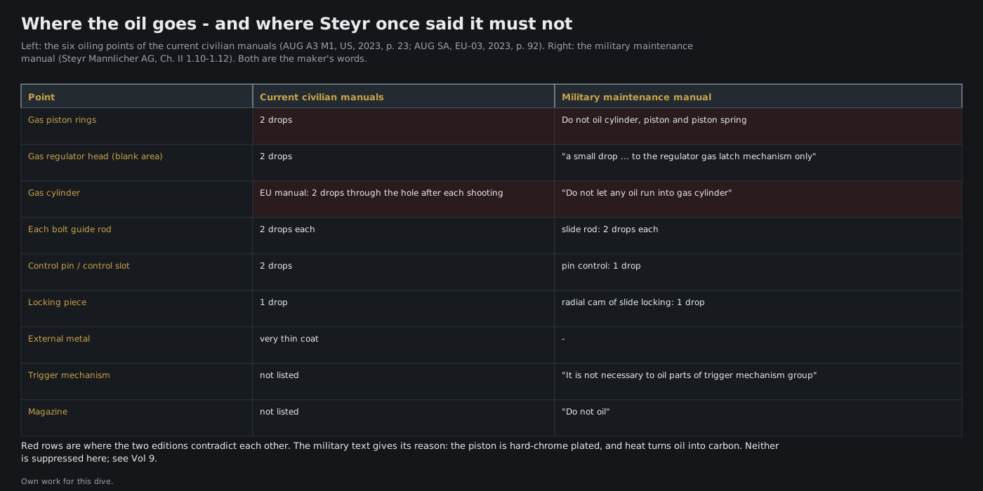
Both texts are the maker’s, and this volume does not choose between them. What can be said is what each is for. The military text was written for a select-fire rifle issued to conscripts, with a hard-chromed piston and a stated worry about carbon. The civilian texts are current, and they are the ones Steyr now ships with every rifle. A builder who follows the current manual is following the maker’s present instruction; one who keeps the gas system dry is following the maker’s earlier one, for a reason the maker gave. Either way the bolt group gets its drops, the trigger mechanism and magazine stay dry by the military text and are not on the civilian list, and nothing gets flooded.
9.8 Storage
“If the expected storage time … does not exceed 6 months, clean your weapon. If … exceeds 6 months or … higher humidity, you should also preserve your weapon.”19 The manual does not name a preservative. For the owner’s storage and transport position under Michigan law, the hub’s AR-15 5.56, Vol 7 §7.7 is the reference.
9.9 Inspection Schedule
No Steyr document read for this dive publishes a round-count schedule for replacing parts. What the manuals do give:
- Daily operator service (military manual, Chapter III): wipe the oil from bore and chamber; retract the bolt to check that it moves freely; check the magazine’s retention and the catch; check that the optic’s lenses are clear.12
- After firing: the cleaning in §9.6 and a look at the parts the stoppage tables name (§9.10).
- Every five years or 5,000 rounds: the US warranty requires the rifle to be “professionally cleaned and inspected at least once every five years or every five thousand rounds, whichever comes first by a Steyr authorized gunsmith or armorer.”6 That is a warranty condition, not a published wear interval, and a kit rifle has no factory warranty. It is still the only interval the maker publishes, and it is a reasonable schedule for the detailed inspection below.
- After a bolt or barrel is replaced: headspace gauge and a 30-shot test (Vol 7 §§7.8, 7.10).12
The armourer’s inspection table in the military manual lists what to look at:12
Table 2 — 9.9 Inspection Schedule
| Group | Inspect |
|---|---|
| Barrel and barrel extension | ”Inspect surfaces for cracks or defects. Check barrel extension for burrs, broken or worn locking lugs. Inspect bore for damage.” Gas plug bores. |
| Housing (receiver) | Optic screws at 9.5 Nm. |
| Gun lock (bolt group) | Carrier and bolt for cracks. |
| Butt | Cracks and breakages; the position of the sear to the trigger. |
| Trigger mechanism | Cracks. |
9.10 Wear Parts and Discard Limits
Steyr names its own wear parts in the US warranty, which excludes “normal wear and tear of parts that must be periodically replaced, including, but not limited to, springs, recoil assemblies, extractors, pistons, piston rings.”6 The military armourer’s manual gives measurable discard limits, and they are the most useful numbers in the maintenance literature:12
Table 3 — 9.10 Wear Parts and Discard Limits
| Part | Discard when | Folio |
|---|---|---|
| Gas regulator (gas plug head) | “As soon as the gas plug head shows a max. diameter of 2,3 mm at the largest hole and of 1,8 mm at the smallest hole.” | 20 |
| Gas piston | ”when the chromium layer on the diameter [or] on the face is peeled off” | 20 |
| Extractor | ”Fracture and wear (no longer true to gauge size according to WL-7915 and WL-7604)“ | 25 |
| Extractor spring | ”Any cracks and fractures” | 25 |
| Ejector | ”Fracture or no longer true to gauge size according to WL-6341” | 25 |
| Ejector spring | ”Any cracks and fractures; minimum length = 25 mm” | 25 |
| Locking-piece spring (“spring, slide locking”) | “When min. length is below 75 mm and in case of deformation” | 25 |
| Bolt | ”Any cracks and fractures” | 25 |
| Firing pin | ”Fracture or no longer gauge-size according to WL-6336” | 25 |
| Hammer springs | leg angle not correct, or cracked (read from the scan) | 28–29 |
| Stock | ”A Steyr AUG butt must only be replaced when cracks or breakages of the material exist which are discernible with the naked eye.” The two halves are “inseparably connected by friction welding.” | 5, 31 |
The two spring lengths and the gas-port diameters can be checked with calipers and pin gauges. The extractor, ejector and firing-pin limits need Steyr’s own gauges, which are not a retail item; without them, those parts are inspected for cracks and chips and replaced as a set when in doubt. Steyr Arms USA sells a “Spare Parts Kit” of “high wear components” — piston rings, springs, locking components, extractor and ejector assemblies and a firing pin — at $249.00 (19 September 2026), and complete right- or left-hand bolts at $330.00.20 Vol 10 takes the failures themselves.
9.11 What Could Not Be Confirmed
- A military field manual from Australia, New Zealand, Ireland or the US. None was found; the military view here is Steyr’s own maintenance manual.
- The date and edition of the Steyr Mannlicher maintenance manual. It is undated; it lists 417, 508 and 621 mm barrels and calls the grenade gas setting “old versions.”
- Steyr’s headspace-gauging procedure, the tool list’s exact wording, the butt guide-rod riveting, the trigger-and-sear adjustment and the regulator-cleaning drills, which were read from the scan’s text rather than checked on the page images.
- The barrel’s direction of rotation in Steyr’s AUG Z conversion instructions, which contradicts the operator manuals as printed.
- Any round-count wear interval. None is published in the documents read.
Sources
Footnotes
-
Steyr Mannlicher Aktiengesellschaft, Maintenance Manual, Army Universal Assault Rifle, Steyr AUG, Cal. .223 (5,56 mm), undated. Internet Archive, https://archive.org/details/maintenance-manual-army-universal-assault-rifle-steyr-aug, retrieved 2026-09-19. ↩
-
Steyr Arms, Inc., Owner’s Manual STEYR AUG A3 M1, 2023, https://steyr-arms.us/wp-content/uploads/2023/07/AUG_A3_M1_US_2023.pdf, retrieved 2026-09-19. Page numbers are the PDF’s. ↩
-
Steyr Arms GmbH, Instructions for use STEYR AUG SA, 1-BA-1726, EU-03, 2023, https://www.steyr-arms.com/wp-content/uploads/2023/03/BA-STEYR-AUG-SA_ende_1-BA-1726_EU-03.pdf, retrieved 2026-09-19. ↩
-
AUG A3 M1 manual (2023), p. 20. ↩
-
Maintenance Manual, Chapter II §1.8, field stripping, and §1.11 (gun lock group). The caution “Bolt lock is under spring pressure” and the note on the left thrust piece are from this section. ↩ ↩2 ↩3 ↩4
-
AUG A3 M1 manual (2023), Chapter 10, pp. 30–31 (warranty, exclusions, and the five-year or 5,000-round inspection condition). ↩ ↩2 ↩3
-
Steyr Arms GmbH, Umbauanleitung Laufwechsel (conversion instructions, toolless barrel change) for the STEYR AUG Z, 1-MM-1204, EU-01, 2021, pp. 3–8, https://www.steyr-arms.com/wp-content/uploads/2023/02/STEYR-AUG-Z_Umbauanleitung-Laufwechsel_EU-01_de_en_1-MM-1204.pdf, retrieved 2026-09-19. ↩
-
AUG SA manual (EU-03), §7.2, pp. 65–66. ↩
-
AUG SA manual (EU-03), §7.4, p. 69. ↩
-
AUG A3 M1 manual (2023), p. 20. ↩
-
Maintenance Manual, Chapter III (preventive maintenance) and Chapter IV §§2–4 (repair operations, elimination criteria, inspection, replacement of parts), fo. 19–32. Passages marked “read from the scan” were taken from the Internet Archive text layer; the others were checked against the page images. ↩ ↩2 ↩3 ↩4 ↩5 ↩6
-
Maintenance Manual, Chapter II §§1.9–1.14 (cleaning and lubrication). Read from the Internet Archive text layer. ↩ ↩2 ↩3 ↩4
-
Steyr Arms, Inc., AUG A3 M1 .300 Blackout addendum, 2024, p. 3, https://steyr-arms.us/wp-content/uploads/2024/03/AUG-A3M1-300-Blackout.pdf, retrieved 2026-09-19. ↩
-
AUG A3 M1 manual (2023), p. 23. ↩
-
AUG SA manual (EU-03), §8.5, p. 92. ↩
-
AUG SA manual (EU-03), p. 85. ↩
-
Steyr Arms, Inc., online store, https://steyr-arms.us/shop/category/tactical/aug/, product data read 2026-09-19 (AUG Kits — Spare Parts Kit, SKU 1200000600, $249.00; AUG Bolts, SKU 120004057, $330.00). ↩
Comments (0)