Remington Nylon 66 · Volume 3
How It Works — A Receiver Made of Nylon
The moulded shell, the barrel mount, the cover and its five jobs, the bolt and the sliding striker in nylon tracks, Homer Young's sear block, feeding from the butt, and how the lever, bolt and box-magazine relatives differ
3.1 The Principle
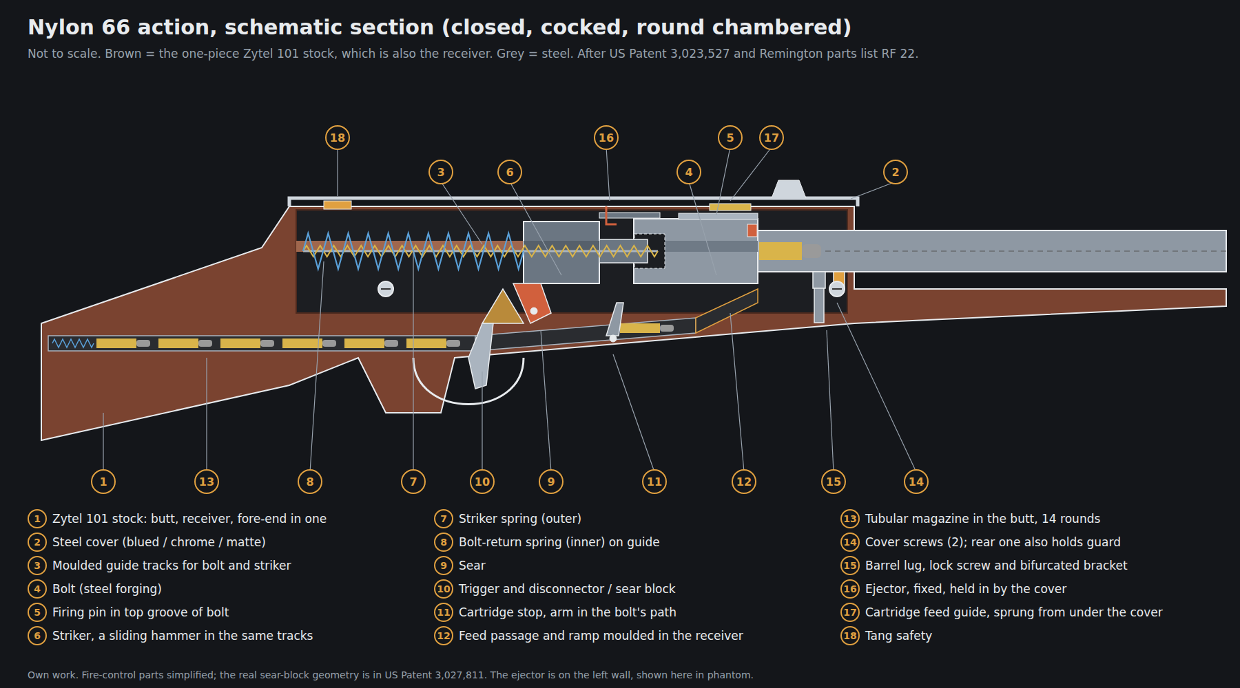
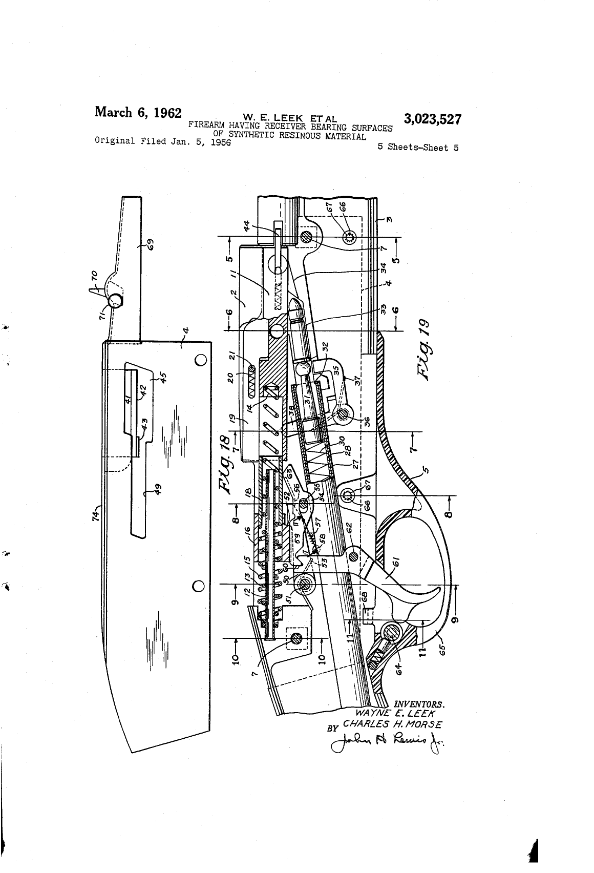
The Nylon 66 is a straight-blowback, striker-fired .22 autoloader. None of that is unusual. What is unusual is where the parts run. On a conventional .22 the bolt slides in a steel receiver, and the receiver is screwed into a wooden stock. On the Nylon 66 there is no steel receiver. The stock is moulded in two halves of DuPont’s Zytel 101 nylon, and the middle of that moulding is the receiver: it has guide tracks for the bolt, a cradle for the barrel, pockets for the fire-control parts, and a moulded feed passage for the cartridges. The patent that covers it is titled for exactly this: “Firearm Having Receiver Bearing Surfaces of Synthetic Resinous Material”.1
Everything else follows from that choice. The steel parts are small, stamped or cast, and dropped into moulded pockets. The springs and pins are held in by the shell. A single sheet-steel cover closes the top and holds several parts in. This volume works through the rifle in that order: the shell, the barrel, the cover, the moving parts, the fire control, the feed, the ejection, and finally how the other Nylon models differ. Part names are Remington’s, from the factory parts list, with its view numbers where useful.2
3.2 The Shell
The Leek–Morse patent describes a “full length stock assembly” moulded “of a suitable thermoplastic or thermosetting resinous material, with recesses provided in the molded stock assembly to accommodate the barrel and to guide and support all of the necessary functional parts normally guided and supported by or secured to a conventional receiver.”1 It is made in two halves, left and right. Marcot’s history, following Remington’s records, gives the production method: “a Zytel-101 stock that was injection-molded in two halves, of which one-half had a tongue and the other a groove. They were then bonded together.”3
The patent offers two ways of making that joint. It could be cemented “by the application of a suitable cement or solvent either to the tongue or to the groove, or both”, or “autogenously welded”. The welding method it describes is induction welding: “placing a small, preferably ferromagnetic, wire throughout the extremity of the groove, then assembling the tongued section thereto and subjecting the entire assembly to the influence of an induction heating unit which causes … localized melting … [and] produces an extremely effective welded joint without flash.”1 Which method Ilion used in production is not stated by any source located; Marcot and Simmons both say only “bonded”. The distinction matters to a repairer, and it comes up again in Volume 5.
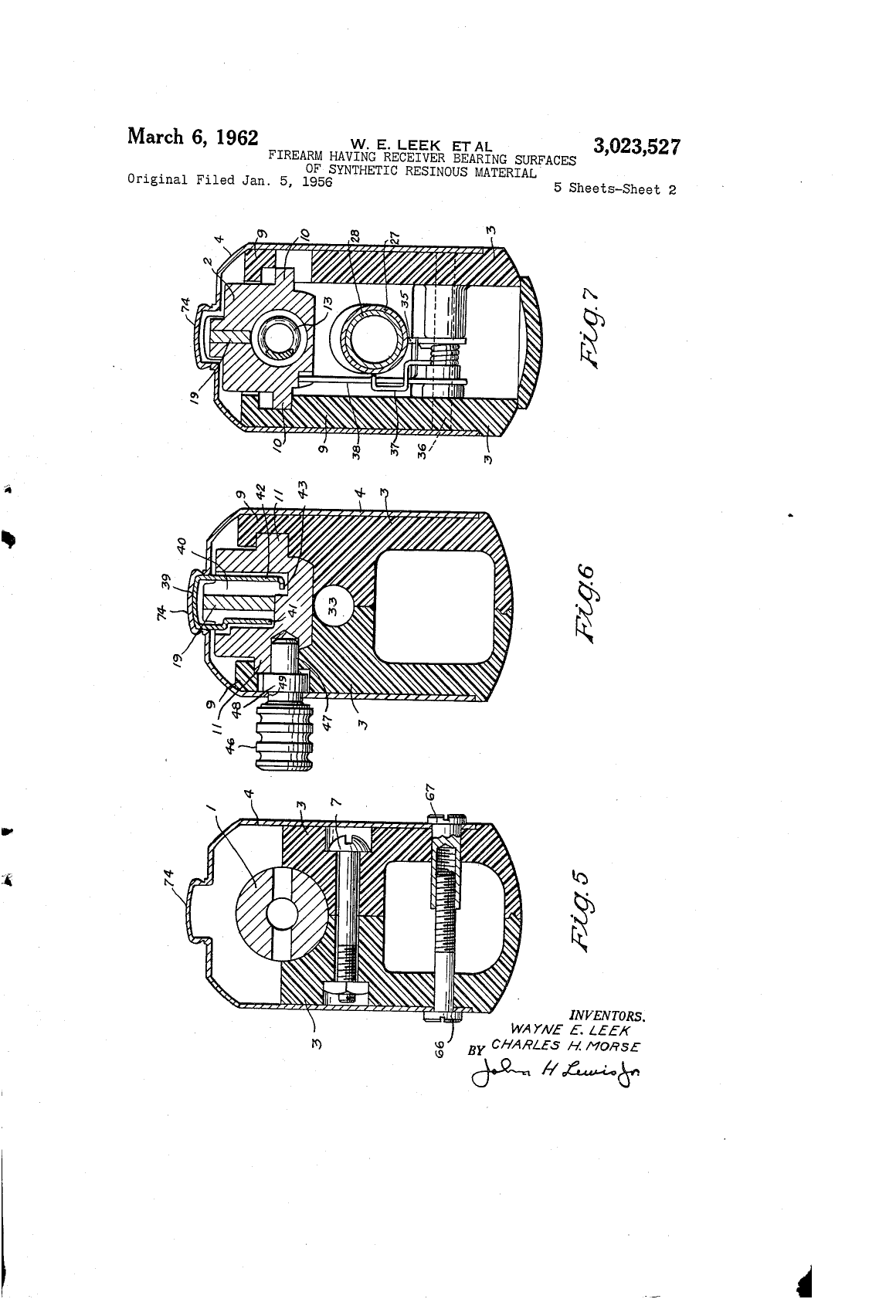
The halves are clamped as well as bonded. “At appropriate points, the joining of the halves of the stock assembly may be reinforced by cross-bolts 7 which may be covered by appropriate inlays 8.”1 In the production rifle, Marcot and Simmons count “two reinforcing screws with nuts under the receiver cover, and … one more under the ivory white diamonds on each side of the fore-end”.3 The white diamonds, the rifle’s best-known decoration, are the caps on a structural fastener. Volume 6 makes the case that most of the rifle’s look comes from its construction in the same way.
3.3 How the Barrel Is Held
The barrel is not threaded into anything. It lies in a semicircular cradle moulded into the front of the receiver section and is pulled down into it by a screw. The patent describes “a barrel lug 22 … secured … to the lower face of the barrel” and “threadably engaged by a barrel hold-down screw 23 secured in a suitable hole in the receiver portion”. Recoil is taken by “a bifurcated barrel bracket” that sits on the hold-down screw and engages “opposed cuts 25 in the surface of the barrel which define recoil shoulders thereon” and a recess in the solid nylon of the receiver “which provides recoil shoulders in the stock”.1 Recoil therefore goes from the barrel’s cuts into a steel bracket and from the bracket into the nylon.
Remington’s parts list names the production parts: barrel (3), barrel bracket (4), barrel support (5) and barrel lock screw (6).2 Simmons notes that in the very earliest rifles “the barrel bracket and the later separate barrel support were one piece”, and that the Brazilian copy’s barrel support is marked “FRENTE” where Remington’s reads “FRONT”, which tells an assembler which way round it goes.4 Removing the barrel is a matter of taking off the cover, backing out the lock screw, lifting the bracket and sliding the barrel out of the stock. Remington’s own leaflet describes that sequence as the way to clear a cartridge jammed in the chamber (Volume 5).
The rest of the barrel is ordinary: “just over 19½ inches”, six grooves with right-hand twist according to Simmons, and two small gas-relief cuts at the breech “added very soon after production started”, so that “in the event of a ruptured shell casing, these cuts allow the hot gases to escape in a vertical direction, thus not hurting the shooter.”4 The front sight is fixed to the barrel by two screws.5
3.4 The Cover and Its Five Jobs
The pressed-steel cover over the receiver was there to make the rifle look conventional. Marcot and Simmons both say so: “In order to avoid shooter rejection of this plastic gun, the designers covered the nylon receiver with a blued steel stamping.” Then, as they put it, “as long as they were going to disguise the receiver with a steel shell, they would make the shell serve some useful purpose”.34 The cover has five jobs:
- It closes the action. The patent calls it a stamping “adapted to be slipped over the top part of the receiver portion of the stock assembly, to enclose within it all of the working parts and to mask the joint between the rear end of the barrel and the stock assembly.”1
- It carries the rear sight, riveted to it and adjustable for windage and elevation by coin-slotted screws that are staked so they cannot be lost.5
- It carries the scope mount. Two dovetail grooves in the top panel take “tip-off” mounts.5
- It holds the ejector in. Remington’s cleaning instructions say to “remove ejector from exposed left side of rifle” once the cover is off; the ejector is a loose fit that stays in place only because the cover holds it.5
- It springs the feed guide. “The flat spring that tensions the cartridge feed guide is mounted by a rivet to the underside of the cover.”3
After October 1967 it has a sixth job: it carries the serial number (Volume 7).
The cover is held by two screws. The patent describes “a pair of cover retaining screws 66 threadably engaging headed sleeves 67. The rearmost of the cover retaining screws 66 has the additional function of retaining the trigger guard 5”.1 That arrangement explains two well-known owner problems. Remove the rear screw and the trigger guard is loose too. Overtighten either screw and the load goes into a sleeve seated in nylon.
The cover’s disguise also creates a known accuracy problem. Because the scope sits on a thin stamping over a plastic receiver instead of on the barrel’s own receiver, Marcot and Simmons both report that “when a scope was mounted and the gun was gripped too rigidly the point of impact could change.”3 The rear sight has the same limitation, but open sights are rarely demanding enough to show it.
3.5 Bolt, Striker and Two Springs
Two steel parts ride in the nylon tracks: the bolt and, behind it, a separate striker. The patent’s description of the arrangement:
A bolt return spring 13 … is seated in a counterbore 14 in the bolt body and acts to urge the bolt body to its foremost position … A firing pin spring 15 … surrounds the bolt return spring 13, bearing at its forward end on a shoulder formed in a firing pin striker 16 … [which] is also provided with longitudinally extending guide ribs 17 which travel in the same tracks in the side walls 9 provided for the guidance of the bolt … [and] a forwardly extending tubular portion 18 which is guided in the counterbore in the back end of the bolt body.1
In other words, the two springs are concentric on a single guide: the inner one returns the bolt and the outer one drives the striker. The striker is a hammer that slides in a straight line instead of pivoting. When the sear releases it, it runs forward “into forceful engagement with a firing pin 19 which is supported in a longitudinally extending groove in the top face of the bolt body”, and a firing-pin return spring pulls the pin back off the rim afterwards.1 Remington’s parts list confirms the production parts: action spring (1) and action spring plunger (2), bolt (7), firing pin (23) with its retaining pin, retractor spring and stop pin, firing pin striker (27), striker spring (28) and striker spring sleeve (53).2
Both parts were made cheaply and well. The bolt is “a steel machined forging”. The striker was “either an investment steel casting or a forging, which required no machining except for the hole down its center”; Simmons adds that the earliest strikers “were machined all over and appear to have been made from steel bar stock” before the cast part took over.34 The bolt handle (8) is a separate part that pulls straight out of the bolt, which is the first step of every disassembly.
3.6 The Fire Control: Homer Young’s Sear Block
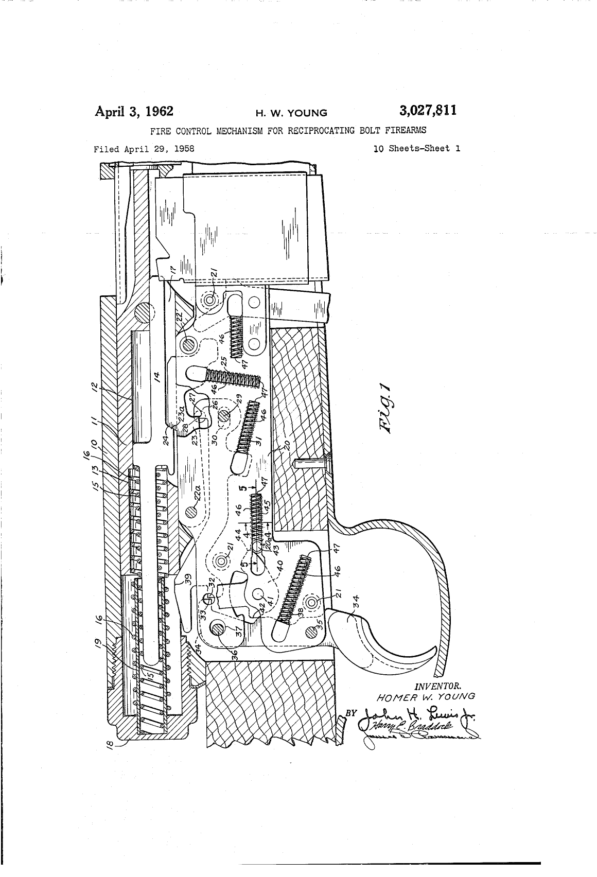
The fire-control group is Homer W. Young’s patent, US 3,027,811, “Fire Control Mechanism for Reciprocating Bolt Firearms”, filed 29 April 1958 and issued 3 April 1962.6 Its parts are sheet-metal stampings: disconnector (15) with its pivot, pivot spring and pivot pin; sear (49) with its pin and spring; trigger (54); and the safety (42) with its lever, detent ball and spring.2 Simmons, who read the patent, explains the principle more clearly than the patent does:
The action of the 66 is very interesting in that it uses a sear block mechanism. In this system the sear itself is free to pivot out of engagement with the striker against its own spring tension. This is because it is over-ridden by the much stronger cocked striker spring tension. All this above movement is prevented by the disconnector/sear block stopping any unlocking movement of the sear. When the trigger is pulled, the disconnector/sear block moves forward and unlocks the sear which releases the striker. When the bolt, after firing, blows rearward driving the striker back, the disconnector/sear block is detached from the trigger, which allows the striker to be locked in the cocked position. In addition to the normal function just described, the disconnector/sear block prevents accidental jar firing of the rifle.4
The point of the design is that the sear engagement is not what holds the striker. The striker spring is always trying to push the sear out of the way, and a separate block stops it from moving. The trigger’s job is to move that block, not to drag a loaded sear surface across a notch. That is why Simmons found the triggers “excellent” on rifles assembled “with little or no hand fitting”. The pull does not depend on a hand-stoned sear.
The safety is a sliding thumbpiece on the tang behind the cover. Remington’s instructions: pushed rearward, it is ON SAFE and “the RED dot will not show”; pushed forward it is at FIRE, and “the RED dot will show”. The same leaflet adds that the safety “is not intended to justify careless or irresponsible handling”.5 Simmons notes that the patents show the designers undecided between a cross-bolt safety behind the trigger and the tang slide, and production used the tang.4
3.7 Feeding from the Butt
The magazine is a tube inside the buttstock that loads through the buttplate. The inner tube (32) carries the magazine follower (33) and spring (37). It is locked into the moulded outer tube (38) by a magazine plug (36) that turns in the buttplate recess, working the magazine lock (34).2 To load, Remington’s instructions say to hold the rifle muzzle down, “reach into butt plate recess and turn magazine plug to unlock magazine tube. Pull magazine tube from stock. Drop long rifle cartridges into magazine tube bullet first.” It holds fourteen.5 Marcot notes the one drawback: unlike Remington’s earlier Models 16, 24 and 241, which loaded through a port in the side of the butt, the Nylon’s tube “had to be completely removed before reloading”.3
From the tube, the cartridges go forward along a passage moulded in the nylon, underneath the action. The patent: “The receiver portion B of the stock assembly is formed to define a cartridge feed passage 33 and a feed ramp 34 in substantial prolongation of the magazine tube.” One round at a time is released by a cartridge stop (35) “provided with a cartridge stop spring 37 which urges the end of the cartridge stop to extend into the cartridge feed passage … in position to intersect the head or rim of a cartridge … and prevent the delivery of more than one cartridge”. The stop is worked by the bolt: it has “an arm 38 which extends upwardly into the path of the breech bolt in position to be overridden by a cam surface in the breech bolt whenever the breech bolt is displaced rearwardly”.1
The sequence the patent describes is this. When the bolt comes back, the stop rises. The round already in the passage is free to be pushed “up the feed ramp, and into a position to be picked up by the bolt face and pushed home into the chamber”, while the one behind it is held by its rim. The held round “will not be released for further movement until such time as the bolt has substantially reached its breech closing position and the cam surface has passed forwardly of the arm 38.”1 So the magazine can never push a second round into the bolt’s path while the bolt is moving.
At the top of the ramp the round meets the cartridge feed guide (9), which rides in the bolt and is pressed down by the flat spring under the cover, lining the round up with the chamber as the bolt closes.23 The patent drawings show an earlier form, a guide fixed to the cover with flanges that straddle the round. Simmons noticed that the drawings show no separate feed guide at all, “because, obviously, it had not yet been found necessary”. He also records that the production guide was first held in the bolt by two hook-shaped arms on a roll pin, later by two holes that fully enclosed the pin.4
When the magazine is empty, the follower comes up the passage behind the last round. Remington’s instructions use it as an empty indicator: “A colored magazine follower should be seen from ejection port when action is empty.”5 Simmons describes it as “a bright yellow follower”.4
3.8 Extraction, Ejection, and an Extractor That Does Nothing
After firing, nothing holds the breech closed except the bolt’s mass and the return spring. The case pushes the bolt straight back. Simmons makes a point about this that is true of most rimfire blowbacks but is rarely stated: “When a blowback gun cycles, the shell acts as a piston, driving the bolt rearward without the extractor doing anything. The extractor is functional, of course, when an unfired cartridge is withdrawn from the gun’s breech manually. To verify this, I removed the extractor from one and the rifle functioned perfectly.”4 The extractor (20), with its plunger and spring, is there for unloading a live round by hand, and for a fired case that sticks.
Near the rear of the bolt’s travel the case head strikes the ejector (19), a fixed piece on the left of the receiver held in by the cover, and leaves through the ejection port on the right.5 The rifle fires in any attitude. Simmons: “no matter if the rifle is held right side up or upside down or any place in between it will keep firing”,4 and Conner’s 1958 field report records firing it “right-side-up, upside-down and sideways”.3
3.9 The Cycle, Step by Step
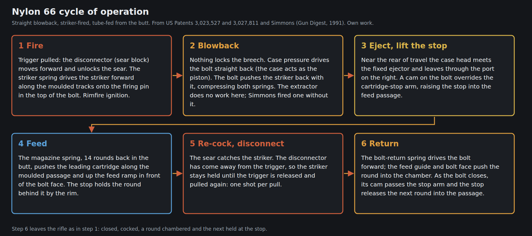
The cycle, put together from the sources above:
- Fire. The trigger moves the sear block; the sear is released; the striker spring drives the striker along the tracks onto the firing pin.
- Blowback. The case pushes the bolt back. The bolt carries the striker back with it through the striker’s tubular nose, compressing both springs.
- Eject and lift the stop. The case hits the fixed ejector and leaves to the right. The bolt’s cam overrides the stop arm and the stop rises into the feed passage.
- Feed. The magazine spring drives the leading round up the ramp in front of the bolt face; the next round is held at the stop by its rim.
- Re-cock and disconnect. The sear catches the striker. The disconnector has come away from the trigger, so there is one shot per pull; the trigger must be released to reset.
- Return. The bolt-return spring drives the bolt forward, chambering the round. As the bolt closes, the cam passes the stop arm and the next round moves up to the stop.
3.10 Why It Runs Without Oil, and When It Will Not
Remington’s claim that the functional parts need no lubricant is not advertising exaggeration. It follows from the material. The patent explains the choice: “the low friction, anti-galling characteristics of nylon, working in contact with metal particularly under adverse temperature and weather conditions, are especially desirable in regard to the tracks in the receiver section which support and guide the bolt and striker”.1 DuPont’s handbook describes nylon 6,6 as having “low coefficients of friction and excellent resistance to abrasion”.7 Steel on nylon is a bearing pair that works dry, and the Nylon 66 puts every steel-on-housing sliding contact on nylon.
Oil adds nothing to that pair and holds grit. Remington’s instructions: “The metallic action parts of the Remington NYLON 66 will perform best and remain clean longer if little or no oil is used. The nylon parts need no oil.”5 The Nylon 77 folder goes further: “For best results do not oil Nylon parts.”8
“Needs no oil” does not mean “needs no cleaning”. A .22 blowback puts unburnt powder, lubricant from the bullets and lead into the action on every shot, and the moulded tracks collect it. Simmons: “I have seen Remington Nylons that were never cleaned by their former owners and they were full of carbon deposits and grit and sand. Although the guns still worked, they are subject to unwarranted wear because of the dirt.”4 Nylon is tough, but it is softer than grit, and a grinding paste of fouling and sand wears the tracks the rifle depends on. The cleaning routine Remington prescribes, and what to keep off the nylon, are in Volume 5.
3.11 Ammunition
The rifle is chambered for .22 Long Rifle only. Remington’s leaflet is explicit that “use of 22 caliber long or 22 caliber short cartridges may cause jamming of cartridge in barrel chamber”, and gives a procedure for clearing one (Volume 5).5 The feed passage, ramp and stop are dimensioned for the Long Rifle round’s length, and a Short or Long positions its rim wrongly for the stop and the bolt face. The only exception is the separate Gallery Special, built for Shorts (below).
Marcot describes the magazine as holding “14 standard or high-velocity .22 LR rimfire cartridges”.3 In practice a straight blowback with springs chosen for high-velocity ammunition may not cycle reliably on the weakest loads. Simmons recorded that his Brazilian copy, brand new, had trouble cycling standard-velocity ammunition with a full magazine until it had fired a few strings.4 Ammunition selection belongs to the hub’s .22 Rimfire dive, whose choosing-by-gun volume covers the trade-offs; nothing about it is special to this rifle except the Long-Rifle-only chamber.
3.12 The Relatives: Gallery, Box, Lever and Bolt
The same shell and the same principle were stretched into seven more rifles. Volume 4 covers how to identify them; mechanically, they differ as follows.
Gallery Special (66GS, .22 Short). A Nylon 66 for shooting galleries. Simmons: “The ‘Gallery Special’ uses a lot of different parts in its manufacture, the bolt and the striker and their respective springs are different for functional reasons, while a counter chain retainer and a cartridge deflector (typical shooting gallery hardware) are added.” Remington’s parts list confirms its own action spring, barrel, bolt, feed guide, feed insert and spring, cartridge stop, disconnector, ejector, extractor, striker and striker spring, inner magazine tube, magazine bushing, deflector and counter chain retainer. All were marked obsolete by the time of the packet.24 Simmons pictures the lightened bolt and striker beside the standard ones.
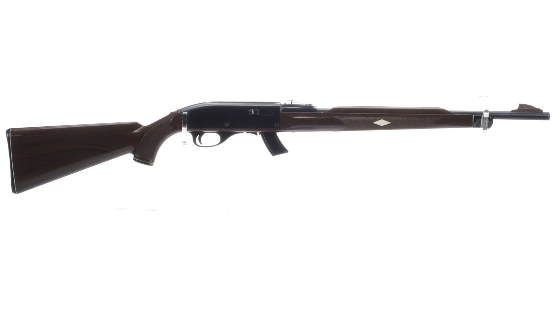
Nylon 77 and Mohawk 10C (box magazine). The 77 of 1970 swapped the butt tube for a detachable box magazine under the action, five rounds at first and ten later; the Mohawk 10C was the same rifle with the ten-round magazine standard.84 The change goes deeper than the magazine. Simmons: “the bolts of the two types of rifles are very different and can’t be interchanged. The 77 bolt has a feed rib at the bottom and this rib is not found on a 66. Also, the contour of the ejectors on the two rifles change.”4 The magazines themselves are almost all plastic, “save for only a small metal ‘U’ clip that holds the top rear of the magazine lips together”. The Nylon 77 folder describes removing it by “depressing rear of magazine latch thumbpiece”. Its safety “is designed to separate trigger from action when in SAFE position. Trigger in SAFE position is free swinging and cannot fire rifle.”8
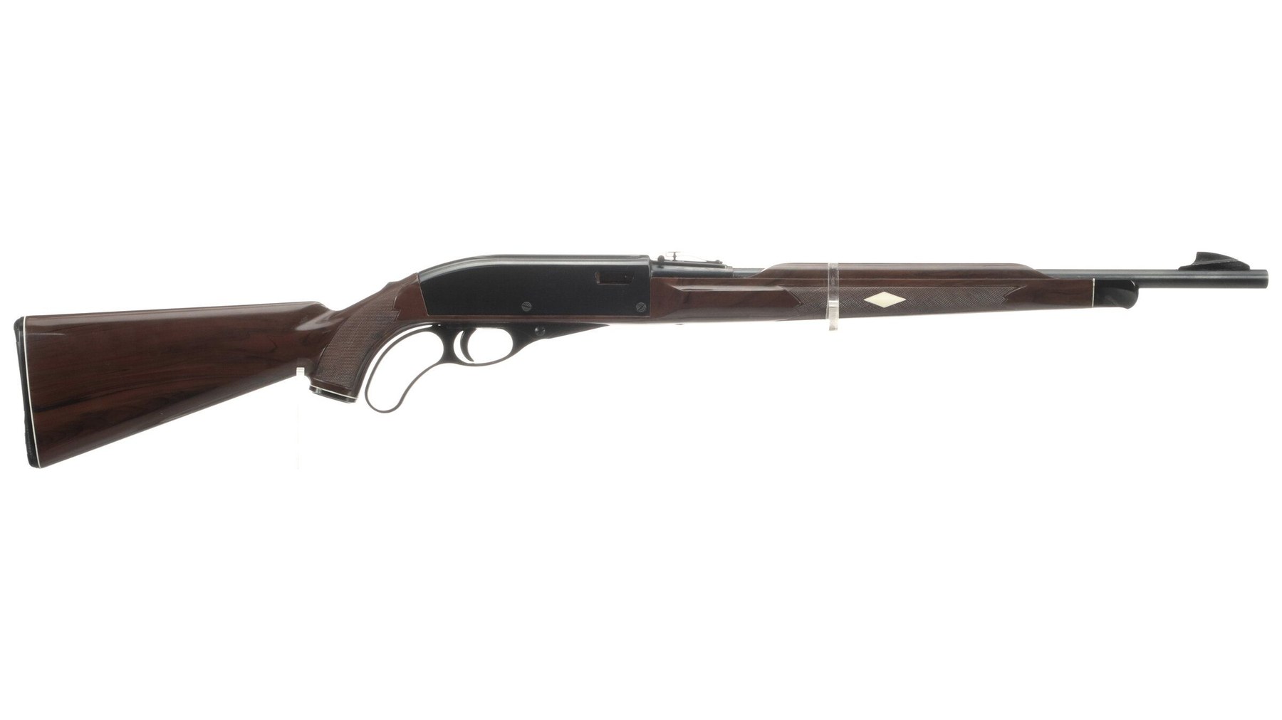
Nylon 76 Trailrider (lever action, locked breech). The Nylon 76 is the family’s engineering surprise. Remington, Simmons writes, “had to work with what they had, using the Model 66 stock and bolt. They came up with a locked-breech lever-action rifle starting from an autoloader. They created a very short stroke—about 30 degrees—lever action with a rack and pinion reminiscent of the old Bullard lever-action rifle.” Only “the barrel, the magazine, and the sights were the only parts borrowed as-is from the Model 66”.4 Remington’s patent had anticipated it: locking “the breech bolt directly to the rear end of the barrel will permit the production of positively locked breech loading firearms”.1 The Nylon 76 fed from the same fourteen-round butt tube. Rock Island Auction’s lot text calls it “the only lever action design manufactured by Remington”, which is true of Remington’s own designs of the period; it is not a claim checked against every later Remington-branded product.
Nylon 10, 11 and 12 (bolt actions). The bolt guns used a Nylon-style stock and sights “and there the similarity ended”, Simmons writes. “Strangely, with Remington’s great interest in interchangeability, none of the bolt-action rifles shared parts with the Model 66 that could have been the same”, down to the white diamond over the stock screw, which is a different part.4 The Nylon 10 is a single shot that, Simmons notes, “went on safety each time it was cocked”. There was also a smoothbore version for .22 shot cartridges, which Remington’s model history lists as the Nylon 10SB, “barrel marked 22 CAL Smoothbore”.9 The Nylon 11 feeds from a detachable steel box magazine of six rounds, later ten. The Nylon 12 feeds from a tube under the barrel. All three take .22 Short, Long and Long Rifle.94
References
Footnotes
-
W. E. Leek and C. H. Morse, “Firearm Having Receiver Bearing Surfaces of Synthetic Resinous Material”, US Patent 3,023,527, issued 6 March 1962 (original application filed 5 January 1956). https://patentimages.storage.googleapis.com/pdfs/US3023527.pdf , retrieved 2026-09-19. Reference numerals in quotations are the patent’s, not Remington’s parts-list view numbers. ↩ ↩2 ↩3 ↩4 ↩5 ↩6 ↩7 ↩8 ↩9 ↩10 ↩11 ↩12 ↩13
-
Remington Arms Company, Nylon 66 exploded view (sheet RF 21) and parts list (sheet RF 22), in the Nylon 66 information packet. Archived PDF: https://web.archive.org/web/20110910092323/http://www.remington.com:80/~/media/Files/Owners-Manuals/Nylon%2066.ashx , retrieved 2026-09-19. View numbers in parentheses in the text are Remington’s. ↩ ↩2 ↩3 ↩4 ↩5 ↩6 ↩7
-
Roy Marcot, “The Remington Nylon 66”, American Rifleman, 27 August 2009. Archived: https://web.archive.org/web/20150303174642/http://www.americanrifleman.org:80/articles/2009/8/27/the-remington-nylon-66 , retrieved 2026-09-19. ↩ ↩2 ↩3 ↩4 ↩5 ↩6 ↩7 ↩8 ↩9 ↩10
-
Donald M. Simmons, “Those Plastic Remingtons”, The Gun Digest, 45th Edition (1991). Scan archived at https://web.archive.org/web/20100524123435/http://www.nylonrifles.com/Nylonpdf/PlasticRems.pdf , retrieved 2026-09-19. ↩ ↩2 ↩3 ↩4 ↩5 ↩6 ↩7 ↩8 ↩9 ↩10 ↩11 ↩12 ↩13 ↩14 ↩15 ↩16 ↩17 ↩18
-
Remington Arms Company, “Nylon 66 · 22 Caliber Automatic Rifle” instructions, in the same Remington Nylon 66 information packet (archived PDF linked in the parts-list note above). ↩ ↩2 ↩3 ↩4 ↩5 ↩6 ↩7 ↩8 ↩9 ↩10
-
H. W. Young, “Fire Control Mechanism for Reciprocating Bolt Firearms”, US Patent 3,027,811, filed 29 April 1958, issued 3 April 1962. https://patentimages.storage.googleapis.com/pdfs/US3027811.pdf , retrieved 2026-09-19. ↩
-
DuPont, “Minlon and Zytel Design Information – Module II” (2001), section 1. Archived: https://web.archive.org/web/20151016093431/http://www.dupont.com/content/dam/dupont/products-and-services/plastics-polymers-and-resins/thermoplastics/documents/Zytel/Minlon%20Zytel%20Design%20Info%20Module%202.pdf . ↩
-
Remington Arms Company, “Nylon 77 Automatic Rifle · Instruction Folder and Parts List” (Ilion, New York). Archived PDF: https://web.archive.org/web/20110909062648/http://www.remington.com:80/~/media/Files/Owners-Manuals/Nylon%2077.ashx , retrieved 2026-09-19. ↩ ↩2 ↩3
-
Remington Arms Company, model-history pages for the Nylon 10, 11 and 12. Archived 13 November 2013: https://web.archive.org/web/20131113184302/http://remington.com/en/products/archived/rimfire/bolt-action/nylon-10.aspx (and nylon-11.aspx, nylon-12.aspx), retrieved 2026-09-19. ↩ ↩2
Comments (0)