Ruger Mark III & Mark IV · Volume 3
How It Works — The Tube, the Bolt, and the Pin That Holds It Together
Blowback, the three-job bolt stop pin, the fire-control group, and what the Mark III added and the Mark IV changed
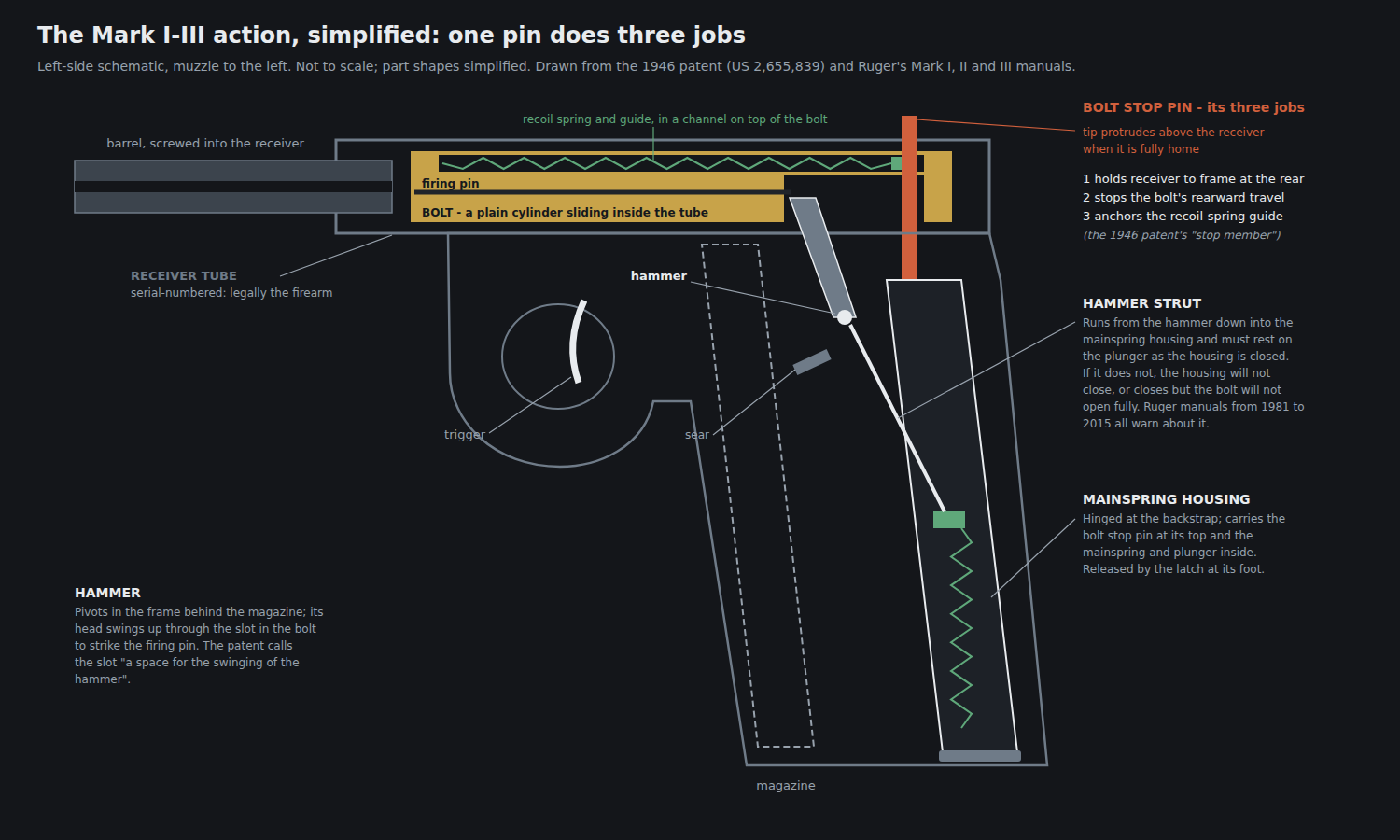
A Ruger .22 automatic has fewer ideas in it than almost any other pistol of its class, and every one of them is visible in the 1946 patent. This volume takes the mechanism apart in the order a gunsmith would meet it: the assemblies, the operating principle, the receiver and bolt, the pin that holds the receiver on, the fire-control group in the frame, and then the additions and changes of the Mark III and Mark IV. Takedown procedure is Volume 4’s subject and is not repeated here; this volume explains why the procedure is what it is.
Part names are Ruger’s, taken from the parts lists in its Mark II, Mark III and Mark IV manuals. Where a mechanism is inferred from a parts list or from a supplier’s instructions rather than described in a Ruger document, the text says so.
3.1 Five assemblies, one of which is the firearm
Every generation divides into the same five assemblies:
- The barrel/receiver assembly — the round receiver tube with the barrel screwed into it and the sights fixed to one or the other.
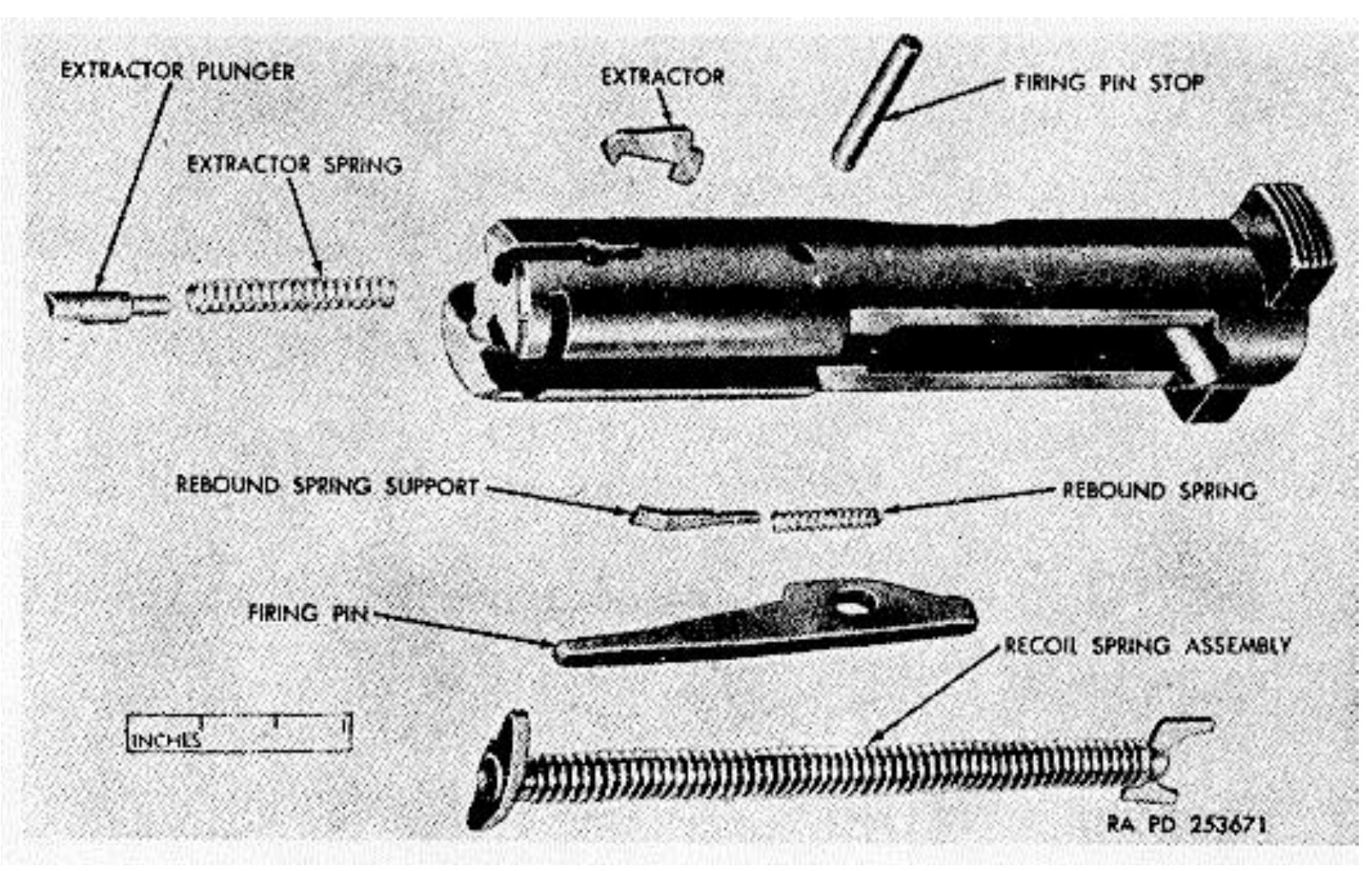
- The bolt assembly — the bolt, firing pin, rebound spring and support, firing pin stop, extractor with its plunger and spring, and the recoil spring assembly.
- The grip frame — carrying the trigger, sear, hammer, disconnector, safety, magazine catch and, from the Mark II, the bolt hold-open.
- The mainspring housing assembly — on the Mark I–III, a hinged backstrap unit carrying the mainspring and, at its top, the bolt stop pin. The 1959 Army manual forbids its disassembly: “No disassembly of the mainspring housing assembly is authorized.”1
- The magazine.
The first of these is the firearm in law. Ruger’s Mark III manual is explicit: “Because it is a serial-numbered component, the RUGER® MARK III pistol barrel/receiver assembly is defined as a ‘firearm’ by Federal Law and is not offered for sale separately.” The Mark IV manual says the same of its barrel/receiver assembly, which “is not sold as a separate component.”23 Everything that makes the pistol fire — trigger, sear, hammer, safety — is in the grip frame, which is not the firearm. That division is what allowed Ruger to recall the Mark IV’s fire-control parts by asking owners to post only the grip frame (Volume 5), and it is why a replacement upper from an aftermarket maker must be transferred through a dealer while a replacement trigger can be bought over the counter (Volume 7).
3.2 Blowback, and why nothing more is needed
The Ruger is an unlocked, straight-blowback pistol. Ruger’s manual describes the cycle in one sentence: “When the pistol is fired, the same gas pressure that drives the bullet forward also acts through the cartridge case to push the bolt to the rear. That action causes extraction and ejection of the fired cartridge case.”2 Nothing locks the bolt to the barrel. The bolt’s mass and the recoil spring are what keep it closed long enough for pressure to fall, and the .22 Long Rifle develops low enough pressure that a bolt small enough to fit inside a pistol receiver is sufficient.
The practical consequences are the ones every blowback .22 shares. Ammunition that is weaker than the recoil spring expects will short-cycle; a heavier bolt or spring shifts the balance the other way. Ruger’s manuals approve standard- and high-velocity .22 Long Rifle “manufactured to U.S. Industry Standards,” reject .22 Short and .22 Long, and discourage shot shells.2 The current Mark IV manual adds a caution the Mark III’s does not carry: “Certain types of high velocity ammunition may show bulges or splits when examining the spent cases. If this occurs, discontinue using the ammunition.”3 How .22 ammunition behaves in a pistol-length barrel, and which loads suit which guns, is the subject of the .22 Rimfire dive’s Volumes 4 and 9 and is not re-derived here.
3.3 Receiver and bolt
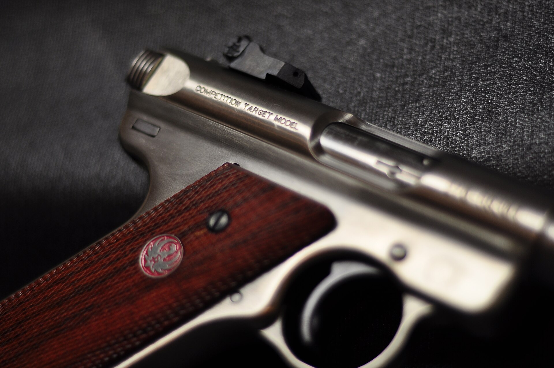
The receiver is a tube. The patent specified “stock tubing,” and the round receiver and round bolt have survived every generation; the 2016 Mark IV press release calls them “the legendary, one-piece barreled receiver and internal cylindrical bolt construction.”45 Because the bolt moves inside the receiver and the sights are on the receiver and barrel, the sights never move relative to the bore. Ruger’s spec sheets present this as an accuracy argument: “Internal cylindrical bolt construction ensures permanent sight to barrel alignment and higher accuracy potential than conventional moving slide designs.”6
The barrel is screwed into the receiver and is not user-removable.7 On the Mark III and Mark IV 22/45 Lite, the barrel is instead a thin tube tensioned inside a ventilated aluminium receiver and held by a nut at the muzzle, and Ruger’s manuals are emphatic about that nut: it “is epoxied and torqued in place at the factory … and should not be removed under any circumstance.”23
The bolt is cocked by pulling back on its two serrated ears at the rear. Inside it:
- The recoil spring and its guide ride in a channel along the top of the bolt and lift out as a unit; the Army’s 1959 manual begins bolt disassembly with “Lift off the recoil spring assembly from the top of the bolt.”1 Keefe describes the spring and guide as “recessed into the bolt’s top … captive.”7
- The firing pin is retained by a small cross-pin, the firing pin stop, with a rebound spring and support behind it.2 That small pin is the subject of the most serious warning in every Ruger reassembly procedure. The Mark III manual: “BE CERTAIN that the firing pin stop … is in the bolt … Without this pin, the first time the trigger is pulled on an assembled pistol, the firing pin will fly forward so far as to irreparably dent the rear end of the chamber of the barrel, making the pistol useless.”2 The 1981 Mark I manual says the same of dry-firing without it: the dent renders “the Barrel-Receiver Assembly useless and beyond repair.”8 Because the barrel and receiver are one serialized assembly that Ruger does not sell separately, a peened chamber mouth on a Ruger is not a barrel replacement; it is a factory repair.
- The extractor is on the right of the bolt face, held by a spring-loaded plunger.71
- The slot. The rear of the bolt carries the patent’s “upright longitudinal guide slot which serves a triple function; namely, a space for the swinging of the hammer, a guide means for retaining the bolt in a non-turning position, and a means for engaging a stop member to limit the movement of the bolt.”4 The hammer head rises through it to strike the firing pin; the bolt stop pin passes through it; and because the pin passes through it, the bolt cannot rotate in its tube.
The ejector in the original design was fixed to the frame: the patent makes it the upper front edge of the hammer housing, and Keefe describes the first pistols’ “fixed ejector … riveted to the frame.”47 Ruger’s Mark IV parts list places the ejector and its rivet among the barrel/receiver assembly components.3 No Ruger document consulted states when or why it moved; the parts list is the only evidence, and it is stated as such.
3.4 The bolt stop pin
The part that defines the Ruger is not the bolt but the pin that stops it. The patent’s “stop member … is inserted through the slot and … serves to effect an engagement between the receiver and the grip member, thereby securing those members together at the rear and forming an unyielding block for stopping the bolt at the end of its ejection stroke. The stop member may also be used as a support for the action spring.”4
In the production pistols this is the bolt stop pin, and it is mounted at the top of the mainspring housing. It does three jobs at once:
- It holds the receiver to the frame at the rear. At the front, the receiver hooks over a lug on the frame — “the lug (formed by the top end of the trigger guard)” in the Mark I manual, “the square lug” in the Mark II and III manuals.892 At the rear, only the pin holds them together.
- It stops the bolt. When the bolt recoils, the front end of its slot meets the pin, and the pin stops it.
- It anchors the recoil spring. The Mark I manual describes the pin, as it is pushed up into place, having to “pass by the rear end of the recoil spring guide, camming the guide forward to put initial tension into the recoil spring.”8 The Army’s manual says the same thing more bluntly: “The pin should be forced past the recoil spring guide.”1
The pin passes through the frame, the receiver and the bolt’s slot, in that order, and its tip is meant to show above the top of the receiver when it is fully home — “until the tip of the pin protrudes beyond the top of the receiver,” in the Mark III manual’s words.2 A part that has to go through three components, compress a spring on the way, and carry a hinged housing behind it is the reason the Mark I–III reassembly is hard. Volume 4 sets out Ruger’s procedures; the difficulty is already visible here.
3.5 Hammer, strut and mainspring housing
The hammer pivots in the frame behind the magazine. Its head swings up through the slot in the bolt to strike the rear of the firing pin. A hammer strut hangs from it and runs down into the mainspring housing, where it bears on a plunger sitting on the mainspring (Ruger’s parts lists call it the hammer spring).423 In the patent, that same spring also operated the heel magazine catch — “the hammer spring accordingly serves a double function; it operates the hammer and the magazine catch.”4
The strut is the part the reassembly turns on. When the housing is swung shut, the strut’s lower end must seat on the plunger. The Mark I manual:
“It is essential that the hammer strut comes to rest on the mainspring plunger as the housing is closed. … If the hammer strut does not contact the mainspring plunger as the housing is swung shut, it will either be impossible to complete the closure of the housing or the housing may be closed but it will be impossible to draw the bolt all the way back.”8
The Mark III manual describes the same seat as “the oval-shaped cut inside the mainspring housing” and adds a failure the older manual does not: the strut can be “trapped behind the crosspin” in the grip frame, which prevents the hammer being positioned at all.2 Its troubleshooting line puts the whole mechanism in one sentence: “it is essential that the hammer must be in its vertical, uncocked position as the mainspring housing is swung shut. If the housing is excessively difficult to close, the hammer is probably cocked.”2 The manuals do not explain why. The mechanical reading is straightforward: cocking the hammer drives the strut down against the mainspring, so closing the housing over a cocked hammer means compressing that spring by hand through the housing — which is the “excessively difficult” closure the manual describes. That explanation is inferred from the parts, not stated by Ruger.
One more detail in the Mark III parts list matters to anyone changing grips. The hammer pivot pin is held in the frame by the left grip panel: “The Hammer Pin (Key No. 44) is prevented from drifting out of the left side of the Grip Frame by contact with the inner surface of the left Grip Panel. Therefore, be certain that the clearance cut in the left Grip Panel is the correct depth to maintain the Hammer Pivot fully seated in the Grip Frame.”2 An aftermarket left panel with too deep a relief lets the hammer pin walk.
3.6 Trigger, sear and disconnector
The trigger pivots in the frame and acts on the sear through a bar that passes around the magazine well. The patent describes a trigger rod “in the form of a loop passing on both sides of the magazine,” with “inclined surfaces … for connection with a cam surface on the bolt which is a disconnecter for the trigger.”4 When the bolt recoils, its cam presses the trigger bar down out of engagement with the sear, so that the hammer cannot fall again until the trigger has been released and the bar has reset. That is what makes the pistol semi-automatic. Ruger’s later parts lists name the parts as the disconnector assembly (Mark II and III) and the trigger bar with its pivot pin (Mark IV).923
The sear holds the cocked hammer; the Mark III parts list gives it a sear spring and a separate sear spring stop pin, and the Mark IV list a sear, sear spring and sear pivot pin.23 Every Volquartsen trigger kit for these pistols replaces the hammer and sear as a matched pair along with the disconnector and trigger (Volume 7), which is the clearest evidence of where the trigger pull is made.
The Mark I Target’s trigger pull is recorded in the Army’s 1959 manual as 2¼ to 3¼ pounds.1 No Ruger spec sheet consulted for the Mark III or Mark IV gives a trigger-pull figure, and none is quoted here.
3.7 The safety
On every generation the manual safety locks the sear, and on every generation it can be applied only when the hammer is cocked, which makes it a cocking indicator: “Because the safety cannot be moved to its ‘on’ (S) position unless the hammer is cocked, the safety therefore serves as a cocking indicator.”92
What the safety does not do changed with the Mark II. The patent’s safety “locks the sear and also the bolt preventing the bolt from being pulled rearwardly,” and the 1959 Army manual says the Mark I’s safety “also can be used to lock the bolt in the rear.”41 From the Mark II onward, “the bolt can be manually retracted and released when the safety is ‘on’ … This feature allows the pistol to be loaded or unloaded when the safety is ‘on’.”92
Every Ruger manual consulted from the Mark II on carries the same warning about a half-applied safety: “Putting the safety between ‘S’ and ‘F’ can result in the pistol firing when the trigger is pulled … NEVER PUT SAFETY 1/2 ON.”923 On the Mark I–III the safety is a button sliding up and down in a slot at the left rear of the frame; on the Mark IV it is an ambidextrous lever, and a white dot shows when it is on and a red dot when it is off.73 Volume 5 shows how the Mark IV’s lever came to be recalled for a different half-on failure.
3.8 Two parts called “bolt stop”
Ruger’s documents use “bolt stop” for two unrelated parts, and the Mark III manual goes out of its way to separate them: the hold-open components “are for holding open the bolt and are not functionally related to the Bolt Stop Pin and Bolt Stop Pin Pivot. These two later components are attached to the Mainspring Housing Assembly.”2
- The bolt stop pin is the three-job pin described above.
- The bolt stop (with its plunger, spring and thumbpiece) is the hold-open, added with the Mark II. When the last round has been fired, “the magazine follower presses the slide stop upward,” in the manual’s wording — the text still says “slide,” a survival from older manuals, though there has never been a slide on this pistol — and the bolt is held open.2 It can be pushed up by hand with the bolt retracted, and released by drawing the bolt back slightly and pressing the thumbpiece.
The hold-open is only lightly retained. Every manual from the Mark II on warns that it is “spring-loaded or detented in position. Therefore, when there is a loaded magazine in place and the pistol is jarred, the bolt may fly forward and chamber a cartridge.”923 The aftermarket “automatic” bolt releases discussed in Volume 7 exploit exactly this light retention: they are shaped so that a slight rearward pull on the bolt lets it fly forward without touching the thumbpiece.
3.9 The cycle, step by step
With the parts named, the full cycle of a Mark I–III can be followed from a loaded magazine to the next shot. The sequence below is assembled from the 1946 patent, Ruger’s manuals and the 1959 Army manual, each cited at the step it supports; the Mark IV differs only where noted.
- Cocking and chambering. Pulling the bolt ears fully back “cocks the hammer and must be done before the safety can be put on.” The bolt’s slot rides over the hammer and pushes it down and back; the hammer strut drives the plunger down and compresses the mainspring in the housing; the sear catches the hammer. The recoil spring, compressed against the bolt stop pin, drives the bolt forward when it is released, and the bolt face strips the top cartridge from the magazine and pushes it into the chamber.24 With a loaded magazine in place the hold-open does not engage: “If a loaded magazine is inserted in the pistol when the bolt is closed and the bolt is then retracted fully, the bolt stop will not automatically hold open the bolt.”2
- Firing. With the safety off, pulling the trigger moves the trigger bar, which releases the sear; the mainspring, acting through the strut, drives the hammer up through the slot in the bolt against the rear of the firing pin, which strikes the rim.42 On a Mark III or IV the magazine disconnect permits this only when a magazine is seated.23
- Recoil and extraction. “The same gas pressure that drives the bullet forward also acts through the cartridge case to push the bolt to the rear,” and the extractor on the right of the bolt face draws the fired case out of the chamber.21
- Disconnection. As the bolt starts back, its cam presses the trigger bar down out of engagement with the sear — the patent’s “disconnecter for the trigger” — so that the hammer cannot follow the bolt forward while the trigger is still held.4
- Ejection and re-cocking. The moving bolt rides over the hammer again and re-cocks it against the sear. The case strikes the fixed ejector and leaves through the port on the right.47
- The stop. The front of the slot in the bolt meets the bolt stop pin, which arrests the bolt and, through the frame, transfers the blow to the grip frame; the recoil spring, anchored on the same pin, is now fully compressed.48
- Return and feed. The spring drives the bolt forward; it strips and chambers the next round. When the trigger is released, the trigger bar rises back into engagement with the sear and the pistol is ready to fire again.42
- Last round. When the magazine is empty “the magazine follower presses the slide stop upward,” in the manual’s words, and the hold-open catches the bolt to the rear (Mark II onward; the Standard and Mark I have no automatic hold-open).28
3.10 What the Mark III added inside
The loaded-chamber indicator is a small spring-loaded lever set into the left side of the receiver — Ruger’s parts list gives a loaded chamber indicator, spring and pin.2 A cartridge in the chamber pushes it outward, so that “the rearmost portion of the loaded chamber indicator should protrude from the left side of the receiver, and a red dot also should be visible on the forward top portion.”2 Its pin is loose enough when the receiver is off the frame that the Mark III manual’s reassembly instructions include a check that it “has not fallen out of the receiver.”2
The magazine disconnect is a magazine disconnector and spring in the grip frame, and it works with the magazine. The Mark III magazine “has a trigger interlock window and protrusion,” and Ruger’s manual says the M10MKIII is “the only magazine that should be used in RUGER® MARK III pistols because it is designed to correctly function the bolt stop and magazine disconnect.”2 With the magazine out, “this device prevents the trigger from being pulled.”2 Ruger does not describe the internal linkage. One piece of indirect evidence locates it: Volquartsen’s Mark II/III trigger kit, which removes the disconnect, includes a Mark II-pattern hammer bushing “that must be used when eliminating the magazine disconnect feature in the Ruger MKIII.”10 The disconnect therefore involves parts at the hammer pivot, not only in the trigger. That is an inference from a supplier’s parts list, and it is stated as one.
The internal lock is in the mainspring housing. Ruger’s parts list gives a lock pin, a spring back-up pin, and a lock detent plunger and spring among the housing parts.2 Turning the key “about 1 3/4 of a rotation” locks the manual safety in the on position; the pistol “must be cocked to engage the safety,” so it must be cocked to be locked.2
All three additions are in the Mark III’s receiver or grip frame, and all three added a condition to the pistol’s handling. None changed the operating cycle.
3.11 What the Mark IV changed inside
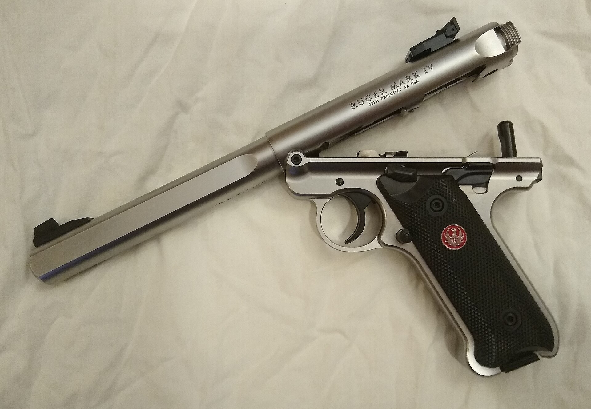
The Mark IV kept the tube, the bolt, the hammer and strut, the mainspring and the bolt stop pin — all five appear in its parts list.3 What changed is how the receiver is held on.
- A pivot at the front. “There is a new pivot screw at the top front of the frame that aligns with a corresponding semi-circular notch at the front of the receiver’s underside,” Keefe wrote, and “there is still a lug on the frame (screwed in place) that mates against the underside of the receiver at the front.”7 Ruger’s parts list shows a frame lug and a receiver frame screw.3
- A latch at the rear. “The takedown button has a rear-facing lug that engages a notch cut into the underside of the receiver’s rear … A fixed lug at the front, and another sliding one at the rear surrounding the bolt-stop pin … keep the gun together. Depressing the take-down button pulls the rear lug out of engagement.”7 Ruger’s manual has the user “depress the take-down button located just below the rear of the bolt” and “tilt the barrel downward so that it clears the bolt stop pin.”3
- The bolt stop pin stays in the frame. On the Mark I–III it was withdrawn downward with the housing every time the pistol was stripped. On the Mark IV the receiver lifts off over it, and goes back down onto it — “Rotate the barrel/receiver assembly down on to the bolt-stop pin in the grip frame,” the reassembly instruction reads.3 The strut never has to be re-seated because the housing never comes out.
The other internal changes are listed in Ruger’s release as “changes to the hammer, sear, bolt and firing pin for smoother, more reliable feeding,” and “a redesigned magazine disconnect safety,” without further detail.5 The parts list adds a magazine assist — the spring-loaded ejector under the right grip panel that makes the magazine “drop free.” The manual warns that it is “under spring tension and should be covered with your hand when removing the grip panel.”3 The ambidextrous safety can be reduced to left-side only by removing the right lever with a 1/16-inch hex key and fitting a supplied spacer.3 And the frame itself is now “a one-piece grip frame that is precision CNC-machined from a solid piece of stainless steel or aluminum,” in place of the welded pressings of the patent.5
Volume 4 sets the two systems side by side in a drawing and follows each through Ruger’s own procedure.
3.12 Dry-firing
The manuals’ positions on dry-firing differ by generation, and the difference is worth knowing before the pistol is used for trigger practice.
- Mark I (1981 manual). The only statement found concerns the firing pin stop: without it, “the first time the pistol is dry fired … the firing pin will be free to move forward to the extent that it will dent the rear face of the chamber.”8
- Mark III (2015 manual). “The pistol can be dry fired as long as the firing pin stop is in place.”2
- Mark IV (current manual). “This firearm can be dry fired in moderation to perform basic function checks without causing damage or premature wear to its internal components. CAUTION: A snap cap should be used for extensive dry-fire practice.”3
The Mark IV manual also prints a function check that tests the disconnect and the safety together: with no magazine and the safety off, “the trigger should move slightly rearward and stop. The hammer should not fall”; with an empty magazine and the safety on, the hammer should not fall; with an empty magazine and the safety off, it should; and the safety “should NOT move to ‘SAFE’ with the hammer in the fired position.”3 It is a useful routine for any Mark III or IV after reassembly — and, as Volume 7 notes, the first step of it no longer applies once a kit that removes the magazine disconnect has been fitted.
References
Footnotes
-
Departments of the Army and the Air Force, TM 9-1005-226-14 / AFM 50-11, 20 July 1959, paras. 3b, 5b, 46, 66, 67; Wikimedia Commons File:TM-9-1005-226-14.pdf, consulted 2026-09-19. ↩ ↩2 ↩3 ↩4 ↩5 ↩6 ↩7
-
Sturm, Ruger & Co., Instruction Manual for Ruger Mark III … Autoloading Pistols, © 2015, code AP & KAP 9/15 R15, https://ruger-docs.s3.amazonaws.com/_manuals/markIII.pdf , consulted 2026-09-19 — pp. 10–14, 17–20, 23–27, 33, 35–38. ↩ ↩2 ↩3 ↩4 ↩5 ↩6 ↩7 ↩8 ↩9 ↩10 ↩11 ↩12 ↩13 ↩14 ↩15 ↩16 ↩17 ↩18 ↩19 ↩20 ↩21 ↩22 ↩23 ↩24 ↩25 ↩26 ↩27 ↩28 ↩29 ↩30 ↩31 ↩32 ↩33 ↩34 ↩35
-
Sturm, Ruger & Co., Instruction Manual for Ruger Mark IV … Autoloading Pistols, code PM1179, © 2026, https://www.ruger.com/dataProcess/manual/fetch.php/ms/40160/manual_40160.pdf , consulted 2026-09-19 — pp. 11–14, 17, 21–24, 27, 31, 34–36. ↩ ↩2 ↩3 ↩4 ↩5 ↩6 ↩7 ↩8 ↩9 ↩10 ↩11 ↩12 ↩13 ↩14 ↩15 ↩16 ↩17 ↩18 ↩19
-
W. B. Ruger, US Patent 2,655,839, “Blowback Autoloading Pistol,” filed 5 November 1946, issued 20 October 1953, https://patents.google.com/patent/US2655839A/en , consulted 2026-09-19. ↩ ↩2 ↩3 ↩4 ↩5 ↩6 ↩7 ↩8 ↩9 ↩10 ↩11 ↩12 ↩13 ↩14
-
Sturm, Ruger & Co., “Ruger Perfects Rimfire — Again: Introducing the One-Button Takedown Mark IV,” 22 September 2016, https://ruger.com/news/2016-09-22.html , consulted 2026-09-19. ↩ ↩2 ↩3
-
Sturm, Ruger & Co., spec sheet, Mark III Target model 10101, as archived 14 January 2016, http://web.archive.org/web/20160114101901/http://www.ruger.com:80/products/markIIITarget/specSheets/10101.html?buy=1 , consulted 2026-09-19. ↩
-
Mark A. Keefe IV, “Mark IV: The Ruger Evolution,” American Rifleman, 20 March 2017, https://www.americanrifleman.org/articles/2017/3/20/mark-iv-the-ruger-evolution/ , consulted 2026-09-19. ↩ ↩2 ↩3 ↩4 ↩5 ↩6 ↩7 ↩8
-
Sturm, Ruger & Co., Instruction Manual for Ruger Mark I Target Model and Standard Model Automatic Pistols, code A-7-81, https://ruger-docs.s3.amazonaws.com/_manuals/markI.pdf (scanned; text by OCR), consulted 2026-09-19. ↩ ↩2 ↩3 ↩4 ↩5 ↩6 ↩7
-
Sturm, Ruger & Co., Instruction Manual for Ruger Mark II Autoloading Pistols, code AP & KAP 1/03 C R8, https://ruger-docs.s3.amazonaws.com/_manuals/markII.pdf , consulted 2026-09-19. ↩ ↩2 ↩3 ↩4 ↩5 ↩6
-
Volquartsen Firearms, “Accurizing Kit for the Ruger MK II or MK III Pistol,” https://volquartsen.com/products/354-accurizing-kit-for-the-ruger-mk-ii-or-mk-iii-pistol , consulted 2026-09-19. ↩
Comments (0)