LeMat Revolver · Volume 4
How It Works — Two Barrels, One Hammer and a Cylinder That Turns on a Gun Barrel
The layout in section, the lockwork part by part using the maker's own parts names, the hammer head that chooses the barrel, the two ways the cylinder is held in line, and why the loading lever broke
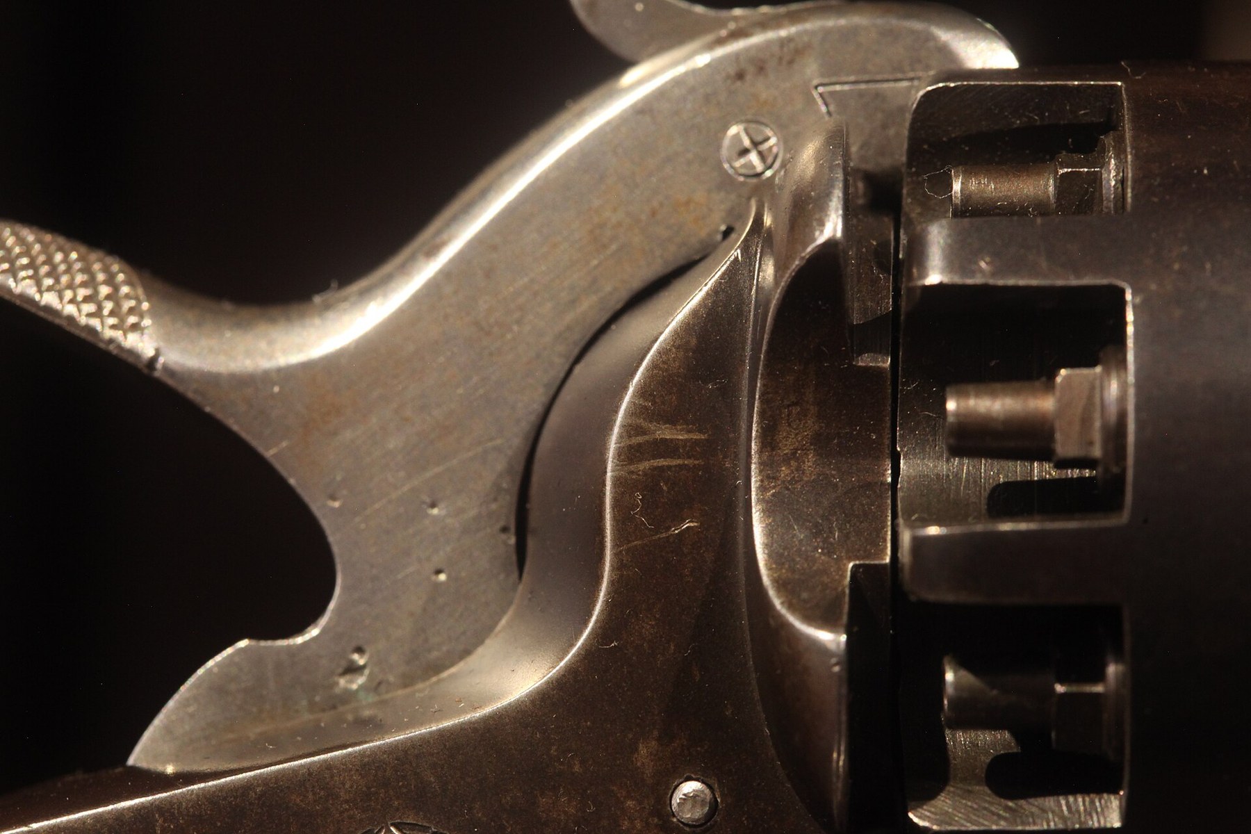
The LeMat is a single-action percussion revolver of the 1850s with two additions: its cylinder pin is a gun barrel, and its hammer has a head that can be turned to fire that barrel. Everything else — the hand that turns the cylinder, the trigger and sear, the mainspring, the cap-and-ball chambers — is the ordinary technology of its decade. This volume describes the mechanism as the patents describe it, as the catalogue descriptions of surviving guns record it, and as the instruction manual of the gun’s only current maker names its parts.
No period armourer’s manual for the LeMat was found. The Pietta manual’s parts list for its reproduction is the only published parts nomenclature located, and it is used here for names, with differences between the reproduction and the originals noted where the sources record them.
4.1 The layout in one picture
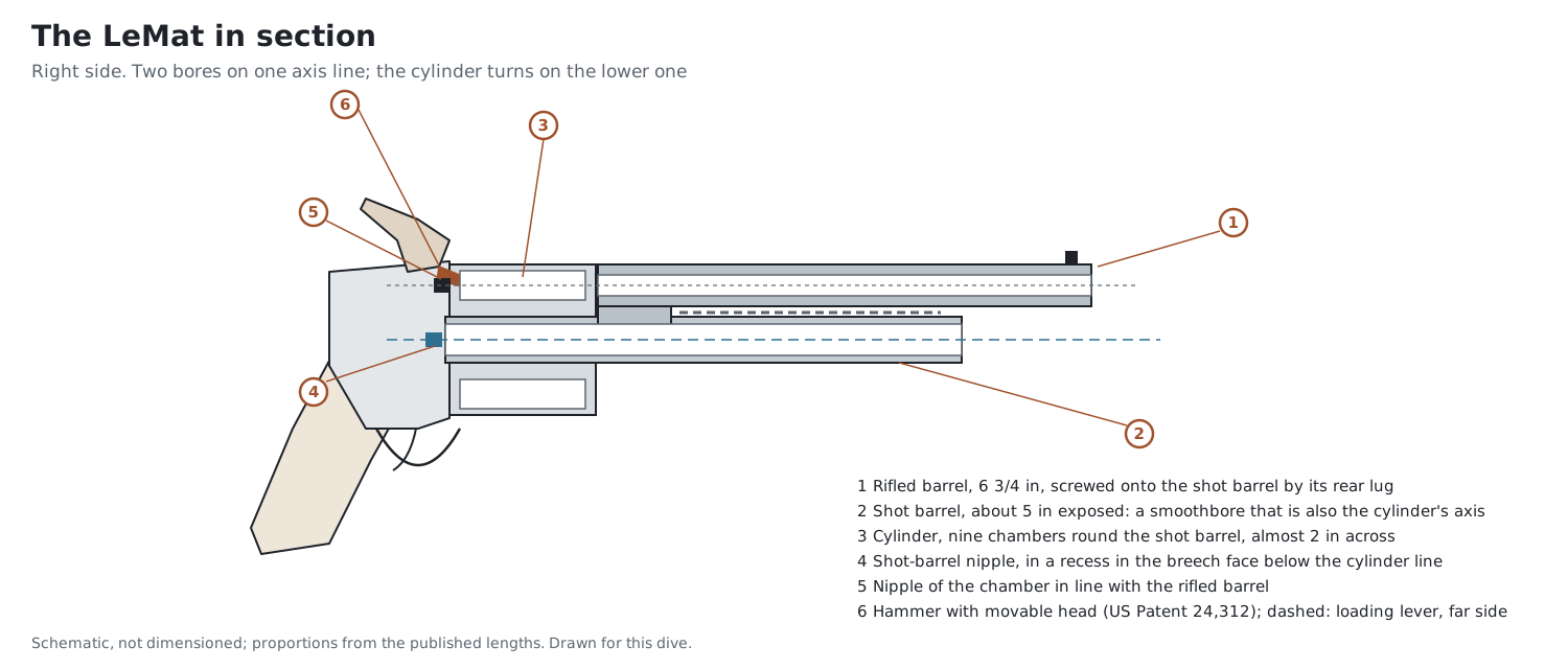
Three geometrical facts determine the whole design.
- The shot barrel is the cylinder’s axis. In a Colt the cylinder turns on a solid steel arbor screwed into the frame. In the LeMat, the arbor is bored out and is itself a barrel — “a shot-barrel instead of the solid central cylinder,” in the 1856 patent.1 Its bore therefore sets the minimum inside diameter of the cylinder, and the nine chambers must sit around it.
- Nine chambers need a big cylinder. With a .63 in hole in the middle, nine .42 in chambers can only be fitted on a large circle. Bodinson measures the reproduction’s cylinder at “almost 2 inches in diameter.”2 The weight and bulk that every user complains of follow from that.
- The two barrels are stacked on the axis line. The rifled barrel sits at the top of the cylinder’s circle, where the hammer strikes; the shot barrel sits at its centre, directly below. So the hammer must be able to reach two places: the cap at the top of the cylinder, and a cap at the centre of the breech face. That is the problem the movable hammer head solves.
4.2 The parts, by the maker’s names
Pietta’s manual lists 55 numbered parts for its LeMat. The list is reproduced here in groups, because it is the only published naming of the gun’s parts and because it is what a reader ordering spares will need. The exploded drawing that accompanies it in the manual is Pietta’s copyright and is not reproduced.3
Table 1 — The parts, by the maker's names
| Group | Pietta part numbers and names |
|---|---|
| Barrels | 7 front sight · 8 barrel · 14 shot barrel .20 ga. · 15 breech plug · 13 nipple |
| Barrel attachment | 9A takedown pin (Army/Navy) · 9B takedown lever (Cavalry) · 9C takedown lever spring · 10 takedown pin spring · 11 takedown pin spring screw · 25 takedown lever pin |
| Loading gear | 1 shot barrel ramrod · 2 loading lever tube · 3 loading lever · 4 plunger screw · 5 plunger · 6 loading lever screw · 50 loading lever retaining spring screw · 51 loading lever retaining spring |
| Cylinder | 12 cylinder · 13 nipple (nine on the cylinder) |
| Frame | 23 frame · 24 side plate · 17 side plate nut |
| Hammer and selector | 32 hammer · 18 hammer screw · 31 hammer nose · 55 hammer nose pin · 35 hammer nose screw · 34 hammer nose spring · 33 hammer nose spring screw |
| Trigger and cylinder stop | 26 trigger · 27 trigger pin · 22 trigger spring · 19 cylinder stop · 20 cylinder stop return spring · 21 cylinder stop retaining nut · 36 cylinder stop tension spring · 37 cyl. stop tension spring screw · 54 cylinder stop screw · 16 tension spring adj. screw |
| Hand | 40 hand & spring · 41 hand bracket · 42 hand bracket screw |
| Mainspring | 43 mainspring · 44 mainspring screw · 38 mainspring retainer · 39 mainspring retainer pin |
| Grip and guard | 28 triggerguard · 29 front triggerguard screw · 30 rear triggerguard screw · 45 grip screw · 46 right grip locking nut · 47 left grip nut · 48–49 left/right grip · 52 lanyard base · 53 lanyard ring |
Source: 3
Two points in the list are worth noticing. The breech plug (15) is a separate part: on the reproduction, the shot barrel’s breech is closed by a screwed plug, and the shot barrel’s nipple is a separate part (13) like the cylinder’s. And the cylinder stop has five associated parts and an adjusting screw — a great deal of hardware for one function, which reflects the reciprocating-pin system described in §4.8.
There is an inconsistency within the manual. Its cleaning instructions call part 16 “the sear adjustment screw … located in the right side of the frame,” used “to set up the cylinder locking,” while the parts list calls it the “tension spring adj. screw.”3 The function described — timing the release of the cylinder stop — is the same; the names differ.
4.3 The barrel group: a barrel screwed to a barrel
The barrel group is the most unusual part of the gun mechanically, and descriptions of it vary between the patents and the production guns.
The shot barrel is fixed to the frame. The 1856 patent says the shot barrel “may either be screwed to the breech … or wrought of one piece with the same.”1 On the production guns it is screwed into the frame; the 1869 cartridge patent says “the central barrel is screwed into the stationary breech.”4 The Pietta reproduction’s shot barrel has a separate breech plug.3
The rifled barrel is screwed onto the shot barrel. Garbers: “The pistol barrel on a LeMat screws onto the shotgun barrel.”5 The 1869 patent describes the same principle for the cartridge gun: the upper barrel is held by “two or more sleeves or collars”; by loosening a set-screw “the upper barrel may be turned around the lower one, and unscrewed from it with ease.”4 On the percussion guns the rifled barrel’s rear lug forms a collar around the shot barrel. Julia’s description of First Model serial 28 notes that the muzzle end of the shot barrel has “interrupted take down threads.”6
What stops the barrel unscrewing is a latch on the frame, and it changed more than any other feature:
- Early First Model: “a spring-loaded lever … depressed, allowing the barrel to unscrew” (Garbers); Julia’s serial 28 has a “spring loaded, spoon handle latch.”56
- Late First Model: “a cheaper flip-out lever” (Garbers, serial 451).5
- Second Model: a “pull-out assembly latch” (Rock Island); College Hill describes a “frame index pin on the lower right side of the frame” retained by a small, often-replaced spring.78
- London guns: “single pin barrel assembly lock with knurled head.”9
- Pinfire gun serial 3023: “dbl detent assembly pin.”10
- Pietta: a takedown pin (9A) on the Army and Navy, a takedown lever (9B) on the Cavalry.3
So the barrel is not held by a wedge, as on a Colt, or by a top strap screwed into the frame, as on a Remington. It is held by threads and kept from turning by a pin or lever. To remove it, the pin is drawn or the lever lifted and the barrel is unscrewed from the shot barrel; the cylinder then slides forward off the shot barrel (§6). This is the sequence Pietta gives for cleaning.3
Alignment. Because the rifled barrel’s alignment with the top chamber depends on the barrel being screwed down to a stop and then pinned, any wear in the threads, the pin or its hole will let the barrel sit slightly rotated. That affects the alignment between chamber and bore at the top of the cylinder. None of the sources discusses it as a failure mode, and it is offered here as a consequence of the geometry rather than as a documented problem.
4.4 The cylinder
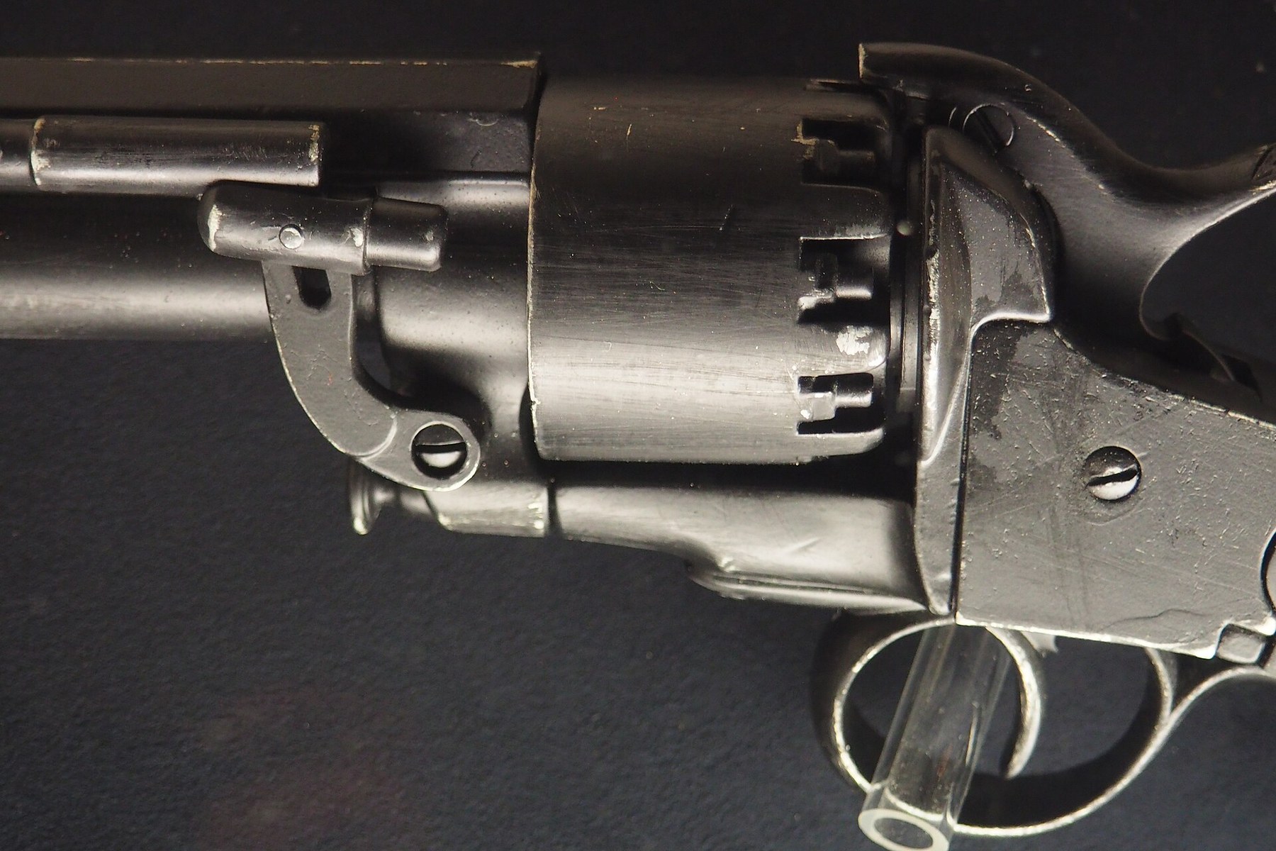
The cylinder has nine chambers bored around a central hole that fits over the shot barrel. Each chamber has a nipple screwed into the rear face, set in a recess. In the Musée de l’Armée photograph the recesses are separated by walls standing proud of the nipples — the usual percussion-revolver arrangement for shielding each cap from the flash of its neighbour and from cap fragments.
Holes in the rear face. Bodinson’s photograph of the reproduction’s cylinder notes “the holes between the nipples.”2 These are the sockets for the reciprocating cylinder-stop pin (§4.8). The 1859 hammer patent shows a further feature: notches into which the wings on the hammer head enter at the moment of firing, “for the purpose of holding the revolving cylinder fast.”11
Turning on the barrel. The 1869 patent says the cylinder “turns upon the central barrel M, on which it fits with a slight friction, and is provided with a circular recess … around the barrel, which will serve to hold the oil or other lubricator.”4 That is a description of the cartridge gun, but the bearing problem is the same on the percussion gun: the cylinder’s bore runs on the outside of the shot barrel, and fouling that gets between them makes the cylinder stiff to turn. Chapter 6 returns to it.
The ratchet. The cylinder is rotated by “a conventional hand,” Bodinson writes, acting on a ratchet at the rear of the cylinder.2 With nine chambers the ratchet has nine teeth, each of 40 degrees, against a six-shot’s 60.
4.5 The frame and the side plate
The LeMat’s frame is a solid frame below and behind the cylinder, open above it — there is no top strap; the rifled barrel’s rear lug sits over the front of the cylinder and is supported only through the shot barrel. Edmunds records that Huse called the frames cast iron, that they were in fact “malleable iron,” and that Girard claimed “cast steel.”12 Pietta’s catalogue gives a steel frame for the reproduction.13
The lockwork is reached through a side plate on the left of the frame (Pietta part 24, held by a side plate nut, 17).3 Julia’s Second Model serial 1475 has its serial number “stamped on the inside of the sideplate,” which confirms that the originals were built the same way.14 This is an important difference from the Colt, in which the lockwork is reached by removing the grip frame and trigger guard: the LeMat opens like a lock plate.
4.6 The lockwork: hammer, trigger, hand and mainspring
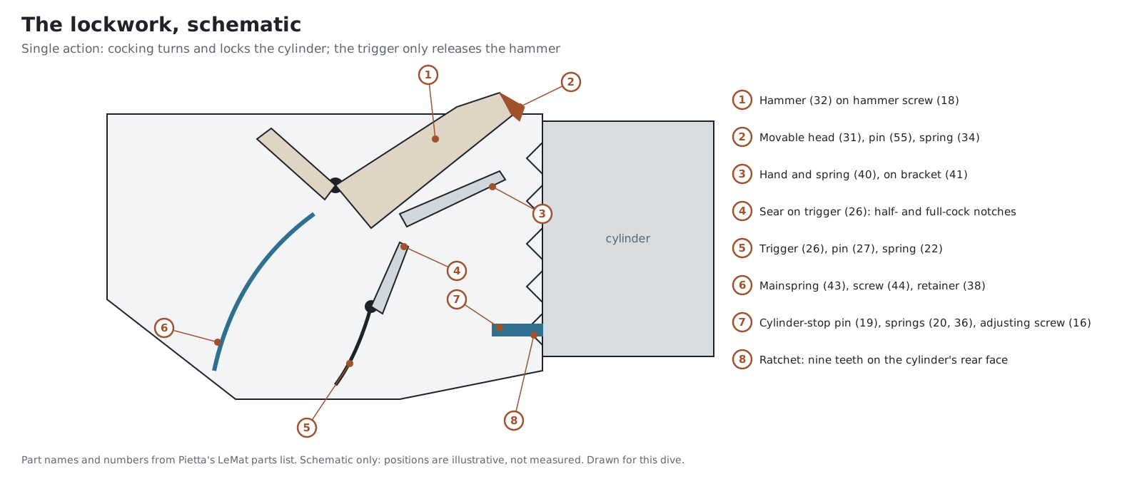
The LeMat’s lock is single action. Pulling the hammer back does all the work; the trigger only releases it. The parts are:
- Hammer (32), pivoting on the hammer screw (18), carrying the movable head (31) on its own pin (55), with a spring (34) and screws (33, 35) holding the head in either position. Rock Island describes the Second Model’s “center-mounted hammer pivot”; the Julia London gun has a “center mounted articulated hammer nose.”79
- Trigger (26) on its pin (27), with its spring (22). Its upper end forms the sear that engages notches in the hammer.
- Hand (40), with its own spring, mounted on a hand bracket (41) and screw (42) in Pietta’s design. The hand is pushed upward as the hammer is cocked and rotates the cylinder by its ratchet.
- Cylinder stop (19), with return spring (20), tension spring (36), retaining nut (21) and adjusting screw (16).
- Mainspring (43), held by its screw (44) and a retainer (38) with pin (39).
Half-cock and full-cock. The hammer has two working positions. At half-cock the cylinder is free to turn for loading and capping; at full-cock the gun is ready to fire. Edmunds describes loading this way: capping the nine chambers “requires half-cocking the gun and rotating the cylinder to it’s nine-stop capping locations, then full-cocking the gun and placing the last cap on the shotgun nipple.”12 Pietta’s general instructions warn never to pull the trigger at half-cock: “Attempting to pull the trigger in the half-cock position will strain the mechanism and possibly make it unsafe.”3
The reason the shot-barrel nipple is capped only at full cock is geometrical. The shot barrel’s nipple lies in a recess in the breech face directly under the hammer head, “at a slight distance back from the revolver cartridge-cylinder.”1 With the hammer down or at half-cock, the head sits in the way. At full cock the head is clear and the nipple can be reached.
No safety. Pietta’s manual is explicit: “LEMAT MODEL — For this model there are no safety devices or safety positions. ALWAYS carry this gun unloaded.”3 Unlike Colt and Remington percussion revolvers, which have safety notches or pins between the chambers, the LeMat has nothing on which the hammer can safely rest on a loaded cylinder.
4.7 The selector: the 1859 movable hammer head
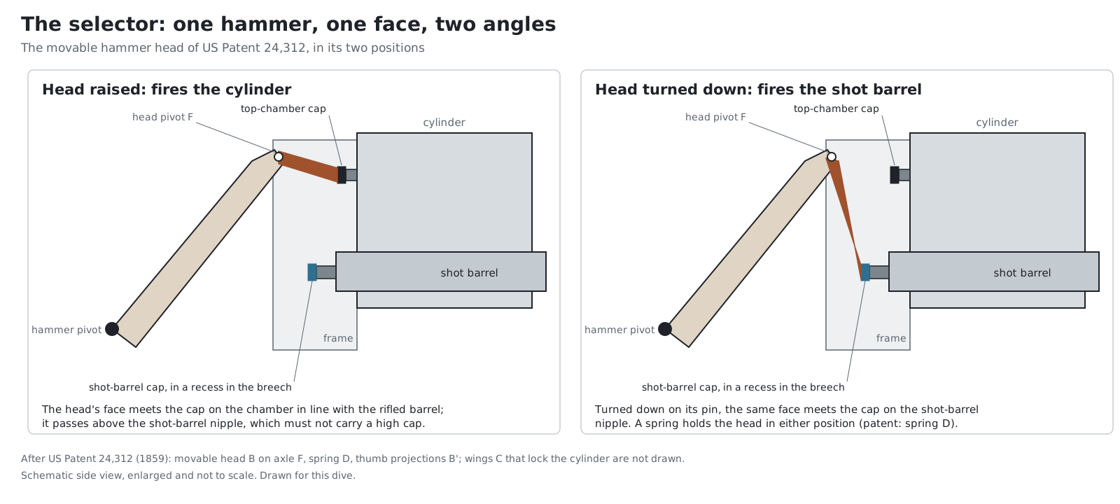
What the patent says. The selector is US Patent 24,312 of 7 June 1859. Its “movable head B … is required to fire of either the central barrel or the revolving chambers, at the will of the operator.” Lateral projections B′ give the thumb a purchase “in lowering or lifting up the movable head.” A spring D, fastened by a screw J, “serves for retaining the movable head in either of the positions required by the operator.”11 The claim describes a hinged head “so arranged that it shall present the same face in different directions for the purpose of discharging in succession different barrels.”11
In other words: one hammer, one striking face, two angles. Raised, the head strikes forward at the top chamber’s cap. Turned down about its pin, the same face is presented downward and forward at the shot-barrel nipple in the breech below.
How it looks on a gun. Bodinson describes the reproduction: “The hammer in revolver mode … rides over and clears the shotgun nipple. To fire the shotgun barrel, the nose of the hammer … is flipped down to align it with the nipple.”2 Julia’s First Model serial 28 has an “articulated hammer nose with small ears on each side for positioning to fire the smoothbore bbl” — the patent’s thumb projections.6 The Rock Island pinfire gun’s hammer has “a vertical selector switch.”15 Pietta’s catalogue distinguishes a “cross pin barrel selector” on its Cavalry and Army patterns from a “spur barrel selector” on its Navy.13
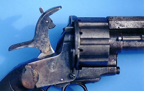
The two-hammer cock it replaced. The 1856 patent’s preferred mechanism was a cock with two separate hammers, the second locked in place by a spring-loaded ring that had to be pushed down with the trigger finger while the other hand set the hammer.1 The 1859 head does the same job with one part, one spring and a thumb. It is a good example of a mechanism improving between patent and production, and it is one reason the gun is so often credited to the wrong patent (Volume 1).
Which way is “up.” The default position is the revolver position, and the shot barrel is selected deliberately. Nothing in the sources describes an interlock to stop the shooter firing the shot barrel with the head turned down and the cylinder still loaded, and there is no need for one: firing the shot barrel does not fire the cylinder. But the reverse error — forgetting to return the head to the revolver position after firing the shot barrel — means the next pull of the trigger falls on an empty, fired nipple and nothing happens. The 1856 patent warns of exactly this for its own mechanism: “If there be any bullet-charges still left, the cock is again brought to its regular form.”1
Pietta’s double-percussion warning. Pietta’s manual contains a warning about the shot-barrel cap that bears directly on the selector:
“After loading the cylinder and the center barrel, NEVER place any cap on the nipple under the hammer, for the .20 ga. The cap could be misplaced (too high) causing a double percussion which would fire 2 shots simultaneously.”3
Read literally, this forbids ever capping the shot barrel, which cannot be what is meant, since the barrel cannot otherwise be fired. The mechanism suggests what the hazard is: a cap seated high on the shot-barrel nipple can be struck by the hammer head even in the revolver position, so that one fall of the hammer fires both the top chamber and the shot barrel. The plausible reading is “do not leave a cap on the shot-barrel nipple except when you intend to fire it, and seat it fully.” Volume 5 discusses it with the loading sequence. The manual’s own words are quoted here, and the interpretation is this work’s.
4.8 Holding the chamber in line: pin, bolt and hammer wings
A revolver must stop its cylinder with a chamber exactly in line with the bore and hold it there while the hammer falls. The LeMat has three mechanisms associated with this, and they are worth separating.
1. The reciprocating cylinder-stop pin. The early guns, and the Pietta reproduction, lock the cylinder with a pin that moves in and out of the standing breech and enters holes drilled in the rear face of the cylinder between the nipples. Bodinson: “A small pin moves in and out of the face of the standing breech as the gun is cocked to mate with holes drilled into the rear of the cylinder.”2 Garbers calls it “the pin-type cylinder lock, an extremely complicated and expensive system,” and adds: “Reports claim combat grit filled the pin holes and caused the cylinder to either over- or under-rotate.”5 The Baby LeMats use it too: “the earlier style reciprocating pin system to rotate and lock cylinder seen in standard models that were used early in the Civil War.”16
2. A conventional bolt, on later guns. Bodinson: “Historically, the pin system was later replaced by a more conventional and more rugged locking lug.”2 Garbers likewise says the pin lock was “changed in later production revolvers.”5 Neither identifies the serial range at which the change was made, and no catalogue description consulted describes the later lock in detail. One carbine, Julia’s serial 3157, has yet another arrangement: “a pin detent cylinder stop that makes contact with dimples on front of cylinder,” tensioned by a flat spring.17
3. The hammer wings. The 1859 patent’s second claim is “small lateral wings for locking the revolving chambers in position.”11 These are on the hammer head itself and enter notches in the cylinder as the hammer falls, so that whatever the cylinder stop has done, the cylinder is held “fast” at the moment of ignition. It is a belt-and-braces arrangement, and an ingenious one: it locks the cylinder at the one moment when locking matters most, and it does it with the part that is already moving there.
What goes wrong. Edmunds’s experience with a Navy Arms reproduction, shooting modern non-corrosive black powder, was that “after an average of four or five shots, the cylinder had to be hand-turned to index the next chamber to line up with the bore,” because “the reciprocating locking pins in the frame did not operate freely enough to engage their bored-out recesses in the cylinder.”12 Bodinson’s assessment of the same system on a Pietta is milder: it “works fine as long as the pin and its corresponding holes are kept clean.”2 Pietta provides an adjusting screw for the stop’s timing: “Screwing this screw will slow down the release of the cylinder stop stud, unscrewing it will put forward the release of the cylinder stop stud.”3
4.9 The cycle of operation, step by step
For the percussion gun, loaded and capped, revolver position selected:
- Hammer down. The hammer head rests against the cap on the top chamber. With no safety position, this is the condition Pietta’s manual forbids for carry (Volume 5).3
- Cocking begins. The hammer rotates rearward on its screw against the mainspring. The trigger’s sear rides on the hammer’s cam surface.
- The cylinder unlocks. The cylinder-stop pin is withdrawn from its hole in the rear of the cylinder, and the hammer’s wings come out of their notches.
- The hand rotates the cylinder. The hand, rising with the hammer, pushes on the next tooth of the ratchet and turns the cylinder 40 degrees.
- The half-cock notch passes. At half-cock the sear catches a notch; continuing past it, the cylinder keeps turning.
- The cylinder locks. The stop pin re-enters the next hole as the new chamber comes into line, timed by the adjusting screw.
- Full cock. The sear drops into the full-cock notch. The hammer is held against the mainspring.
- Trigger. Pressing the trigger lifts the sear out of the notch. The mainspring drives the hammer forward.
- Lock and fire. As the hammer arrives, its wings enter the cylinder notches and hold the cylinder; the head crushes the cap; the cap’s flash passes through the nipple and fires the chamber.
- To fire the shot barrel: cock the hammer, turn the head down with the thumb, cap the shot-barrel nipple at full cock, and press the trigger. The head strikes the central cap. Return the head to the revolver position before firing the cylinder again.
Steps 3, 6 and 9 rest on the patent and on the descriptions of the pin system; the exact order in which the pin withdraws and the hand begins to push on an original gun was not found described and is set out here as the logic of the parts.
4.10 The loading lever and the shot-barrel rammer
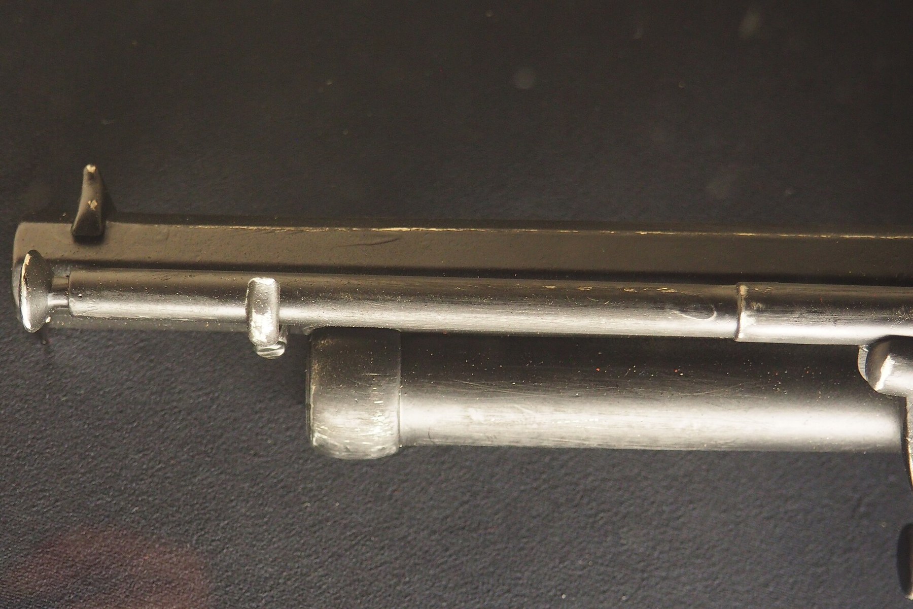
The loading lever is a jointed rammer under the rifled barrel. Its plunger (Pietta 5) seats a ball in the chamber below the barrel. On the First Model it is on the right side; on the Second Model, the London guns and most reproductions it is on the left.789
The lever is also a tube. The shot barrel cannot be loaded with the cylinder lever; its rammer is a separate short rod carried inside the lever’s hollow handle (Pietta 1, the “shot barrel ramrod,” inside 2, the “loading lever tube”).3 Largen notes that LeMat originally intended a sliding rammer for the cylinder and a jointed one for the shot barrel, but that “a jointed rammer was employed for both duties,” with “a removable ramrod for use in charging the shot barrel … inserted in the rammer’s lever.”18
Why it broke. A hollow lever is weaker than a solid one. Bodinson, on the Pietta: “Because the handle of the lever is hollow and contains the ramrod for the shotgun barrel, it’s not as strong and tough as a conventional cap-and-ball loading lever. The shotgun ramrod should always be in position inside the hollow handle to reinforce it when the lever is being used to seat a ball.”2 Edmunds records what happens when the rod is not replaced: Hayes Otoupalik and Doug Adams, loading reproductions, used a wooden rod for the shot barrel and then seated balls with the lever, and “in each case, the loading levers broke off or badly bent the tube section, rendering it useless.”12 Otoupalik’s conclusion: the inner rod was “too short and impractical to use,” so it was left out, which weakened the lever, which then bent.12
This is the most likely explanation of the large number of originals found without their levers (Volume 2): the lever and the rammer were one assembly, the rammer was useless and was discarded, and the lever without it failed.
The retaining catch. The lever is held up by a spring catch (Pietta 50, 51). College Hill notes that on originals “the loading lever retaining catch spring … is subject to breakage from normal use … almost every surviving LeMat has had this part replaced.”8 Bodinson adds that on the reproduction, “when shooting the shotgun barrel, the loading lever will consistently flip up and out of its spring clip and leave the shotgun ramrod on the ground at your feet.”2
Pull-out assembly latch. Rock Island lists a “pull-out assembly latch” among Second Model features.7 This is the barrel latch (§4.3), not the lever catch.
4.11 Sights
The rear sight is a groove in the top of the hammer, visible only at full cock; the front sight is a tall post dovetailed into the barrel near the muzzle. Bodinson calls the reproduction’s sights “period crude”: “The rear sight is a groove along the top of the hammer while the windage adjustable front sight is a large, thick pyramidal post — good for combat, bad for target shooting.”2 Julia’s London guns have “the tall LeMat front sight”; College Hill notes that the original front sight carried a “barley corn” top “often broken and missing.”98 The front sight is drifted in its dovetail for windage; there is no elevation adjustment except by filing.
4.12 The cartridge guns: what changed
The 1869 patent and the catalogues describe the cartridge LeMats as the percussion gun with four changes:4719
- A loading gate on the right of the frame for the cylinder — “a side-swinging loading gate” on the pinfire gun, and “on the upper right” on the centerfire.
- An ejector rod on the right of the frame, replacing the loading lever.
- A hinged breech for the centre barrel on the centerfire gun, swinging laterally, carrying the barrel’s firing pin, and driving a half-cylinder extractor when opened. On the pinfire gun the centre barrel stays a percussion muzzleloader.
- A double hammer on the centerfire gun: a fixed striker for the cylinder and a hinged auxiliary hammer for the centre barrel’s pin — a return, in a different form, to the two-hammer idea of 1856.
4.13 Design judgements: what worked and what did not
What worked.
- Capacity. Nine shots plus one in a single hand, against five or six. The New Orleans board’s sentence about pouring “10 shots into their very faces” is the whole marketing case, and it is true.2
- The selector. One movable head, one spring, thumb operation. No source reports the selector itself as a common failure, though the hammer nose is listed among parts often repaired or replaced on originals.8
- The hammer wings. Locking the cylinder with the falling hammer is elegant.
What did not.
- The loading lever. A hollow lever that only works with a rammer nobody used. The evidence of the surviving guns is decisive.
- The pin cylinder lock. Effective when clean; fouled quickly; replaced on later production.
- Weight and bulk. The cylinder diameter is set by the shot barrel and nine chambers; nothing can be done about it within the design.
- Calibre. A .42 bore in an army whose revolvers were .36 and .44 is a supply problem, not a mechanical one, but it was decisive in service (Volume 2).
Edmunds’s verdict on the whole: “Nothing about the LeMat was easy, but when properly loaded, it was a great weapon, nevertheless!” — in the words of his correspondent Otoupalik.12
4.14 What could not be verified
- The serial range at which the reciprocating pin gave way to a conventional bolt, and the form of the later lock.
- The exact sequence of pin withdrawal and hand engagement in an original lock; §4.9 sets out the logic of the parts.
- Whether the cylinder-locking notches for the hammer wings are present on the Pietta reproduction as on the patent drawing.
- Any original armourer’s manual or factory parts list. Pietta’s list is used for names.
- What Pietta’s double-percussion warning means exactly. The manual is quoted; the reading offered is this work’s.
Sources
Footnotes
-
A. Le Mat, US Patent 15,925, “Improved Fire-Arm,” 21 October 1856, read 2026-10-18. ↩ ↩2 ↩3 ↩4 ↩5
-
Holt Bodinson, “The Awesome LeMat,” GUNS Magazine, 7 February 2014, read 2026-10-18. ↩ ↩2 ↩3 ↩4 ↩5 ↩6 ↩7 ↩8 ↩9 ↩10 ↩11
-
F.lli Pietta, instruction manual for muzzleloading percussion firearms, English edition (file “avancarica_Ing.pdf”), pp. 15 (LeMat safety), 20–22 (loading; “About the Le Mat revolver”), 26–28 (handling), 30 (LeMat cleaning), 50–51 (LeMat parts list), https://pietta.it/wp-content/uploads/2024/05/avancarica_Ing.pdf, read 2026-10-18. ↩ ↩2 ↩3 ↩4 ↩5 ↩6 ↩7 ↩8 ↩9 ↩10 ↩11 ↩12 ↩13
-
F. A. Le Mat, US Patent 97,780, 14 December 1869, read 2026-10-18. ↩ ↩2 ↩3 ↩4
-
Alan Garbers, “The LeMat’s Grapeshot Revolver,” GUNS Magazine, 15 September 2021, read 2026-10-18. ↩ ↩2 ↩3 ↩4 ↩5
-
James D. Julia, Inc., lot 148, First Model serial 28, read 2026-10-18. ↩ ↩2 ↩3
-
Joe Engesser, “The LeMat Revolver,” Rock Island Auction Company, read 2026-10-18. ↩ ↩2 ↩3 ↩4 ↩5
-
College Hill Arsenal, Second Model serial 1784, read 2026-10-18. ↩ ↩2 ↩3 ↩4 ↩5
-
James D. Julia, Inc., London LeMat serial 8074, read 2026-10-18. ↩ ↩2 ↩3 ↩4
-
James D. Julia, Inc., pinfire LeMat serial 3023, read 2026-10-18. ↩
-
A. Le Mat, US Patent 24,312, “Adjustable Hammer for Revolving Firearms,” 7 June 1859, read 2026-10-18. ↩ ↩2 ↩3 ↩4
-
Frederick R. Edmunds, “Some Thoughts on the Confederate LeMat Revolver,” ASAC Bulletin 100:24–28 (2009), read 2026-10-18. ↩ ↩2 ↩3 ↩4 ↩5 ↩6
-
F.lli Pietta, revolver catalogue (“Catalog 2025,” file dated 2026), pp. 43–47, read 2026-10-18. ↩ ↩2
-
James D. Julia, Inc., Second Model serial 1475, read 2026-10-18. ↩
-
Rock Island Auction Company, auction 80, lot 249, Belgian LeMat pinfire, read 2026-10-18. ↩
-
James D. Julia, Inc., lot 1442, Baby LeMat serial 5, read 2026-10-18. ↩
-
James D. Julia, Inc., lot 137, pinfire carbine serial 3157, read 2026-10-18. ↩
-
Floyd Largen, “Weaponry: Le Mat,” Military History, October 1996, via HistoryNet, read 2026-10-18. ↩
-
Rock Island Auction Company, auction 64, lot 265, cased pinfire LeMat, read 2026-10-18. ↩
Comments (0)