H&K Mk 23 · Volume 3
How It Works: A Linkless Browning with a Buffered Guide Rod
The Mk 23's cycle of operation part by part, from H&K's own manual, set beside the 1991 patent whose number is moulded into the frame: the cam on the guide rod, the two-spring recoil assembly, the barrel O-ring, the DA/SA fire control and the separate decocker
3.1 What this volume rests on
Two documents carry almost everything here. The first is Heckler & Koch Inc.’s operator’s manual for the commercial Mark 23, revised March 2007, which has a principle-of-operation section, a step-by-step cycle of operation, a description of each safety and an exploded parts list with H&K part numbers.1 The second is US Patent 5,309,815, “Firearm, particularly handgun”, filed by Heckler und Koch GmbH with a German priority date of 25 March 1991, which describes a recoil system with the same parts as the manual’s list.2
H&K’s illustrations in the manual are its copyright and are not reproduced. The diagrams in this volume are either the patent’s own drawings, which are public domain as US government works, or drawn for this dive from the manual’s text and parts list. Where a drawing has had to assume something the sources do not say, its caption says so.
The manual describes the commercial Mark 23. H&K says the commercial pistol is “almost identical to the MK 23, MOD 0 … right down to its threaded barrel”, the main differences being the slide markings and a barrel made to SAAMI headspace specifications.1 What follows therefore applies to both, with that caveat; the differences that can be seen from outside are in Volume 4.
3.2 The pistol in numbers
H&K’s manual gives these specifications. Several of them were changed on H&K’s later web pages, and the later figures are set beside them in the last section of this volume rather than mixed in here.
Table 1 — The pistol in numbers
| Item | Figure in H&K’s 2007 manual |
|---|---|
| Calibre | .45 ACP, “up to and including the commercial +P cartridges” |
| Operating principle | Short recoil, semi-automatic |
| Action type | ”Modified Browning type, linkless” |
| Overall length | 9.65 in (245 mm) |
| Barrel length | 5.87 in (149 mm) |
| Sight radius | 7.76 in (197 mm) |
| Twist | 378 mm (14.88 in) |
| Height without magazine | 5.90 in (150 mm) |
| Frame width | 1.58 in (38.8 mm) |
| Weight with empty 12-round magazine | 2.66 lb (1.21 kg) |
| Empty magazine, 12-round / 10-round | 0.81 lb (366 g) / 0.72 lb (327 g) |
| Force to retract the slide | 8.5 kg (18.74 lb) |
| Trigger pull, single action / double action | 4.85 lb (2.20 kg) / 12.13 lb (5.50 kg) |
| Capacity | 10 or 12 rounds |
Source: H&K manual, Section 2.1
The slide force is worth noticing. At 8.5 kg (18.7 lb), it is the force H&K gives to start the slide back by hand, and it is the first thing a new shooter notices: the recoil assembly is stiff. Why it is stiff is the subject of most of this volume.
3.3 The major groups
The manual divides the pistol into six groups, and the field strip in Volume 5 takes it down to exactly these:1
- Slide. Houses the firing pin, the firing pin block and the extractor, and cocks the hammer during recoil. H&K’s feature list calls it a “one-piece machined steel slide”.
- Captured recoil/buffer spring assembly, with guide rod. “Absorbs recoil and returns the slide and barrel to their forward positions; reduces impact of slide on receiver during recoil. The recoil spring is ‘captured’ by a C-clip on the end of the guide rod.”
- Threaded barrel, with locking block. The locking block “initiates locking and unlocking of the breech”, and “the O-ring holds the barrel tight in the slide until unlocking.”
- Frame. A one-piece fibreglass-reinforced polymer moulding with two metal inserts, the “locking insert” and the “guiding part”, cast in. The slide rides on the inserts.
- Magazine. Sheet steel, double-column, 12 rounds (or 10).
- Slide release. The slide stop, which is also the disassembly pin.
3.4 The Browning inheritance, and what H&K changed
The Mk 23 is a short-recoil pistol of the family John Browning founded: barrel and slide are locked together when the cartridge fires, recoil together a short way while the bullet leaves the barrel and the pressure falls, and then the barrel is tilted down out of engagement so the slide can go on alone. The hub’s SIG P320 / M17 dive, Volume 6 gives the general account of the tilting-barrel cycle and the spring that governs it; this volume concentrates on what is particular to the Mk 23.
Browning’s own pistols tilted the barrel in one of two ways. The M1911 hangs the breech end of the barrel on a swinging link pinned to the frame; the link pulls the breech down as the barrel moves back. The later Browning-designed High Power replaced the link with a fixed cam: a lug under the barrel rides against a slotted cam surface in the frame. H&K’s patent illustrates both as prior art, as a “known Colt-Browning system with cam curve and control bolt” and a “further known system having a barrel chain control”.2
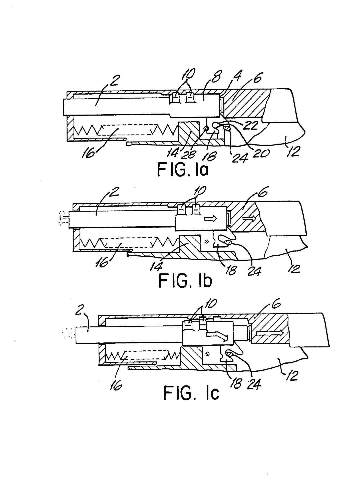
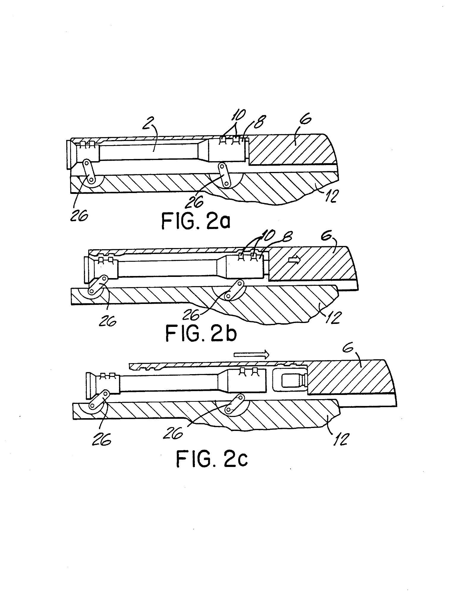
H&K’s manual calls the Mk 23’s action a “modified linkless Browning-style short recoil system”.1 It is linkless in the High Power’s sense, a cam rather than a link. What is modified is where the cam lives. In the High Power the cam surface is part of the frame. In the Mk 23, by the manual’s own description, the barrel is tilted by “the engagement of the angled surfaces of the locking block with those located in the recoil spring guide rod”.1 The cam is on the rear of the guide rod. And the guide rod is not fixed: it can move backwards a short distance against a spring of its own. That is the whole idea of the design, and it is what the patent claims.
The second modification is the locking surface. A 1911 locks by lugs on top of the barrel engaging recesses in the slide’s roof. The Mk 23 locks by a single squared-off block at the breech end of the barrel engaging the ejection port: the slide “is locked to the barrel by the engagement of the barrel locking block within the ejection port milled into the slide”.1 VISIER’s history of the USP describes the same lock in both pistols as “a square block à la Petter in the ejection window”, after Charles Petter’s designs, and says the makers call the whole arrangement a “buffer Browning lock”.3 There are no barrel lugs to machine and no matching recesses in the slide.
3.5 The patent on the frame
Volume 1 set out the circumstantial case that US Patent 5,309,815 describes the Mk 23’s recoil system: the patent’s German priority date of 25 March 1991 precedes the OHWS development contracts, and its parts match the manual’s parts list. There is more direct evidence than that.
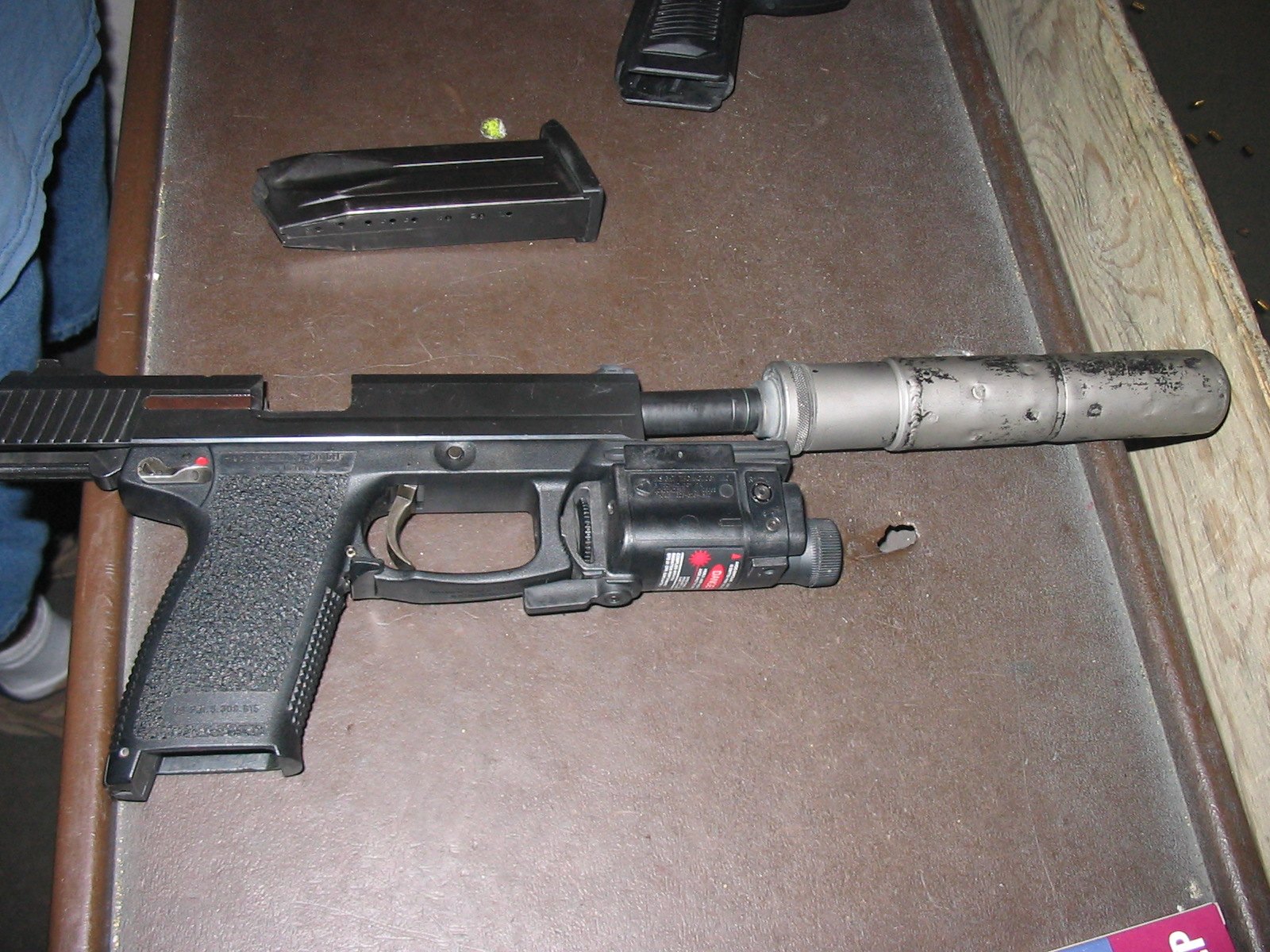
On the right side of the commercial Mark 23’s frame, below the grip panel’s stippling near the magazine well, is a small moulded panel of text. In the Commons photograph of a commercial pistol reproduced in this volume, the panel reads, as far as the photograph’s resolution allows, as a US patent marking ending in 5 309 815.
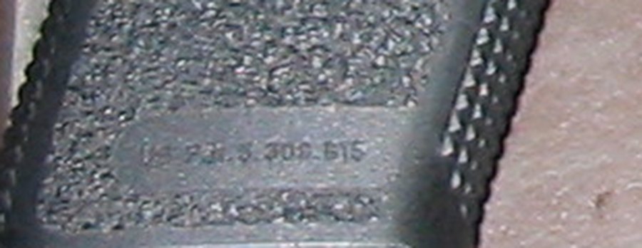
The reading is limited by the photograph, which is a 1,600-pixel snapshot taken at a range bench, and the first characters cannot be made out. The digits that can be read match the patent. Taken with the matching parts list, that makes US 5,309,815 the best-supported identification of what H&K’s literature calls the “Patented HK recoil reduction system”.4 It is still an identification made for this dive, not a statement by H&K; a sharper photograph of the panel would settle it, and one is listed as owed in this dive’s README.
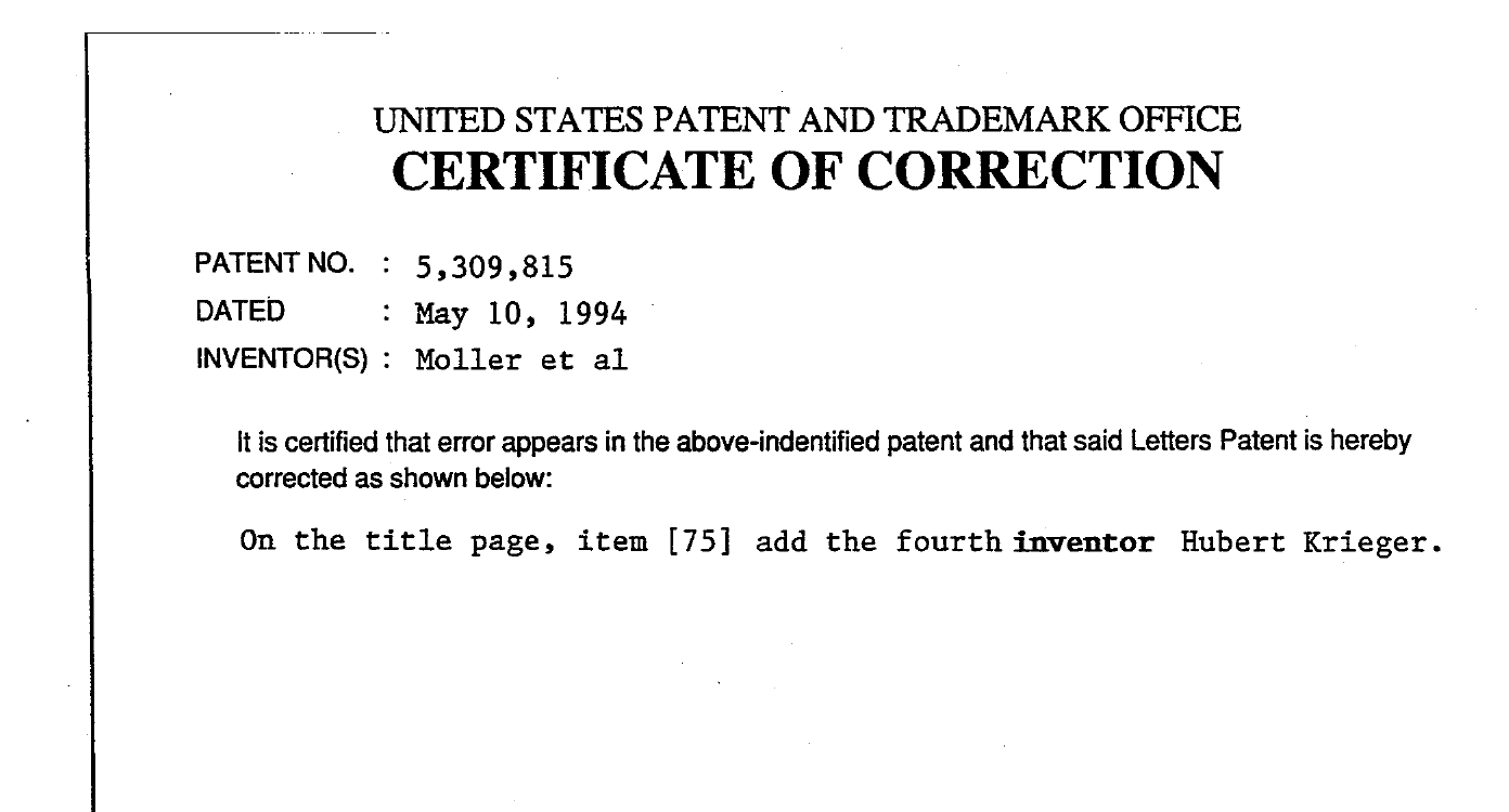
The patent was issued on 10 May 1994 to Tilo Möller, Rudolf Brandl and Helmut Weldle. A certificate of correction issued on 28 February 1995 added a fourth inventor, Hubert Krieger, who is missing from the front page and therefore from most citations of the patent.2
Two later H&K patents deal with recoil attenuation in handguns: US 5,581,046, by Helmut Weldle and Hermann Albrecht, with a German priority date of 2 December 1993, which uses an “absorber spring” to pre-stress a movable barrel assembly.5 It postdates the OHWS development work, is not marked on the Mark 23 in any photograph found, and is not discussed further here.
3.6 The cycle, step by step
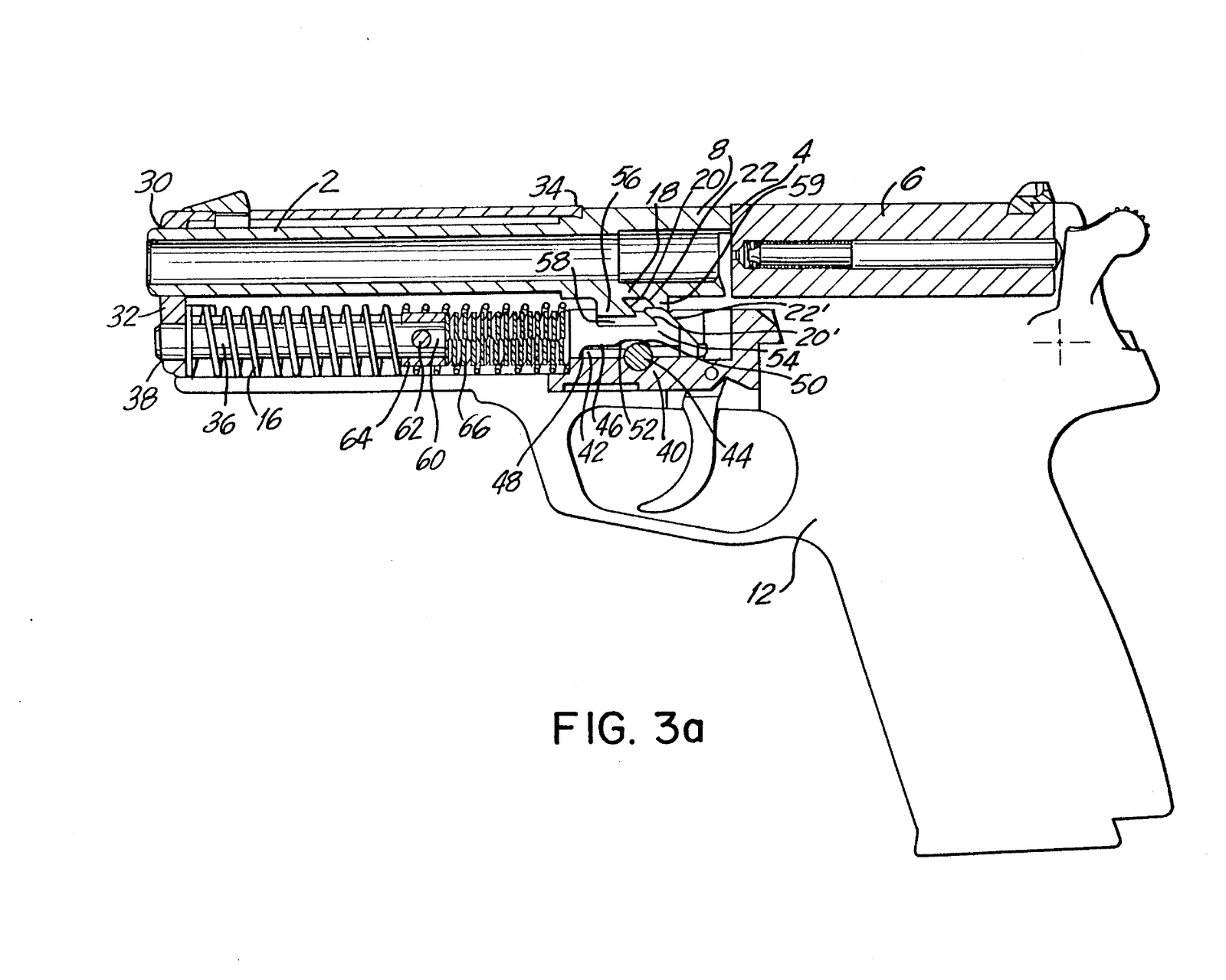
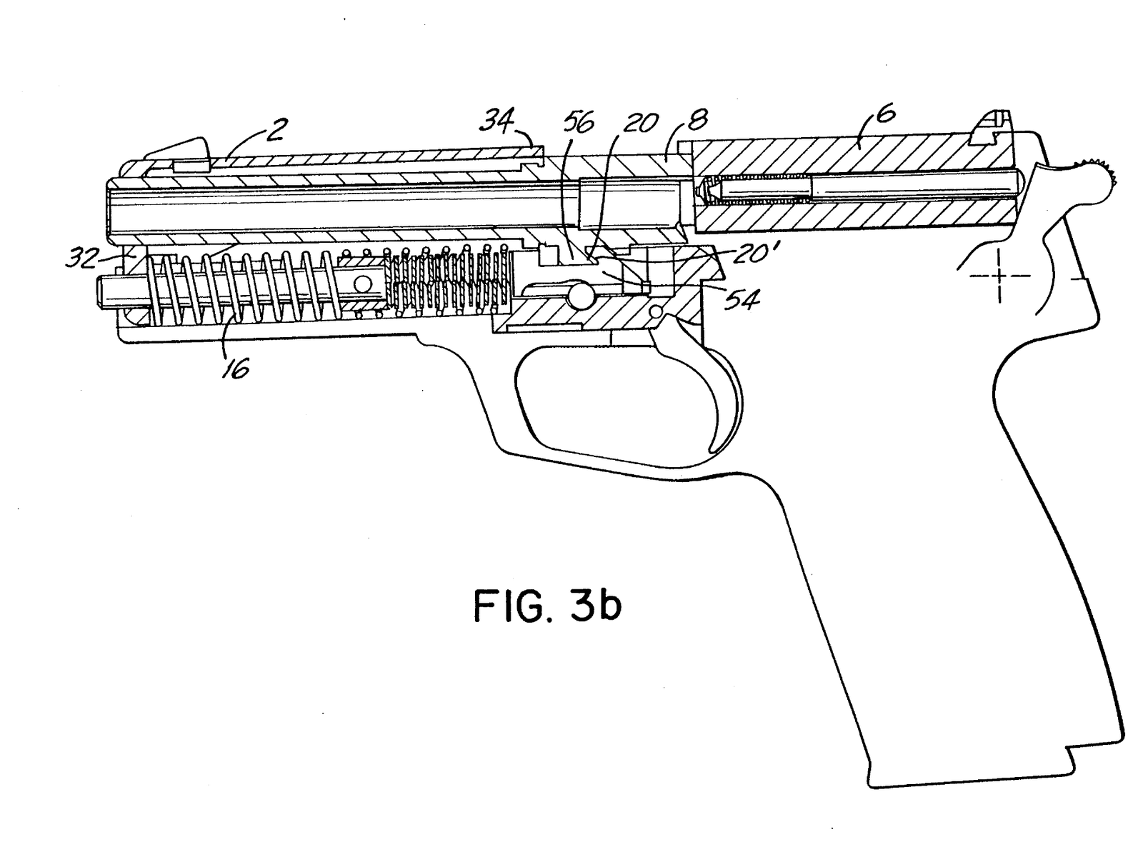
H&K’s manual gives an eight-step cycle of operation. The patent gives the same sequence in five drawings, Figures 3a to 3e, in more detail. They are set side by side here, the manual’s step first and the patent’s account after it. The patent’s drawing is of an embodiment, not a production drawing, and its proportions are not the Mk 23’s.
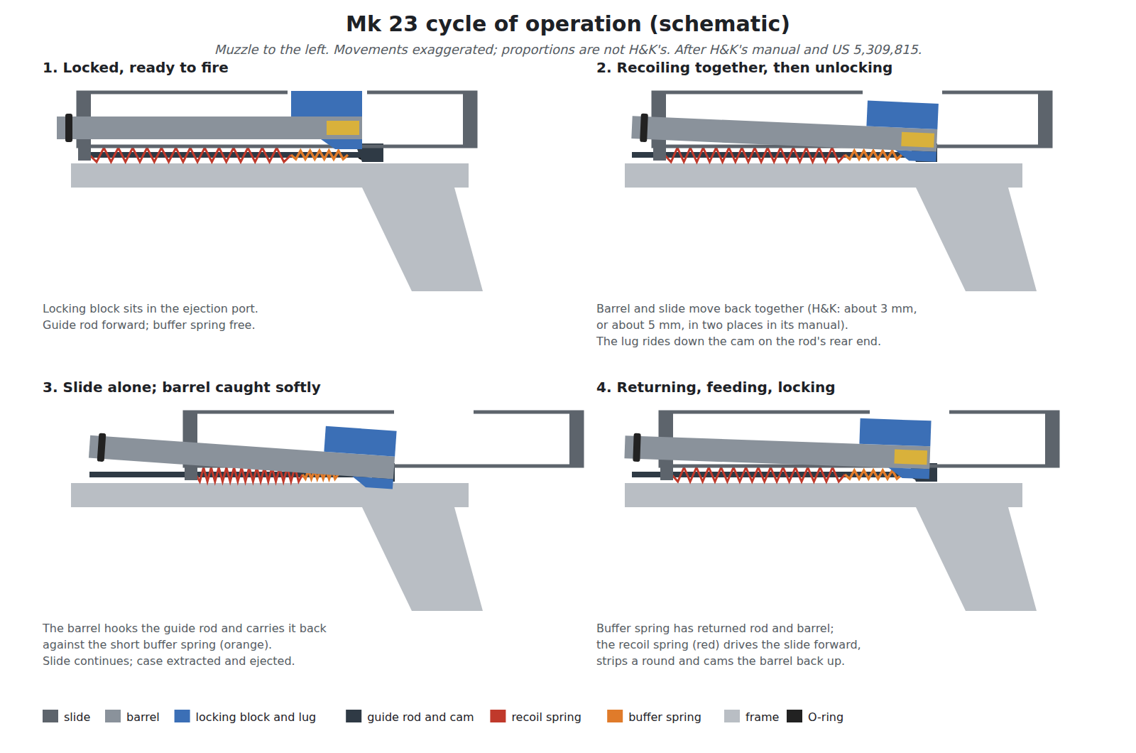
1. Firing. “Pulling the trigger rearward pulls the trigger bar forward. The trigger bar pivots the sear actuator upward which disengages the firing pin block. At the same moment, the sear is pivoted out of engagement from the lower of the two shelves located on the hammer.” The hammer spring drives the hammer onto the firing pin.1 The fire control is described later in this volume.
2. Unlocking. The slide and barrel are driven back together, locked by the barrel’s block in the ejection port. The opposing angled surfaces on the locking block and the guide rod “cause the rear of the barrel to tilt downward as the slide moves rearward”, and the block leaves the ejection port.1
In the patent’s terms (Figure 3b), the “unlocking bevel” on a half-dovetail extension under the barrel slides down a complementary bevel on the “barrel stop” at the rear of the guide rod, and the extension comes to rest in the barrel stop. “The tilting movement which the barrel 2 has carried out in this phase is sufficient to loosen the engagement … between the rear barrel section 8 and the breechblock 6.”2
How far barrel and slide travel together before they part is given twice in H&K’s manual, and differently. Section 3 says that “after approximately 3mm, the locking block will stop the rearward movement of the barrel”; the cycle-of-operation section says that “by the time the slide and barrel have recoiled approximately 5mm, the projectile has left the barrel … The barrel locking block then disengages from the slide.”1 The two may describe different moments (the barrel arriving at its stop, and the block clearing the slide), but the manual does not say so, and both figures are given here as printed.
3. The barrel is caught softly. This is the step the manual compresses into one phrase and the patent spends most of its description on. In an ordinary Browning pistol the barrel, once unlocked, stops dead against the frame or link. In the patent, the barrel is now hooked to the guide rod and carries it rearward “against the action of the buffer spring 66”. The guide rod slides back by the length of an elongated recess in its rear end, which rides on a transverse pin in the frame, until the front end stop of that recess meets the pin. “In this phase, the buffered barrel stop 54 softly takes up the barrel attachment 18.” Barrel and guide rod come to rest; the slide goes on.2
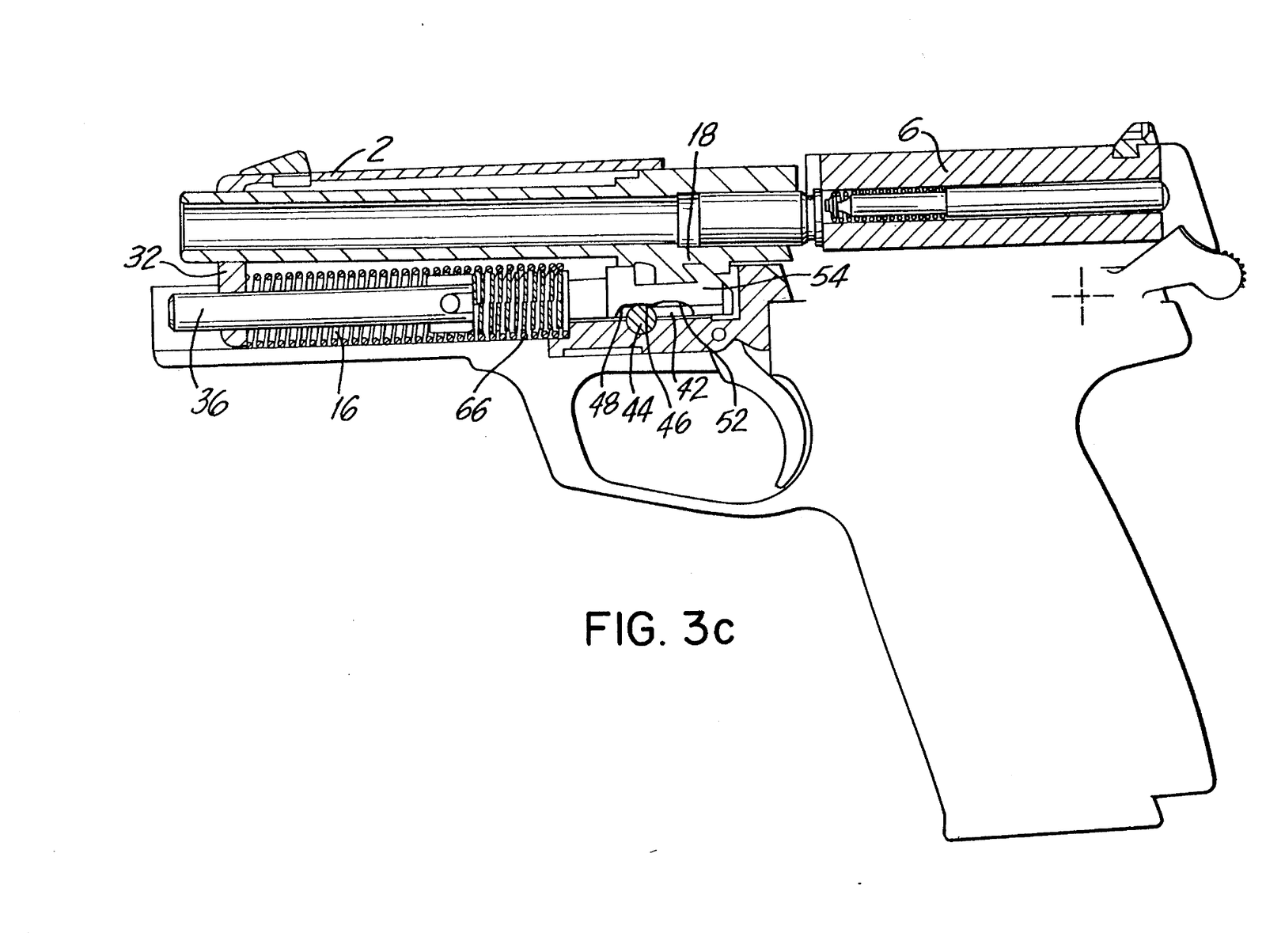
4. Extraction and ejection. “The empty cartridge case is held firmly against the face of the slide by the claw of the extractor as the slide recoils rearward. … The rim of the cartridge case strikes the stationary ejector.” The ejector is in the frame, on the left of the magazine well.1
5. The barrel is pushed back to its position. In the patent, the compressed buffer spring now pushes the guide rod, and with it the barrel, forward again, back to the position set by the stud bolt bearing against the front of its slot (Figure 3d). By the time the slide reaches the end of its travel, the barrel is already home.2
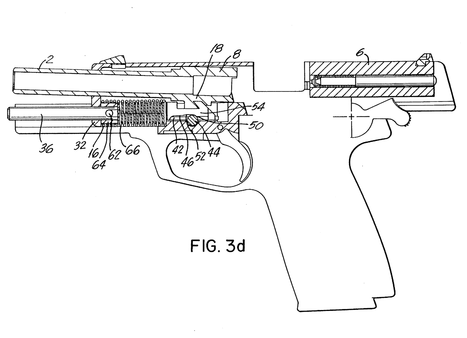
6. Cocking and the slide’s buffered stop. “As the slide continues rearward the recoil impulse is dampened by the buffer spring. The recoil spring is compressed and the hammer recocked.”1 In the patent the slide’s front end meets a bushing on the guide rod and drives it back against the buffer spring, so the slide is stopped by the buffer spring and the main recoil spring together rather than by a metal-to-metal impact on the frame (Figure 3e). The patent adds that in practice the full buffer travel “is preferably not moved over completely”: the slide’s remaining momentum is “taken up softly from beginning to end” by the springs and the bushing’s mass.2
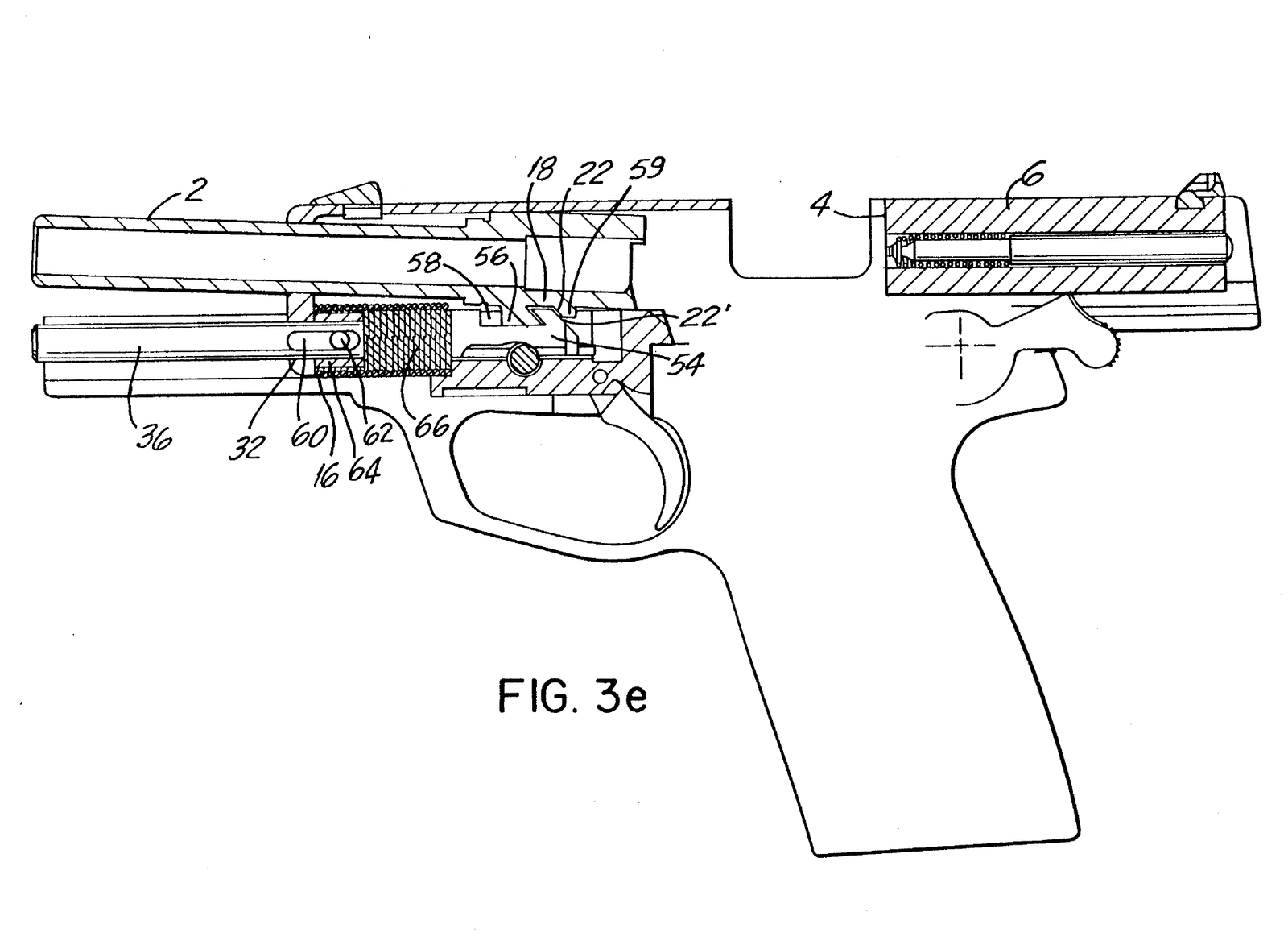
So the one buffer spring does two jobs, and the patent says so: it “first of all gently intercepts the barrel … then moves it again forward … and thereupon also softly intercepts the breechblock”.2 It is, in the patent’s words, “a joint buffer device” for both.
7. Feeding and chambering. “The compressed recoil spring drives the slide forward.” If the magazine is empty, the follower lifts the slide release and the slide locks open. Otherwise the slide face picks up the top round, the magazine lips guide the bullet’s tip into the chamber, and “the claw of the extractor snaps onto the rim of the cartridge case as it becomes parallel with the bore”. The slide drives the round forward “until the projectile enters the mouth of the forcing cone of the bore and the face of the slide contacts the rear of the barrel locking block.”1
8. Locking. “The slide presses the barrel forward. As it does, the opposing angled surfaces of the barrel locking block and recoil spring guide rod pivot the rear end of the barrel up into engagement with the ejection port in the slide.”1 The patent adds a point the manual does not make. In the locked position a pyramidal-frustum-shaped extension of the barrel attachment is “seated snugly” on the barrel stop, and “assurance is thus had that the barrel 2 always assumes the same position relative to the sighting device seated on the breechblock”.2 A barrel that returns to the same place against the sights every time is a precondition of the accuracy H&K claimed, which is examined in Volume 6.
3.7 The recoil assembly: two springs on one rod
H&K’s parts list, item by item, describes the recoil assembly exactly. The numbers in the first column are the manual’s key numbers; the part numbers are H&K’s.1
Table 2 — The recoil assembly: two springs on one rod
| Key | Part | H&K part no. | What it does (analysis from the manual and patent) |
|---|---|---|---|
| 15 | Guide rod | 215724 | Carries both springs; its rear end is the cam (the patent’s “barrel stop”) |
| 16 | Recoil spring retainer | 215725 | Rear seat of the recoil spring; sits “on the shelf on the front of the barrel locking block” in reassembly |
| 17 | Buffer spring | 215726 | The short, stiff inner spring |
| 18 | Dual roll pin (buffer spring retainer) | 986433 | Cross pin through the rod; the patent’s stud bolt |
| 19 | Buffer spring retainer | 215727 | The patent’s bushing |
| 20 | Spring ring | 929191 | The “C-clip” that captures the assembly |
| 21 | Washer | 215728 | Front washer under the clip |
| 22 | Recoil spring | 215729 | The main spring, outside the buffer spring |
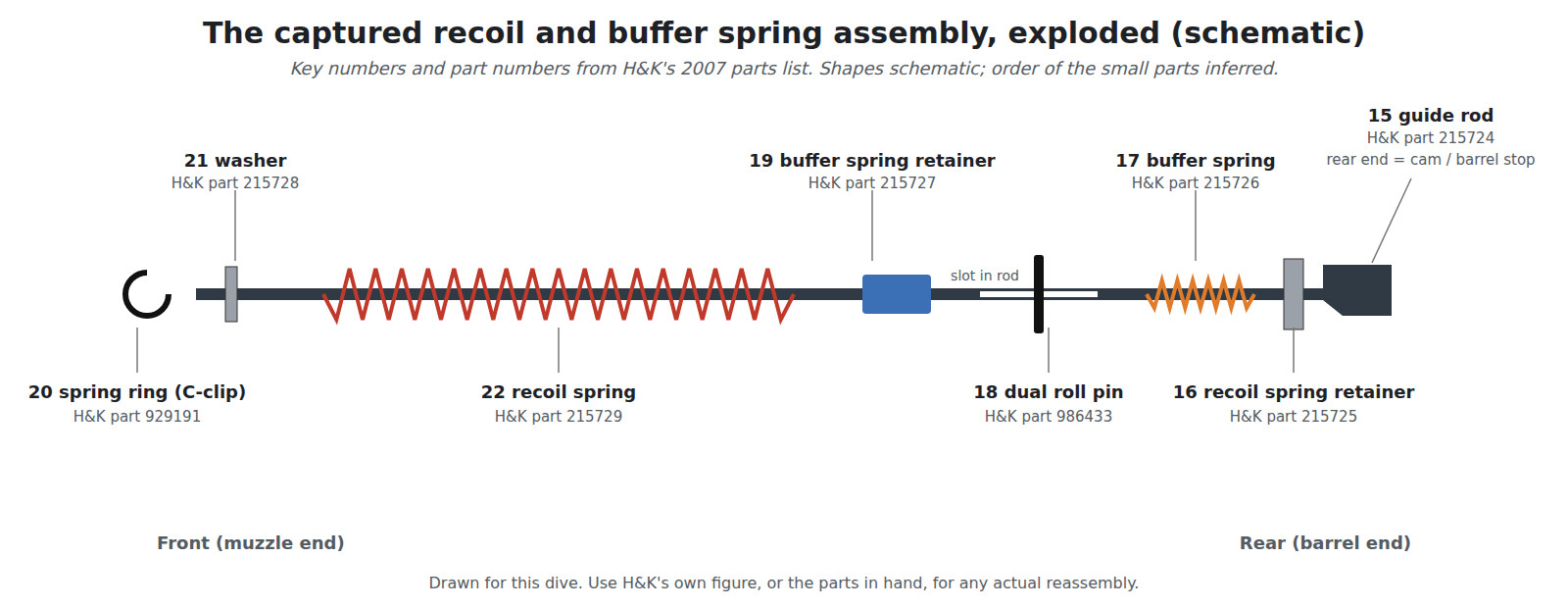
Read against the patent, the parts list has one of everything Figure 3a draws: a guide rod with a cam at its rear end, a long outer breech (recoil) spring, a short buffer spring inside it, a bushing that the buffer spring presses, and a cross pin through a slot that limits how far the bushing can move. The roll pin is the item the manual’s troubleshooting table keeps returning to. Under four separate malfunctions it lists the same possible cause, “Buffer spring retainer roll pin drift”, with the instruction that if the pin is not seated and centred the pistol goes back to H&K.1 A pin that drifts sideways in its hole lets the buffer bushing’s travel change, and it is not a part the manual allows an operator to replace (Volume 5).
H&K’s own drawing of the assembly is the only authoritative view of the order of the parts. The drawing in this volume is a schematic; anyone replacing parts in the assembly needs H&K’s figure, or the parts themselves, not this diagram.
3.8 What “as much as 30 percent” means
H&K’s manual says the Mk 23 has “a mechanical recoil reduction system that reduces recoil forces to the shooter and components of the pistol by as much as 30%”.1 That figure appears in no other document found. The patent gives no figure at all: its argument is qualitative, that H&K’s “studies … have shown that a strong transmission of momentum frequently takes place upon the unlocking of the barrel from the breechblock”, which it calls the “unlocking blow”, and that buffering it is pleasanter for the shooter and kinder to the pistol.2
Physics sets a limit on what any internal buffer can do. The total momentum given to the pistol is fixed by the bullet and the powder gas: about the bullet’s mass times its velocity plus the gas’s share. No spring inside the gun changes that total. What a buffer changes is how the momentum is delivered: spread over a longer time, the same impulse arrives as a lower peak force. So “recoil forces”, in H&K’s phrase, can fall while the felt push stays the same, and the parts take less battering from metal-to-metal stops. H&K’s claim that the system reduces forces “to the shooter and components” is consistent with that reading. The 30 percent figure, its test method and whether it is peak force at the hand, at the frame or something else are not published, and it is reported here as H&K’s.
The patent’s alternative embodiment, Figure 4, fixes the bushing to the guide rod, so that the slide drags the guide rod and barrel along with it at the end of its stroke. H&K reports that “tests carried out with FIG. 4 have shown a subjectively very pleasing recoil”.2 Which embodiment the production pistol follows is not stated anywhere; the parts list’s slotted cross-pin arrangement matches Figure 3, not Figure 4.
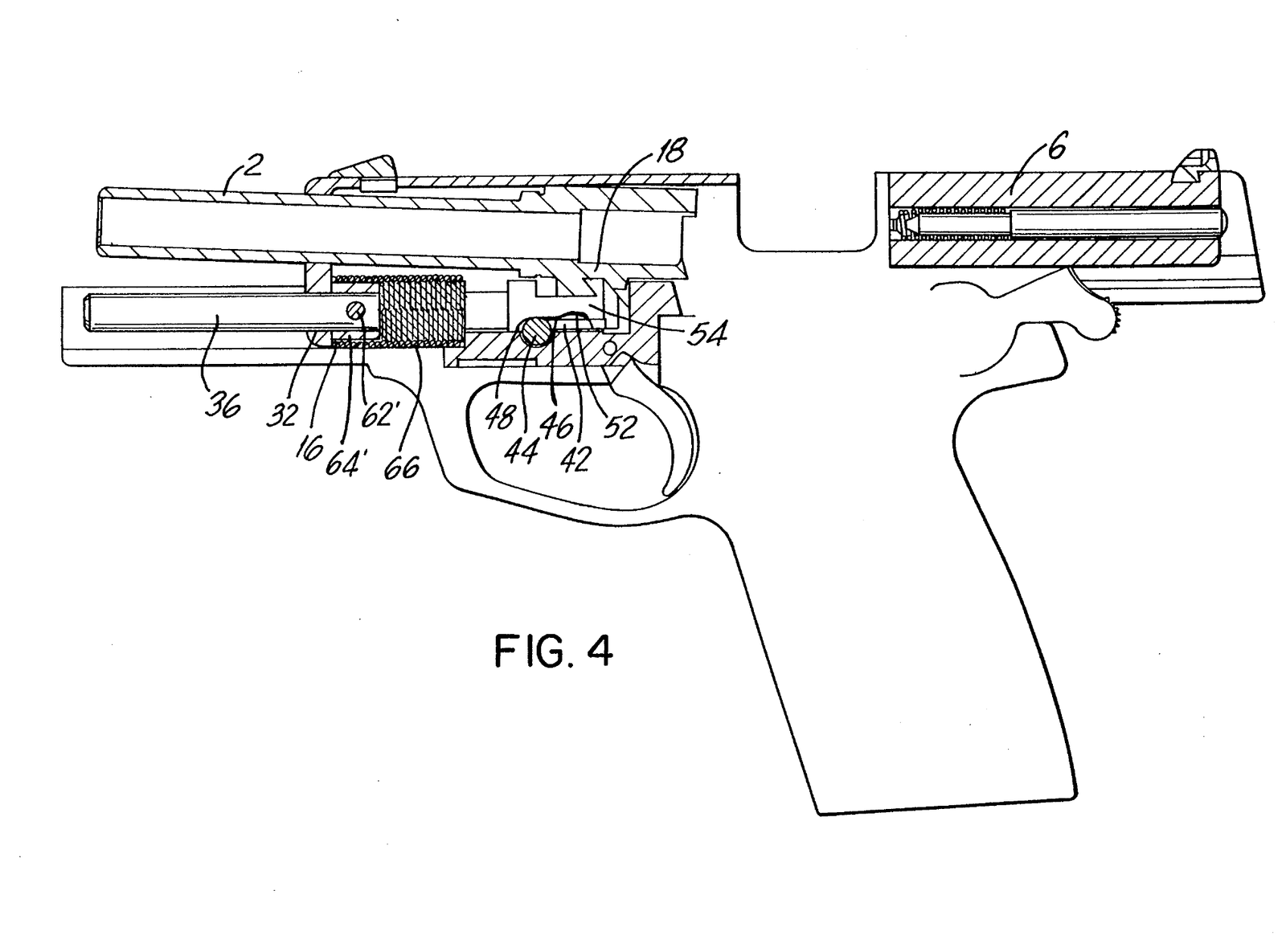
There is a practical cost to the buffered system, and it is the slide force already noted: two springs in series on the slide’s last few millimetres make it stiff to retract by hand. It is also why the Mk 23’s barrel and guide rod must be assembled the right way round in Volume 5’s procedure, with the recoil spring retainer seated on the locking block’s front shelf.
3.9 The barrel: polygonal bore, threaded muzzle, O-ring
The barrel is 149 mm long and threaded at the muzzle for the suppressor. H&K describes its bore as polygonal, spinning the bullet clockwise, with one turn in 378 mm (14.88 in).1 H&K’s polygonal rifling, the cold-hammer-forged profile with rounded “lands” rather than sharp-edged ones, is covered with its patent drawing in this hub’s HK PSG1 dive, Volume 3, and is not re-derived here.

The muzzle thread’s specification is not given in H&K’s manual or on its 2024 product page, which sells the cap (part 970174) only as the “Mark23 .45 ACP thread cap”.4 The Firearm Blog’s 2021 review of the Knight’s suppressor gives it as M16×1 right-hand, in a feature list (“M16x1 RH Threaded O-ring barrel with polygonal bore profile”) and again in a warning to buyers: “the thread pitch on the MK23 is M16x1 RH whereas the USP Tactical barrels are threaded M16X1 LH”.6 The thread matters to anyone fitting a suppressor, and it is the subject of Volume 7. The point to note here is that it is right-hand, the opposite of the left-hand threads reported on H&K’s later .45 pistols; a can or cap for one will not fit the other.
At the rear of the barrel’s front section, H&K fits a rubber O-ring (part 986429) into a groove. The manual says “the O-ring holds the barrel tight in the slide until unlocking” and credits it with the pistol’s accuracy after long use: three pistols “were tested for accuracy after firing over 30,000 rounds … and still met the new pistol accuracy requirement”, and the O-ring “lasts beyond 20,000 rounds and can be replaced by the operator without tools in seconds”.1
What the O-ring does is centre the muzzle end of the barrel in the slide’s front opening while the action is locked. A metal barrel bushing does the same job in a 1911, but a bushing that fits tightly enough to centre the barrel wears and has to be fitted. The O-ring takes up the clearance between barrel and slide with a compliant ring that can be replaced by hand. The troubleshooting table lists “Accuracy degradation” with the cause “Damaged or missing O-ring” and the remedy “Replace O-ring”.1 Because the O-ring is the one wear part on which H&K pins the accuracy, it is the first thing to check on any used Mk 23 (Volume 8).
3.10 The frame and its metal inserts
The frame is a single moulding of “fiberglass reinforced polymer”. Two steel parts are cast into it during moulding: the locking insert, to which the slide release locks the slide, barrel and recoil assembly, and the guiding part, a second rail at the rear.1 “The slide rides on these metal inserts during operation.” The parts list carries the inserts as items 63 and 65, alongside a “trigger guard insert” (64), with no separate part numbers: they are not removable. A cracked or loose insert means a new frame.
The frame carries the pistol’s accessory interface: “A threaded insert is molded into the front face of the trigger guard and the frame is grooved forward of the trigger guard for attachment of an accessory such as a laser aiming device or an illuminator.”1 These grooves are not a Picatinny rail and are not the USP’s grooves either; H&K’s manual warns that “Accessories designed for the Universal Self-loading Pistol (USP) will not work on the Universal Mounting Groves [sic] of the Mark 23.”1 The consequences for buying lights and lasers are in Volume 7.
The trigger guard is “extended, recurved and grooved” for a gloved two-hand grip, and its lower edge is flared on both sides in front of the magazine release to shield it. The front and back straps are checkered. A lanyard loop is moulded into the base of the grip.1
3.11 The fire control: DA/SA with a rebounding hammer
The Mk 23 is double action for the first shot from a lowered hammer and single action thereafter, with an exposed hammer that can also be thumb-cocked. In H&K’s description the trigger mechanism has these parts, from front to back: the trigger (55), which pulls a trigger bar (23) forward; the sear actuator (32), which the trigger bar pivots upward; the sear (30), which holds the hammer; the disconnector (33); the hammer (40) with its strut and spring (42, 43); and a hammer rebound spring (41).1
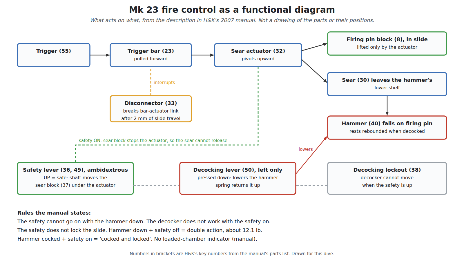
Three details in the manual are specific to this pistol.
- The sear holds the hammer on the lower of two shelves. “The sear is pivoted out of engagement from the lower of the two shelves located on the hammer.”1 The manual does not describe the upper shelf’s function.
- The hammer rests rebounded, not on the firing pin. “On the Mark 23 pistol when decocked (hammer down), the sear is engaged with the hammer at a rebounded stop position not touching the rear of the firing pin.”1 The specification sheet’s phrase “double-action mode with hammer intercept notch” refers to the same feature. A blow to the back of a decocked hammer is caught by the sear before it reaches the pin.
- Restrike. The double action “also permits subsequent hammer strikes on the same chambered round by simply resqueezing the trigger.”1
H&K gives the double-action pull as about 12.1 lb (12.13 lb, 5.50 kg, in the specifications) and the single-action pull as 4.85 lb (2.20 kg; “4.8” in the text).1 The 2024 product page gives 11.47 lb (5.2 kg) and 5.17 lb (2.34 kg) instead (see the last section). The manual also warns that a pistol dropped on its hammer should go back to H&K “to inspect the sear axle”, and lists the rubber hammer spur as an inspection item: a badly cracked spur means the drop-safety may be degraded and the hammer must be replaced at the factory.1
3.12 Safety lever, decocker and why they are separate
The Mk 23’s controls differ from the USP’s in one way that matters more than any other: the safety and the decocker are separate levers. The USP combines them in a single frame-mounted lever whose function depends on the variant (Volume 4). The Mk 23 has an ambidextrous safety lever at the back of the frame and, on the left side only, a decocking lever in front of it.1
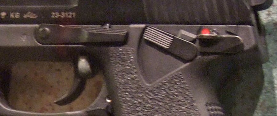
The safety lever is a thumb lever on both sides, “not spring actuated”, held in either position by a spring detent. Up is safe; down is fire. In H&K’s description, “the shaft of the safety lever moves the sear block into a position where it blocks the movement of the sear actuator. The sear actuator, in turn, does not allow the sear to pivot forward and thus the hammer cannot be released. Engaging the safety lever also interrupts the function of the decocking lever and blocks the hammer mechanically.” Two further rules follow from the design: “the safety lever cannot be placed in the safe (up) position when the hammer is down (uncocked)”, and “the safety lever does not restrict the movement of the slide.”1 A red dot on the frame is exposed when the lever is down on fire.
H&K’s manual is candid about the detent. “While there is a spring detent to prevent this, the safety lever can be moved to the ‘fire’ position (down) with a minimal amount of force. This could happen during careless handling or during removal of the pistol from the holster.”1
The decocking lever “allows the operator to quietly lower the cocked hammer”. It is pushed fully down to lower the hammer and springs back up under the decocking spring. “The decocking lever cannot be depressed (and therefore does not allow the hammer to be lowered) if the safety lever is engaged.”1
The two rules together give the pistol two, and only two, carry conditions: hammer down, safety off, for a double-action first shot; or hammer cocked, safety on (“cocked and locked”, in H&K’s feature list), for a single-action first shot.14 Hammer down with the safety on is mechanically impossible, which removes one of the double-action service pistol’s commonest mistakes, a soldier trying to fire a decocked pistol with its safety applied.
Why separate them at all? H&K does not say. Two reasons are evident from the requirement in Volume 1. The decocker lets a hammer be lowered “quietly”, without riding it down with a thumb; and on a pistol meant to be carried cocked with a suppressor fitted, the safety must stay a pure safety, unaffected by the slight pressure that a combined lever’s spring needs. The decocker is on the left only, for a right-handed thumb or a left-handed trigger finger.
3.13 Passive safeties: firing pin block and disconnector
Two safeties act without the shooter’s involvement.1
The firing pin block is in the slide, spring-loaded downward into a recess in the middle of the firing pin. “Only when the trigger is depressed can the sear actuator push the firing pin block upward against the downward pressure exerted by the firing pin block spring.” When the slide starts back after a shot, the block drops back into the pin’s recess. It is the protection against firing when the pistol is dropped, when the hammer is struck, or when the slide slams forward.
The disconnector “prevents the release of the hammer unless the slide is fully forward and/or the trigger is reset”. It does so by disconnecting the trigger bar from the sear actuator. “The disconnector is engaged (operating) after the slide has moved 2mm to the rear.” With the slide fully forward, the disconnector’s leading edge sits in a recess in the underside of the slide; as the slide moves, it presses the disconnector down into engagement.
The manual’s function test for the disconnector, in Volume 5, says to pull the slide back “3/16 inch (2 mm)”. Three-sixteenths of an inch is 4.8 mm. The 2 mm figure agrees with the description above; the inch figure is a conversion error in the manual.1
3.14 Magazine, slide release and the missing chamber indicator
The magazine is sheet steel, double-column, 12 rounds, with numbered viewing holes in the back of the body. A 10-round magazine (part 215670) with its own body, follower plate, floorplate and spring was also made, and H&K still listed both in 2024.14 The 10-round magazine’s floorplate is removed by depressing the locking detent and squeezing two locking tabs; the 12-round one by depressing the detent and sliding the floorplate forward (Volume 5). The magazine release is an ambidextrous lever at the rear of the trigger guard, engaging a notch “in the upper third of the magazine housing”.
The slide release is the slide stop. “As a slide stop, it is depressed upward by the magazine follower or the operator’s finger as the slide travels rearward.” It is also the disassembly pin, removed from the left side “when the slide is held rearward” with its front end aligned on a recess.1
There is no loaded-chamber indicator. H&K’s manual is explicit: “The Mark 23 pistol does not have a loaded chamber indicator. The extractor does not act as a loaded chamber indicator.”1 This is one of the places where H&K’s later web pages say the opposite (below). A chamber check on a Mk 23 is done by retracting the slide and looking.
3.15 Where H&K’s documents disagree
H&K has described the commercial Mark 23 in several places that could be checked for this dive: its web pages as captured in January 2000 and October 2004; the 2007 operator’s manual; the “general” and “specs” pages of hk-usa.com as captured in March 2014; and the product page as captured in December 2024. They disagree in ways that matter.7819104 The web wording was in place by October 2004, three years before the manual’s revision, so the manual is the later document and it is the one that contradicts the web pages.
Table 3 — Where H&K's documents disagree
| Item | 2007 manual | 2004 and 2014 web pages | 2024 product page |
|---|---|---|---|
| Loaded-chamber indicator | ”does not have a loaded chamber indicator. The extractor does not act as a loaded chamber indicator." | "Extractor doubles as a loaded chamber indicator” | Same as 2004 and 2014 |
| Lock | Not in the parts list | ”Patented Lock-Out Safety device” | Same as 2004 and 2014 |
| Finish | ”special maritime surface coating" | "Corrosion resistant blued finish” | Same as 2004 and 2014 |
| Frame width | 1.58 in (38.8 mm) | 1.53 in (2004); 1.54 in, 39 mm (2014) | 1.53 in (39 mm) |
| Sight radius | 7.76 in (197 mm) | 7.76 in (2004); 7.68 in, 195 mm (2014) | 7.76 in (195 mm) |
| Weight | 2.66 lb (1.21 kg) with empty 12-round magazine | 2.42 lb (2004); 2.43 lb (1.1 kg) “with magazine” (2014) | 39.36 oz (1,120 g) “with magazine” |
| Trigger pull, SA | 4.85 lb (2.20 kg) | Not given (2004); 5.17 lb, 2.34 kg (2014) | 5.17 lb (2.34 kg) |
| Trigger pull, DA | 12.13 lb (5.50 kg) | Not given (2004); 11.47 lb, 5.2 kg (2014) | 11.47 lb (5.2 kg) |
Three of these are more than rounding.
- The chamber indicator. The manual, which an owner reads to operate the pistol, says the extractor is not an indicator; the web pages say it is. H&K’s October 2004 page for the USP Tactical carries the same two lines word for word, “Extractor doubles as a loaded chamber indicator” and “Patented Lock-Out safety device”, which suggests the Mark 23’s web feature list was built from the USP’s.11 The safe practice is the manual’s: check the chamber by looking.
- The “Lock-Out Safety device”. No such part appears in the Mark 23 manual’s text or in its exhaustive parts list, and H&K’s pages do not describe it. Whether any commercial Mark 23 was ever fitted with one was not established for this dive; the claim is not repeated as a feature.
- The finish. The manual’s “special maritime surface coating” and the web pages’ “corrosion resistant blued finish” may both be true of different years. Bartocci reports that the first commercial pistols had the military maritime finish and that “later commercial pistols would use the same finish as the USP”.12 The finishes, and how to tell them apart, are in Volume 4.
The 2024 page’s sight radius is internally inconsistent: 195 mm is 7.68 in, not 7.76 in, which is the manual’s 197 mm. H&K’s German group site in 2010 gave the Mk 23’s sight radius as 195 mm.13 The weights differ by what is included and are not compared further.
References
Footnotes
-
Heckler & Koch, Inc., Mark 23 Pistol .45 ACP operator’s manual (“Revised March 2007”; PDF dated 22 August 2008), Sections 1 to 4 and 9, parts list p. 34. Wayback capture of 11 August 2011, https://web.archive.org/web/20110811030250/http://www.hk-usa.com/-images/shared/Mark%2023_Ops_Manual_2008.pdf, consulted 2026-10-18. ↩ ↩2 ↩3 ↩4 ↩5 ↩6 ↩7 ↩8 ↩9 ↩10 ↩11 ↩12 ↩13 ↩14 ↩15 ↩16 ↩17 ↩18 ↩19 ↩20 ↩21 ↩22 ↩23 ↩24 ↩25 ↩26 ↩27 ↩28 ↩29 ↩30 ↩31 ↩32 ↩33 ↩34 ↩35 ↩36 ↩37 ↩38 ↩39 ↩40 ↩41
-
US Patent 5,309,815, T. Möller, R. Brandl and H. Weldle (and, by certificate of correction of 28 February 1995, H. Krieger), assignors to Heckler und Koch GmbH, “Firearm, particularly handgun”, filed 24 March 1992, German priority 25 March 1991, issued 10 May 1994, https://patents.google.com/patent/US5309815A/en, consulted 2026-10-18. ↩ ↩2 ↩3 ↩4 ↩5 ↩6 ↩7 ↩8 ↩9 ↩10 ↩11
-
VISIER, “Portrait: 20 years of Heckler & Koch USP”, all4shooters.com, 17 June 2013, https://www.all4shooters.com/en/shooting/pistols/heckler-koch-semiautomatic-pistol/, consulted 2026-10-18. ↩
-
Heckler & Koch USA, “MARK 23” product page, Wayback capture of 28 December 2024, https://web.archive.org/web/20241228154506/https://hk-usa.com/hk-models/mark-23/, consulted 2026-10-18. ↩ ↩2 ↩3 ↩4 ↩5
-
US Patent 5,581,046, H. Weldle and H. Albrecht, assignors to Heckler & Koch GmbH, “Hand-held firearm with recoil attenuation”, German priority 2 December 1993, issued 3 December 1996, https://patents.google.com/patent/US5581046A/en, consulted 2026-10-18. ↩
-
Pete, “Silencer Saturday #178: H&K and KAC MK23 – The Most Famous Suppressor Combo?”, The Firearm Blog, 29 May 2021, https://www.thefirearmblog.com/blog/2021/05/29/hk-kac-mk23, consulted 2026-10-18. ↩
-
Heckler & Koch, Inc., “Mark 23, USP Tactical and Match” page, Wayback capture of 28 January 2000, http://web.archive.org/web/20000128213444/http://www.hecklerkoch-usa.com:80/Pages/mk23.html, consulted 2026-10-18. ↩
-
Heckler & Koch, Inc., “MARK 23” page, Wayback capture of 16 October 2004, http://web.archive.org/web/20041016095828/http://www.hecklerkoch-usa.com:80/handguns/mk23.html, consulted 2026-10-18. ↩
-
Heckler & Koch USA, “mark 23 :: general”, Wayback capture of 9 March 2014, https://web.archive.org/web/20140309124324/http://www.hk-usa.com/civilian_products/mark23_general.asp, consulted 2026-10-18. ↩
-
Heckler & Koch USA, “mark 23 :: specs”, Wayback capture of 9 March 2014, https://web.archive.org/web/20140309040932/http://www.hk-usa.com/civilian_products/mark23_specs.asp, consulted 2026-10-18. ↩
-
Heckler & Koch, Inc., “The USP Tactical” page, Wayback capture of 18 October 2004, http://web.archive.org/web/20041018000623/http://www.hecklerkoch-usa.com:80/handguns/usptactical.html, consulted 2026-10-18. ↩
-
Christopher R. Bartocci, “MK23 Mod 0: The Crew-Served Pistol”, Small Arms Defense Journal vol. 5 no. 2 (2013); web edition of 11 August 2023, page 2, https://sadefensejournal.com/mk23-mod-0-the-crew-served-pistol/2/, consulted 2026-10-18. ↩
-
Heckler & Koch GmbH, pistol product listing, Wayback capture of 29 July 2010, http://www.heckler-koch.de/HKWebText/detailProd/1925/104/4/21, consulted 2026-10-18. ↩
Comments (0)