Borchardt C-93 · Volume 4
How It Works: The Toggle, the Rollers and the Double Closing Spring
The full cycle of operation part by part, from the patent, the 1896 US Navy description and the factory's own manuals, with the part numbers the factory used
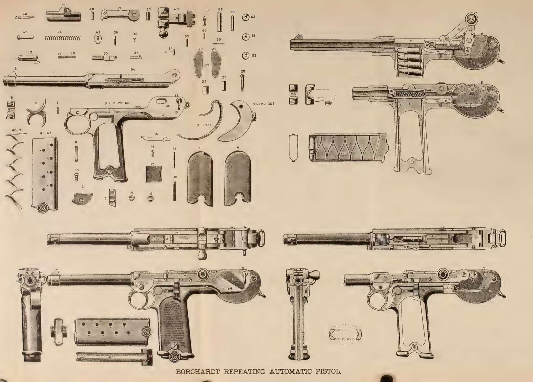
This volume takes the C-93 apart on paper. It is written from four period documents, which agree with one another closely because they share a source, and it uses the factory’s own names and part numbers throughout. Where modern usage differs from the factory’s, as it does for the springs, the factory term is used and the modern one explained.
4.1 Sources for this volume
Table 1 — Sources for this volume
| Source | Date | What it gives |
|---|---|---|
| US Patent 571,260, Borchardt, “Recoil Magazine-Pistol” | Filed 1893, issued 1896 | The principle, in Borchardt’s words, with sections closed (Fig. 4) and open (Fig. 6) |
| Ludw. Loewe & Co., Repeating Pistol (System Borchardt), English edition | Before 1897 | The factory’s full description, numbered parts list 1–71, specifications |
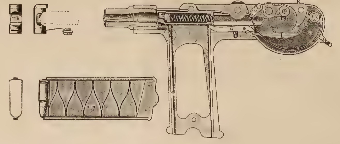
| DWM, Automatic Repeating Pistol, Borchardt Patent, English edition | 1897 or later | A revision of the Loewe text with new plates, a shorter parts list and the “properties and advantages” |
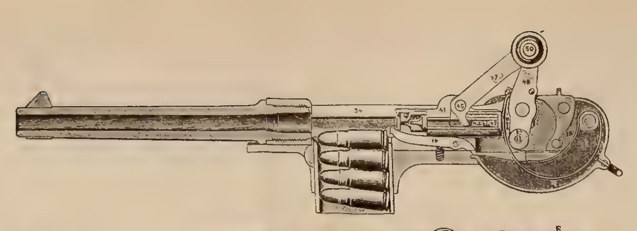
| US Office of Naval Intelligence, General Information Series No. XV | July 1896 | An independent restatement with the full plate above, the barrel’s recoil distance, and ballistic data |
| Scientific American, “Improved Repeating Pistol” | 3 August 1895 | The same parts numbering, credited to the London weekly Engineering |
The Loewe manual is the fullest, and where a passage below is quoted without other attribution it is the Loewe English text, transcribed from the page images published by the collector site Land of Borchardt.1 The German patent, DRP 75,837, is quoted from its machine-read text; its drawings could not be obtained.2
4.2 The factory’s specification
Table 2 — The factory's specification
| Item | Factory figure | Other published figures |
|---|---|---|
| Calibre | 7.65 mm | — |
| Barrel length | 190 mm; 154 mm short version in the Loewe manual | 195 mm (English Wikipedia); 165 mm (German Wikipedia); 7⅝ in and 7.7 in (auction copy) |
| Rifling | 4 grooves, one turn in 250 mm, right hand | — |
| Weight of pistol | 1,275 g (190 mm barrel); 1,250 g (154 mm barrel) | 2.75 lb, 1,247 g (ONI 1896); 1,350 g (WTS label); 1,160 g (English Wikipedia) |
| Weight of empty magazine | 55 g | — |
| Stock, leather holster and strap | 425 g | — |
| Distance between sights | 315 mm | — |
| Cartridge length | 35 mm | 1.4 in (ONI) |
| Muzzle velocity | 400 m/s | 1,300 ft/s (ONI); 360 m/s (WTS label); 390 m/s (English Wikipedia) |
| Magazine capacity | 8 | — |
| Overall length | Not given by either manual | 355 mm (WTS label; English Wikipedia); “1 foot” (ONI) |
| Barrel recoil | Not given | 0.118 in, about 3.0 mm (ONI) |
The factory figures are from the DWM manual’s table “Dates referring to the Borchardt-Repeating Pistol” and the corresponding Loewe table.31 The disagreements are given rather than resolved, with two observations. The 190 mm and 195 mm figures may both be right for different measuring conventions, since the barrel screws into the receiver and its visible length depends on where the measurement starts; that is a reading, not a documented explanation. And the overall length is surprisingly poorly attested: neither manual gives one, the ONI’s “1 foot” is a round figure, and the 355 mm in circulation appears with a source only on a museum label.
4.3 Four groups: barrel and receiver, lock, grip, firing mechanism
The Loewe manual opens its description by dividing the pistol into groups, and the division is the right way to understand it:
“The principal parts are: The barrel 1 screwed into the forkshaped receiver 34, which latter is fitted up to slide in the guides and casing on top of the grip, The lock, consisting of the breech-block 41 with firing-bolt 43, the togglejoint 47–49 springs, pins, etc. The grip 3, which forms one piece with the trigger-guard, guides and casing for the receiver and lock-mechanism, The firing-mechanism composed of the trigger 10, sear 35, safety 7, etc. and finely [sic], The cartridge-magazine 61–67 with feeding spring 68–71.”1
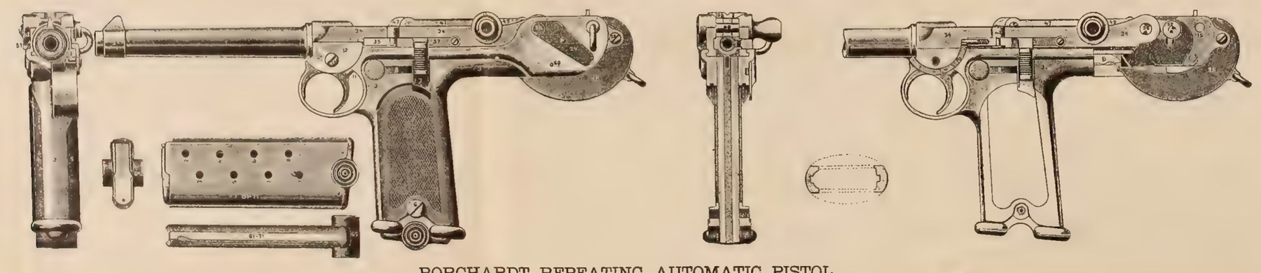
The DWM manual puts it more vividly. The barrel, receiver and lock make “a complete single loader”, and “this complete single loader is fitted into a grip in such a way, that it slides therein parallel to the bore of the barrel; the grip may thus be compared to a guncarriage.”3
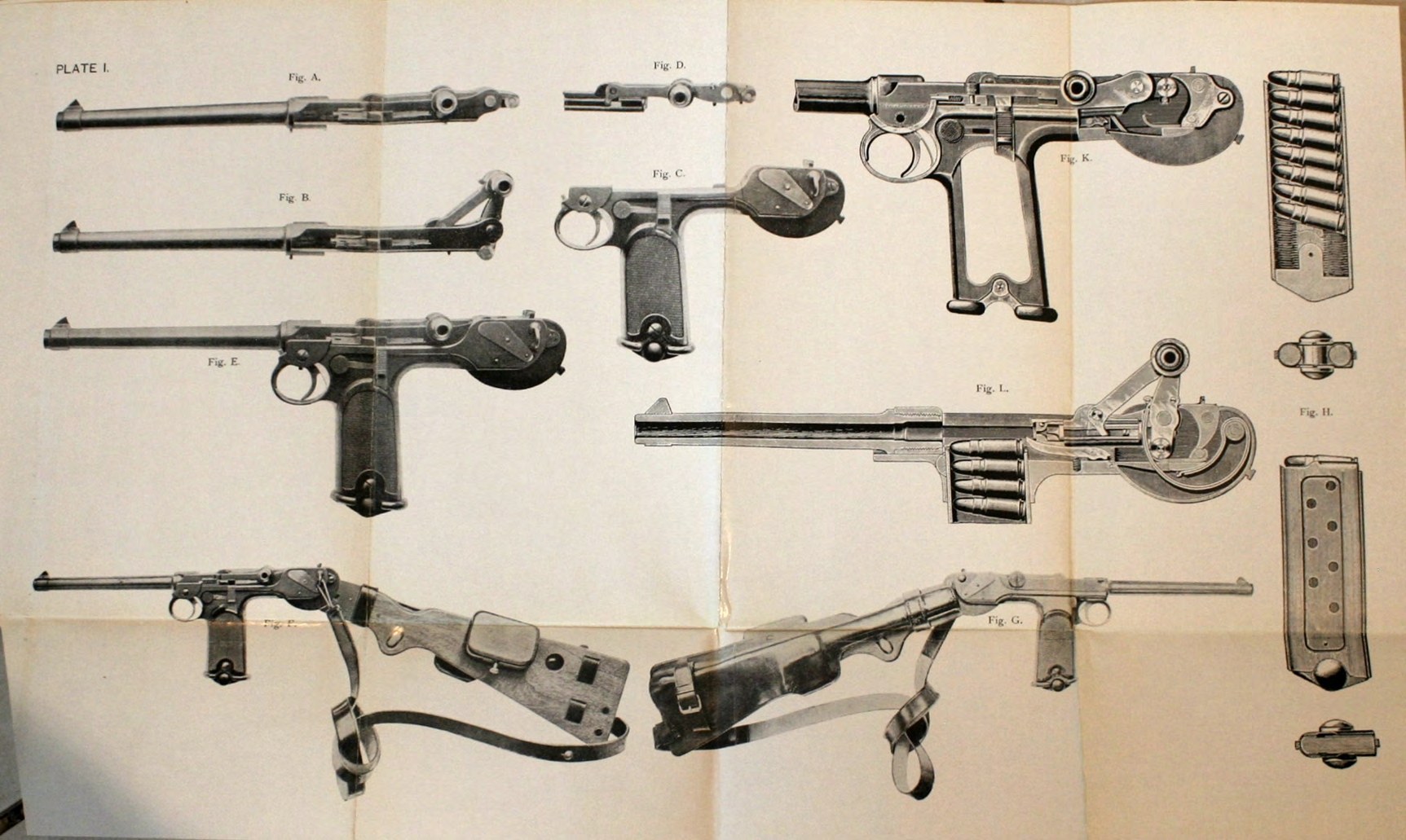
That image is the key to the whole pistol. The C-93 is a small recoiling gun mounted on a carriage. The barrel, the receiver it screws into, the breechblock, the toggle and the sear all slide back together on the grip when the pistol fires, as a gun barrel recoils on its carriage. The grip carries everything that does not move: the trigger, the safety, the magazine, the ejector, the rear sight, the springs, and the curved surface at the back that turns the recoil into an opening stroke. The DWM manual calls the grip, in fact, the “grip (gunrest)”, and its Plate I shows the two halves separately: “Fig. A & B. The firing system proper, in a closed and opened position, consisting of barrel, receiver, locking mechanism, connecting pin and sear”; and “Fig. C. The grip (gunrest) in which the complete firing system slides. The grip serves by means of the curve in the rear as buttpiece for opening the breech.”3
4.4 The parts, by the factory’s numbers
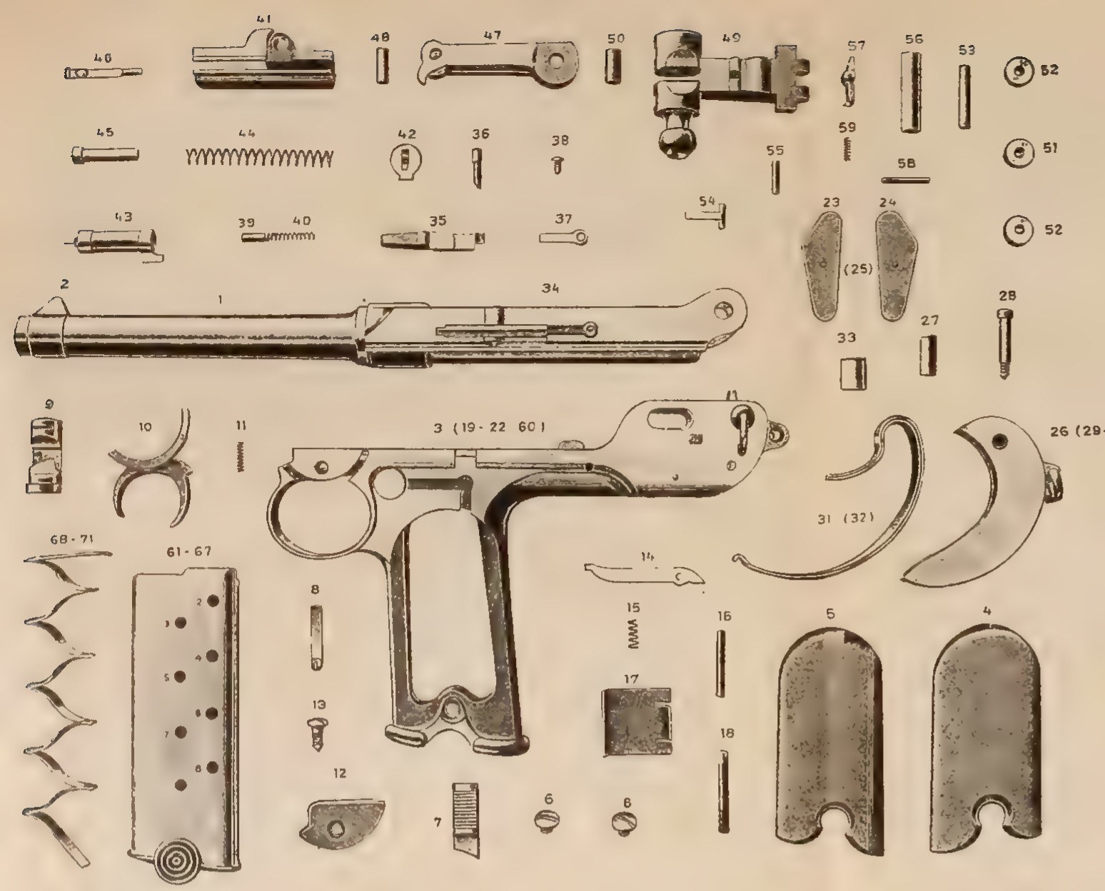
The numbered parts list in the Loewe manual is the complete inventory of the pistol, and anyone restoring, copying or simply reading about one needs it. It is reproduced below from the Loewe English list, with the groupings the factory used.1 Numbers 20 to 22, 25 and 60 are not individually named in the parts of the list transcribed for this dive; the ONI plate labels the grip “3 (19-22 60)”, which places them among the parts fixed permanently to the grip, and labels the cover plates “23, 24 (25)”.4
Table 3 — The parts, by the factory's numbers
| No. | Part | Group |
|---|---|---|
| 1 | Barrel | Barrel and receiver |
| 2 | Front sight, “one piece, the sight is soldered on” | Barrel and receiver |
| 34 | Receiver, forked | Barrel and receiver |
| 3 | Grip, with trigger guard, guides and casing | Grip |
| 19 | Butt (the curved rear piece the rollers strike) | Fixed to grip |
| 4, 5 | Right and left cheekpieces (grip panels) | Grip |
| 6 | Cheekpiece screws | Grip |
| 7 | Safety | Firing mechanism |
| 8 | Spring for magazine holder and safety | Firing mechanism |
| 9 | Magazine holder (catch) | Firing mechanism |
| 10 | Trigger | Firing mechanism |
| 11a, 11b | Trigger spring and pin, one piece with trigger | Firing mechanism |
| 12, 13 | Trigger cover and screw | Firing mechanism |
| 14, 15, 16 | Ejector, ejector spring, ejector pin | Grip |
| 17a, 17b | Double recoil spring | Grip |
| 18 | Recoil spring pin | Grip |
| 23, 24 | Right and left cover plates | Grip |
| 26 | Spring box | Spring box |
| 27, 28 | Spring box bushing and screw | Spring box |
| 29, 30 | Swivel and swivel pin, one piece with the spring box | Spring box |
| 31a, 31b | Double closing spring | Spring box |
| 32 | Closing spring rivet | Spring box |
| 33 | Closing spring bushing | Spring box |
| 35 | Sear | Firing mechanism, carried on the receiver |
| 36, 37, 38 | Sear screw, sear spring, sear crosspin | Firing mechanism |
| 39, 40 | Sear pin and sear pin spring, “contained in the sear” | Firing mechanism |
| 41 | Breechblock | Lock |
| 42 | Breechblock screw (plug) | Lock |
| 43, 44 | Firing bolt (striker) and firing bolt spring | Lock |
| 45 | Firing bolt spring reinforce (reading uncertain on the scan) | Lock |
| 46 | Extractor | Lock |
| 47, 48 | Front link and its pin | Lock |
| 49, 50 | Rear link and its pin | Lock |
| 51 | Middle friction roll | Lock |
| 52 | Two outer friction rolls | Lock |
| 53 | Friction roll pin | Lock |
| 54, 55 | Stirrup and stirrup pin | Lock |
| 56 | Connecting pin | Lock |
| 57, 58, 59 | Catch lever, pin and spring | Lock |
| 61, 62 | Left and right magazine side plates | Magazine box |
| 63, 64 | Front and rear ribs | Magazine box |
| 65 | Bottom piece, wood | Magazine box |
| 66, 67 | Long and short bottom piece pins | Magazine box |
| 68 | Spring top plate | Magazine spring |
| 69 | Eight spring leaves | Magazine spring |
| 70 | Bottom spring leaf | Magazine spring |
| 71 | Nine spring rivets | Magazine spring |
The Loewe list groups 41 to 59 together as “one complete lock-mechanism”, and the DWM manual’s shorter list of thirty items sells it the same way: “2. Breechblock with togglejoint, pins, stirrup, friction rolls and catchlever.”3 The factory regarded the lock as one assembly, and Volume 6 shows that its instructions keep it that way.
4.5 The cycle, step by step
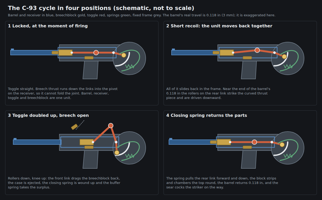
1. Locked, ready to fire. The barrel, receiver, breechblock and toggle are one unit, standing forward in the grip. The breechblock is held against the cartridge head by the two links, which in this position are in line. Scientific American, following Engineering, puts it simply: the breechblock “is held up firm against the force of the explosion of the charge by means of two links 47 and 49 … which at the time of firing are in line”.5 The front link is pinned to the breechblock; the rear link is pinned to the receiver by the connecting pin 56. The knee where the two links meet “straddles the receiver on both sides; on the left it forms a small knob to facilitate the opening of the mechanism by hand, on the right it carries the catch-lever 57, which snaps over a corresponding catch on the grip, when the parts are closed.”1
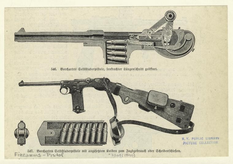
2. Short recoil. On firing, the whole unit moves back in the grip. “The recoil drives the barrel and breech-mechanism to the rear, the forkshaped receiver being guided in the casing which forms the upper part of the grip. Through the rear end of the receiver passes the connecting pin 56, which joins the rear link 49 of the togglejoint to the receiver, the ends of this connecting pin project through elongated slots in the casing and limit the recoil-motion; the plates 23 and 24 cover the elongated slots and secure the connecting pin sideways.”1 The ONI gives the distance: “The total recoil is 0.373-inch; that of the receiver and barrel 0.118-inch.”4 The barrel and receiver therefore travel about 3.0 mm. What the larger figure of 0.373 inch, about 9.5 mm, measures is not explained in the text; it is quoted as printed.
3. Unlocking. The rear link 49 does not end at its pivot. Behind the connecting pin it continues as an arm wide enough to fill the casing, and “it carries 3 friction-rolls 51 and 52”, a middle roller and two outer ones on one axis.1 As the unit moves back, those rollers meet the fixed curved butt piece 19 at the rear of the grip. “The frictions-rolls of the rear link strike against the curved butt and are forced downward, the middle joint of the toggles is raised and the breech-block recedes”.1 Borchardt’s patent says the same in its own words: the rollers “strike the thrust-piece a’, and by reason of its rounded or cam shape are forced downward, thereby bending the toggle-joint, throwing its central portion upward, and pulling back the bolt”.6 The German patent: “Dadurch hebt sich das Froschgelenk um sein Mittelgelenk nach oben”, the toggle rises about its centre joint.2 The front of the curved piece is, in the patent’s words, “that of a cam, preferably concavely curved”.6
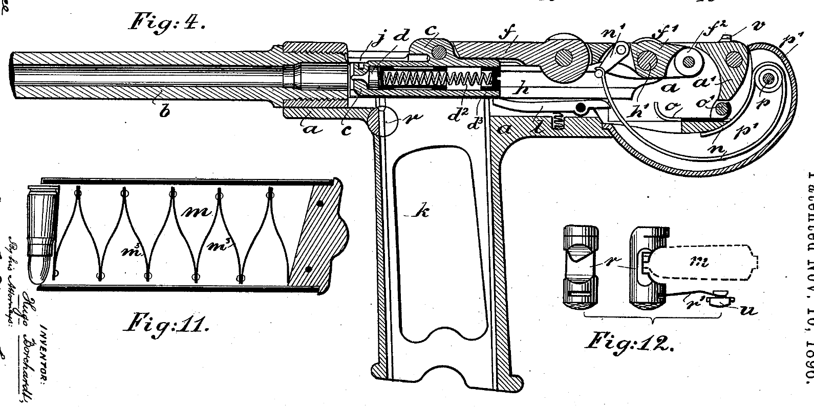
4. Extraction and ejection. The breechblock “recedes taking with it the empty shell by means of the extractor until it reaches the end of its motion where the ejector strikes the shell from below and throws it out.”1 While the block travels back, the front link’s projecting nose on the left side draws the striker back with it, and the top cartridge in the magazine rises into the path of the block.
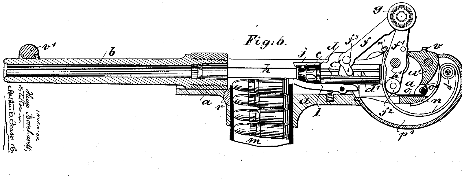
5. Buffering. The pistol has more energy than it needs to open. “The recoil imparts more than sufficient momentum to the moving parts to overcome the tension of the firing-boltspring and closing spring, the surplus is stored up by the recoil spring upon which the friction rolls impinge at last. The force of the recoil wich [sic] is thus distributed reduces the shock to the hand considerably.”1 The “recoil spring” here is the factory’s name for a buffer at the bottom rear of the grip, not the spring that returns the action; see below.
6. Return and feeding. “As soon as the force of the recoil is neutralized, the stored energies in the springs commence to operate. The closing spring supported at first by the impulse of the recoil-spring draws the link 49 of the toggles forward and downward, the breech-block pushes the top cartridge into the barrel, which latter has also been moved forward, and the firing bolt is arrested and held cocked by the sear.”1 As the block closes, the knee comes down, the links straighten, the catch lever snaps over its catch, and the barrel and lock are back in battery.
7. Ready to fire again. “In firing it is only necessary to pull the trigger; the pistol remains loaded and cocked after each shot.”3 The DWM manual puts the whole sequence at “one twentyfifth part of a second”.3
4.6 Why the toggle stays shut
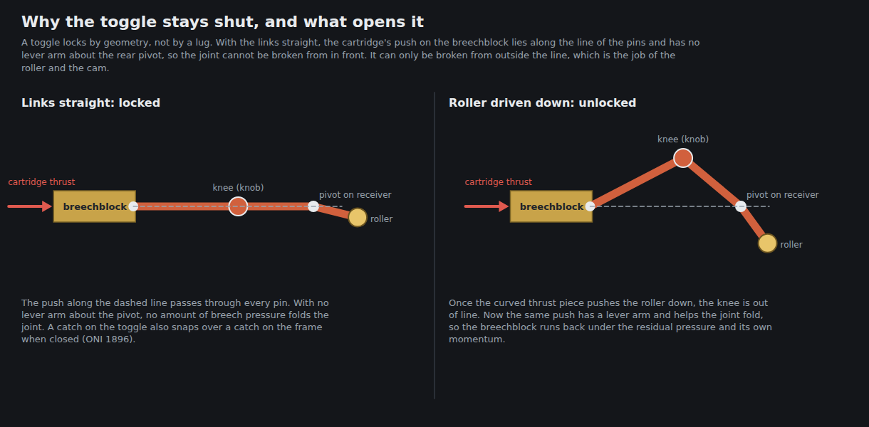
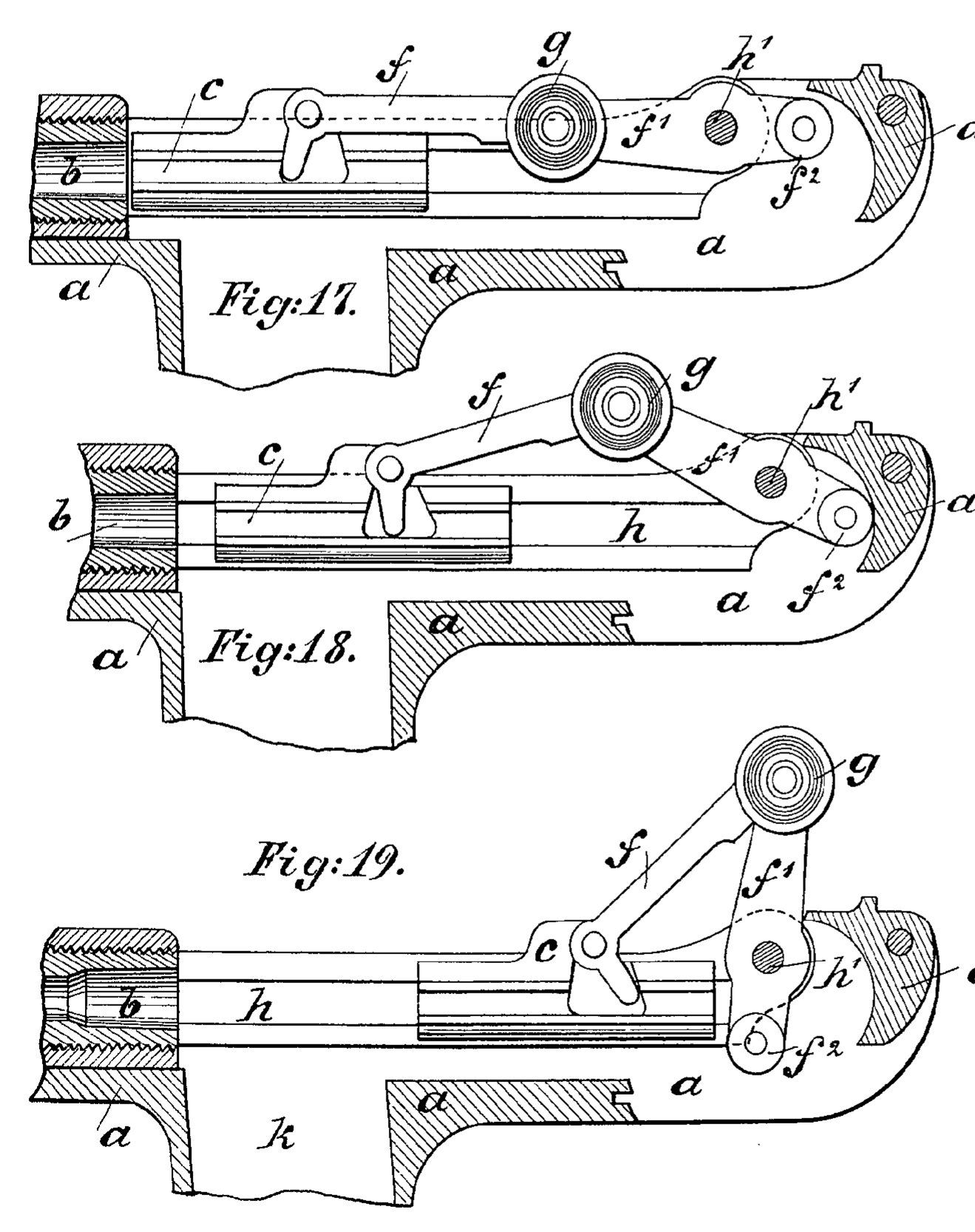
A toggle lock has no lug and no shoulder. It holds because of geometry. When the two links are straight, the force of the cartridge on the breechblock acts along the line of the pins, and a force along that line cannot turn either link about its pivots; it can only compress them. The joint can be folded only by a force from outside that line, and in the C-93 that force comes from the rollers meeting the curved butt piece.
That is also why the barrel and lock must recoil together first. The DWM manual makes the point as a selling claim: “The breech of this complete firing system remains perfectly closed during its first part of the recoil in the grip. During the last of the recoil, after the bullet has left the barrel and after the propelling gases have lost their pressure upon the breech, the opening of the breechmechanism takes place.”3 The roughly 3 mm of barrel travel before the rollers do their work is the delay that keeps the breech shut while pressure is high.
Two further features help the toggle stay closed. The first is the catch lever 57 on the right of the knee, which “snaps over a corresponding catch on the grip, when the parts are closed”.1 The second is the closing spring, which pulls the rear link “forward and downward” and so holds the knee down against any tendency to rise.
Whether the C-93’s closed toggle sits exactly on the line of the pins or slightly below it, as Luger’s does, is not stated in Borchardt’s patent or in either manual. Luger’s own patent of 1900 describes his toggle resting with its “central hinge … a little below the end points of the joint”, on what he calls the “knee-press” principle, and adds that “the link connection is partly carried out in manner already known”.7 Whether Borchardt’s did the same would have to be measured from a pistol or from the German patent drawings; it is not asserted here.
4.7 The springs: closing spring, recoil spring, and the “clock spring” confusion
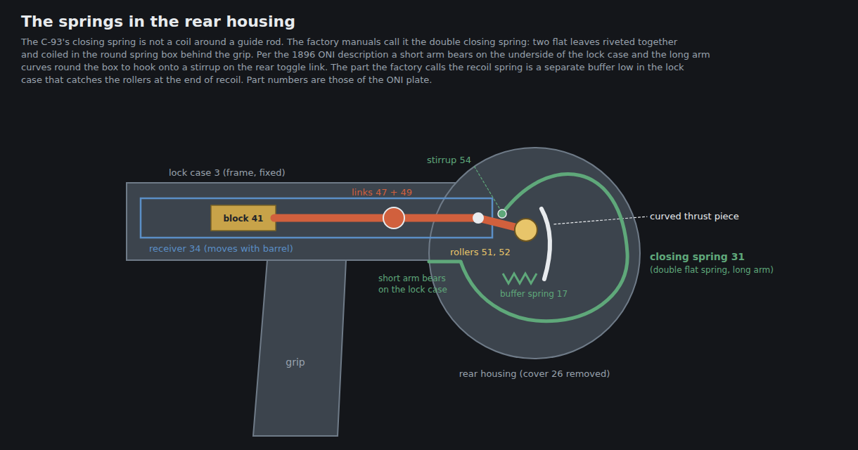
The C-93’s springs are the most consistently misnamed part of it, and the factory terms clear the confusion up.
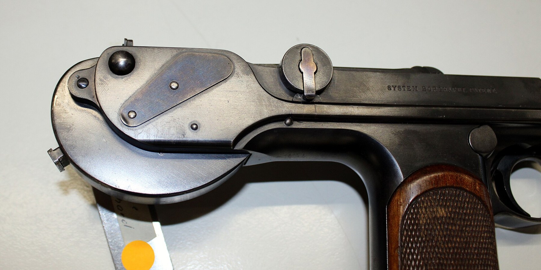
The closing spring, 31a and 31b. This is the spring that closes the action, and it lives in the round housing behind the grip. The factory calls it the “double closing spring”: two flat leaves, 31a and 31b, joined by the rivet 32 and wound round the bushing 33 inside a separate, removable spring box 26.1 The Loewe manual describes the arrangement: “The casing of the grip is closed at the rear by a curved buttpiece, 19. To this is fastened between two ears by means of a screw and bushings the spring-box 26 with the closing-spring 31. The short arm of the spring 31 rests against the underside of the receiver-casing, while the other arm passes around the bushings in a long curve to hook unto the stirrup 54 which is jointed to the rear link of the toggles.”1 The DWM list calls the same assembly “Springbox with double closing spring, pin, springroll and boxbushing”.3
Collectors call this the “clock spring” or “watch spring”, from its coiled flat form, and some popular accounts call it the “mainspring”. It is neither in the factory’s vocabulary, and calling it the recoil spring, as some modern accounts do, collides directly with the factory’s use of that term for a different part. The WTS Koblenz label describes it as a spring formed “als Spirale”, as a spiral, in the round extension of the housing.8
The recoil spring, 17a and 17b. The factory’s “double recoil spring” is a buffer. It is “in the rear at the bottom of the receiver-casing”, held by the pin 18, and its job is to absorb the surplus energy when the rollers reach the end of their travel and then to give the returning parts their first push.1 Borchardt’s patent calls it the “buffer-spring” and describes it as “secured by a pin within the lower rear part of the frame”, with “its front portion … bent upward and … forked to allow the spring n to enter the gap thus formed.”6 The DWM manual lists it as part of the grip: “Grip, with rear sight, ejector and double recoil spring.”3
The striker spring, 44, is a coil spring inside the hollow striker, and is the only coil spring among the three main springs. The German patent uses Schraubenfeder, coil spring, only for it.2
The patent’s version differs in detail. In Borchardt’s patent the closing spring pivots on a screw p in the rear housing, its shorter arm bearing against the frame and its longer arm sweeping “around in a bow” to engage “a link n’, which is pivoted to the rear toggle-link f’”.6 The production pistol put the spring in a removable box and called the link a stirrup. The principle is the same.
Luger’s patent shows what happened to the idea next: his closing spring is “a plate-spring lying in the neck of the butt”, S-shaped, connected to the rear link through “a swinging arm”.7 The English encyclopaedia’s Luger article records that the 1906 New Model Parabellum finally replaced the “flat laminated main spring” with a coil.9
4.8 Breechblock, striker and extractor
“The breech-block is guided by means of two ribs and corresponding grooves in the receiver. The left of these ribs on the breech-block is again grooved for the free passage of the nose of the sear 35, which swinging in the left side of the receiver engages the lug of the firing-bolt, whenever the mechanism is being closed. The firing-bolt 43 forms a hollow cylinder with a projecting lug on one side, it is propelled by a spiral spring 44 resting against the screw-plug 42 which closes the rear opening of the breech-block. The front end of the latter is countersunk for the head of the cartridge, it is provided on top with the spring extractor 46 and has a slot at the bottom to allow the ejector 14 to rise when its motion to the rear is nearly completed.”1
The C-93 is striker fired; it has no hammer. The striker is cocked during opening: the front link “has a projecting nose on the left side, which serves to draw back the firing-bolt as soon as the opening of the breech takes place”, and the sear catches the striker’s lug as the breech closes.1 The DWM manual counts positive cocking among the pistol’s virtues: “The firing bolt is positively drawn back at each opening of the breechmechanism.”3 It also claims a measure of protection against a pierced primer: “In case of a punctured primer, the gases pass out forward of the firingbolt-body.”3
The breechblock screw 42, which closes the rear of the block and holds the striker spring, needs “the special screw-driver having a central stud” to remove, according to the DWM takedown instructions.3 Volume 6 has the procedure.
4.9 Ejector
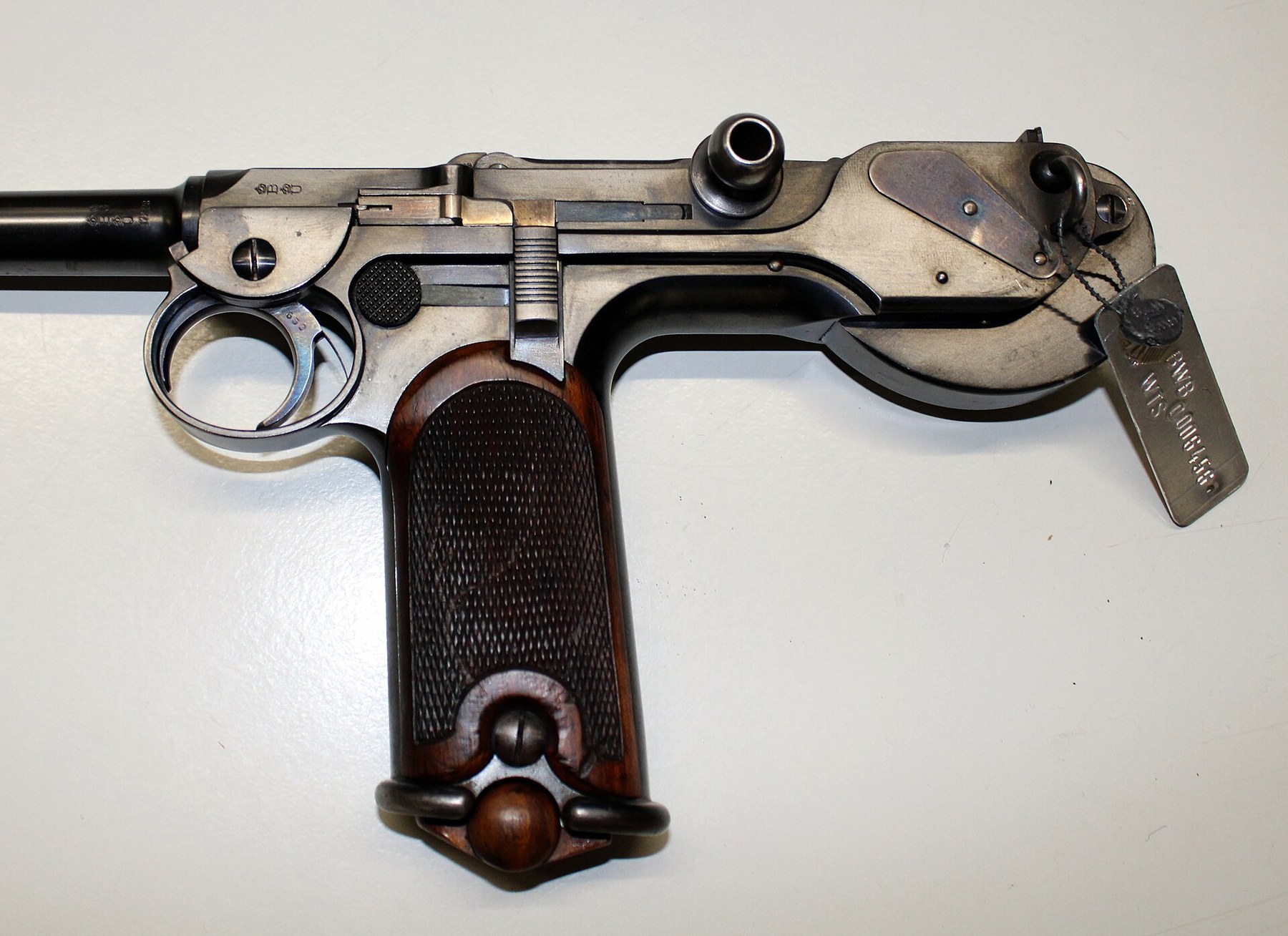
“The ejector is pivoted to the grip and raised by means of a small spiral spring.”1 It is part 14, with spring 15 and pin 16, and it is mounted on the stationary grip, not on the moving receiver; as the breechblock nears the end of its rearward travel the ejector rises through the slot in the block’s underside and strikes the case from below. The ejector has a practical consequence for reassembly, set out in Volume 6: its rear end has to be lifted with a screwdriver through the spring box opening so that the breechblock can pass over it.3
4.10 Trigger, sear and the yielding pin
The C-93’s trigger is on the stationary grip and its sear is on the moving receiver. That arrangement is the source both of its cleverest detail and of a legal point for anyone making one today.
“The trigger 10 moves in a circular groove on the side and forward of the grip, by pulling it the wedge-shaped end presses the front arm of the sear inward and raises the nose of the rear arm sufficiently to release the firing-bolt.”1
Borchardt’s patent explains why the trigger guard is offset: “Because of the one-sided position of the arm q’ the triggers and trigger-guard have been placed to one side”.6 The trigger’s arm, the “horn” of the ONI description, runs in an arc-shaped groove on the left of the grip and bears on the sear.
The problem the designer had to solve was that the action cycles faster than a finger. The Loewe manual:
“These movements are so rapid, that the eye cannot follow them, and the finger which has pulled the trigger has not the time to release it, before the parts would again be in position for firing; in order now that the sear may not strike solid against the still raised wedge-shaped end of the trigger a yielding pin 39 is fitted into the forward arm of the sear. This pin rests upon the small spiral spring 40 and recedes when it strikes against the trigger, and after the trigger has been released, snaps forward behind the wedgeshaped end of the latter, so that the firing can be repeated.”1
The yielding pin is the C-93’s disconnector. When the barrel and receiver return to battery with the trigger still held back, the pin in the sear meets the trigger’s wedge, yields into its socket and so does not trip the sear; only when the trigger is released does the pin spring forward behind the wedge, ready for the next pull. Scientific American called it “a special contrivance to prevent the whole eight cartridges being fired off in a second or so”.5 Borchardt’s patent says it prevents the pistol from “immediately fir[ing] itself without control of the operator”.6
That sentence is the reason the disconnector matters beyond history. A pistol that fires more than one shot for a single pull of the trigger is, in United States law, a machine gun. Volume 9 returns to this for anyone making a C-93-pattern pistol: the yielding pin and its spring are not details to approximate.
The ONI’s description adds a second safety function to the safety slide’s: the part numbered 7 is “a safety device for locking the sear; it also prevents any rearward movement of the barrel.”4
4.11 The safety
“The spring 8 which operates the magazine-holder also serves to secure the safety 7 in both positions. The safety is fitted into vertical grooves on the side of the grip. When pushed upward it locks the sear and trigger and prevents every motion of the mechanism. When the arm is not secured and ready for firing the top of the safety will stand flush with the edge of the receiver guides on the grip.”1
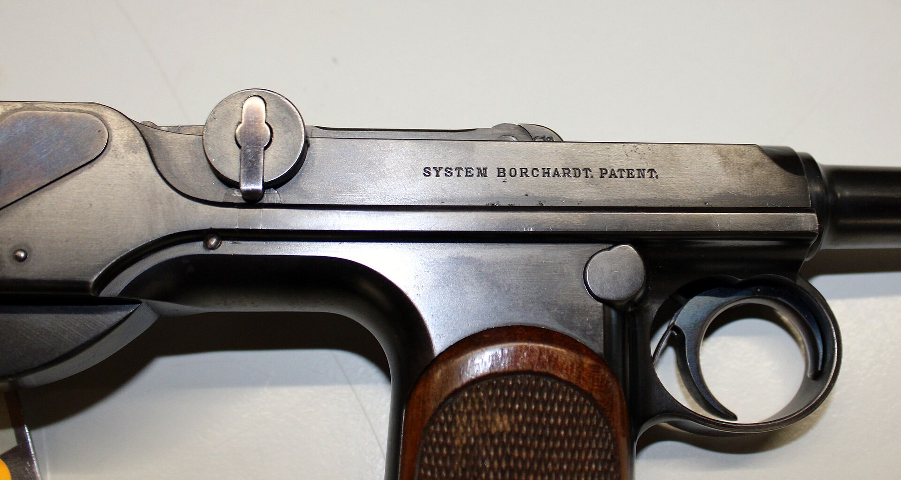
The safety is a vertical slide on the left of the grip, worked by the right thumb: up is safe, down is fire. Borchardt’s patent places it in “a corresponding groove milled in the left-hand outer side of the frame” and says it is “conveniently operated by the thumb of the right hand”; when up it blocks the sear, holds the trigger, and makes “the barrel b with its slides h … immovable”.6 The DWM manual adds: “The safety locks the sear directly over the cocking notch”, and “The loaded magazine can be inserted and withdrawn, while the mechanism is locked by the safety.”3 The single spring 8 that serves both the safety and the magazine catch is an economy typical of the design.
The Loewe manual’s warning about it is blunt: “The repeating pistol will always remain loaded and cocked when not all the cartridges are fired out of the magazine and barrel-chamber, it is therefore of the utmost importance either to unload the arm or to secure it by pushing up the safety, whenever the firing is discontinued.”1
4.12 The magazine and its catch
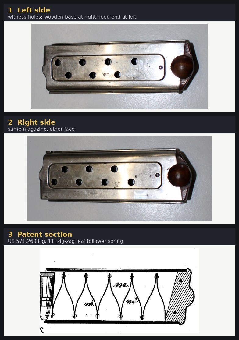
“The cartridges are contained in a sheet metal magazine-box 61–67 which is secured by the selfacting magazine holder 9. They are pressed upward by means of a zigzag-spring 68–71 and are arrested at the top by overhanging lips at the rear upper end of the magazine-box. This end is rounded out sufficiently so that the breech-block can push the uppermost cartridge out of the overhanging lips into the chamber of the barrel.”1
The magazine holds eight rounds. Its body is built up from two side plates (61, 62) and front and rear ribs (63, 64), with a wooden bottom piece (65) held by two pins; its spring is a stack of eight zig-zag leaves on a bottom leaf, joined by nine rivets, under a top plate (68–71).1 Auction descriptions give the body a nickel finish and the base walnut or hardwood, numbered to the pistol on Loewe guns.10 The side holes let the shooter count the remaining rounds; the DWM manual counts that among the pistol’s advantages and adds that the box magazine “permits the use of greased ammunition”.3
The catch, magazine holder 9, is pushed in from the left side by the right thumb. “Press upon the magazine holder with the thumb of the right hand and pull the magazine out of the pistol grip with the left.”3 Borchardt’s patent describes the spring snap and the “side knobs” by which the magazine is drawn down.6
4.13 No hold-open
The C-93 has no mechanism to hold its breech open on an empty magazine, and its factory said so in practice. Neither manual describes a hold-open, and both tell the owner to hold the breech open with a block of wood: “Remove the magazine and replace it by the wooden barring block, open the breech fully and push the bar up in front of the breechblock, the latter will now rest against the bar and is held back, while the barrel is being cleaned.”3 The Loewe manual calls it “a wooden bar”; the DWM list calls it “Barring block with jointed cleaning rod and oilbox”.13 The barring block is the size and shape of a magazine and doubles as a holder for the oil bottle and cleaning rod; Volume 5 shows one.
No source states in so many words that the pistol has no hold-open; the conclusion rests on the absence of any description of one and on the supplied block. Luger’s patent, by contrast, claims “a novel automatic arresting arrangement for keeping the breech open after the contents of the magazine have been exhausted”.7
4.14 Sights
The front sight is soldered to the barrel: “2 front sight, one piece, the sight is soldered on.”1 The rear sight is on the grip, at the top of the curved butt piece, which is why the distance between the sights is a long 315 mm: “The sight v is mounted upon the top of the thrust-piece a’ of the frame.”63
Whether the rear sight is adjustable varies between examples. A Bonhams description of Loewe serial 881 gives “express fore-sight, adjustable open rear-sight”; a Rock Island description of late DWM serial 1723 lists a “fixed integral rear sight” and a one-piece integral front sight “with the more pointed blade” among its late-production features.1112 Volume 5 treats this as a production change.

4.15 The stock attachment
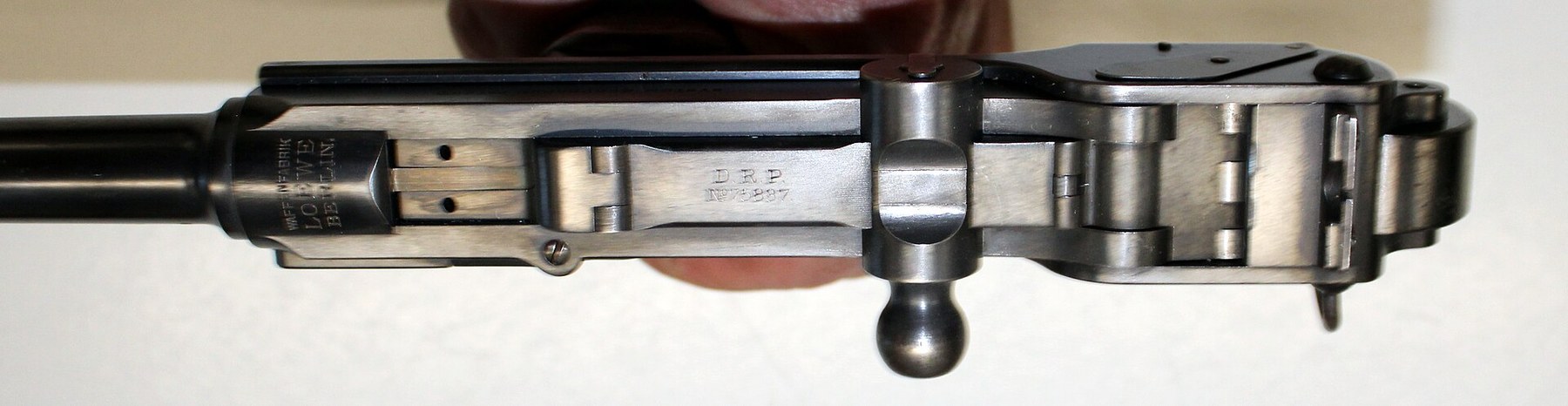
The detachable stock fixes to the back of the spring box, which is the strongest point on the rear of the pistol. “Insert the small tenon at the back of the spring-box into the slot of the small end of stock and turn the projecting roughed nut until the pistol is firmly seated.”3 The DWM parts list gives the stock as four items: “27. Wooden stock with ferrule and pin. 28. Connecting bolt with nut. 29. Connecting bolt pin. 30. Strap staple with screw.”3 The manual claims that “the attaching of the buttstock to the pistol requires but a few seconds”, and that with it “a target-range of 500 meters is obtained with a penetration of from 5 to 6 centimeters of pine.”3 Volume 7 sets that claim beside the ONI’s ballistic data.
4.16 What the factory claimed for the mechanism
The DWM manual’s “Properties and advantages” are a useful summary of what the factory thought it had built, and are quoted here as claims:3
- “It is absolutely safe, its parts are comparatively stronger than those of modern military rifles.”
- “The loading and unloading, locking and unlocking of the safety is performed, while retaining the pistol in the right hand.”
- “The recoil is greatly reduced, being counteracted and distributed by springs.”
- “The automatic functions of loading the chamber and closing the breech are performed with absolute certainty by means of the toggle-joint mechanism. The latter seems especially adapted for automatic firearms, inasmuch as the last straightening of the toggles exerts an infinite power in closing the breech.”
- “The mechanism does not foul, because the breech is not opened before the bullet has left the barrel, and before the propelling gases have lost their pressure upon the breech.”
- “An excellent precision in shooting is attained by the long distance between sights (315 mm) and the uniform resistance to the recoil.”
The claim about the toggle’s “infinite power” in closing is the mechanical point behind the design: as a toggle approaches straight, a small force along the spring produces a very large force along the links, so the last few millimetres of the breechblock’s travel seat the cartridge hard. It is the same reason a toggle clamp holds. The claim about recoil is the one later users disputed (Volume 7).
4.17 What could not be established
- The barrel’s travel, given only once, by the ONI, as 0.118 inch; and the meaning of the ONI’s companion figure of 0.373 inch.
- Whether the closed toggle sits on centre or below it. Not stated in the patent or the manuals.
- Parts 20 to 22, 25 and 60, which the transcribed parts list does not name individually.
- Part 45, whose name on the scanned list is read as “firing bolt spring reinforce” with low confidence.
- The overall length, given with a source only on a museum label.
References
Footnotes
-
Ludw. Loewe & Co., Actiengesellschaft, Repeating Pistol (System Borchardt), English edition (Berlin, Hollmann-Strasse 32; printed by H. S. Hermann, n.d., before 1897), “Description of the Repeating Pistol (System Borchardt)”, printed pp. 3–7; parts list pp. 11–13; specifications p. 14. Page images at https://landofborchardt.com/LoeweManual.html, consulted 2026-10-18; transcribed for this dive. ↩ ↩2 ↩3 ↩4 ↩5 ↩6 ↩7 ↩8 ↩9 ↩10 ↩11 ↩12 ↩13 ↩14 ↩15 ↩16 ↩17 ↩18 ↩19 ↩20 ↩21 ↩22 ↩23 ↩24 ↩25 ↩26
-
H. Borchardt, DRP 75,837, “Selbsttätige, besonders als Repetirpistole verwendbare Feuerwaffe”, patented 9 September 1893. OCR text at https://patents.google.com/patent/DE75837C/de, consulted 2026-10-18; drawing sheets from the DPMA register PDF, https://register.dpma.de/DPMAregister/pat/PatSchrifteneinsicht?docId=DE75837C, downloaded 2026-10-18. ↩ ↩2 ↩3
-
Deutsche Waffen- und Munitionsfabriken, Automatic Repeating Pistol, Borchardt Patent, English edition (Berlin S.W., n.d.), pp. 4–13 and Plates I–III. Scan circulated by Forgotten Weapons, https://www.forgottenweapons.com/wp-content/uploads/2013/10/Borchardt-C93-Manual-English.pdf, and page images at https://landofborchardt.com/C93manual.html, consulted 2026-10-18. ↩ ↩2 ↩3 ↩4 ↩5 ↩6 ↩7 ↩8 ↩9 ↩10 ↩11 ↩12 ↩13 ↩14 ↩15 ↩16 ↩17 ↩18 ↩19 ↩20 ↩21 ↩22 ↩23
-
US Office of Naval Intelligence, General Information Series No. XV (July 1896), “Notes on Small Arms”, pp. 129–131 and plate. Internet Archive
generalinformati3533unit, consulted 2026-10-18. ↩ ↩2 ↩3 -
“Improved Repeating Pistol”, Scientific American vol. 73 no. 5, 3 August 1895, p. 69. Internet Archive
scientific-american-1895-08-03, consulted 2026-10-18. ↩ ↩2 -
Hugo Borchardt, US Patent 571,260, “Recoil Magazine-Pistol”, filed 21 October 1893, patented 10 November 1896, specification and Figs. 1–12. https://patents.google.com/patent/US571260A/en, consulted 2026-10-18. ↩ ↩2 ↩3 ↩4 ↩5 ↩6 ↩7 ↩8 ↩9
-
Georg Luger, US Patent 753,414, “Recoil-loading small-arms”, filed 17 March 1900, patented 1 March 1904. https://patents.google.com/patent/US753414A/en, consulted 2026-10-18. ↩ ↩2 ↩3
-
Wehrtechnische Studiensammlung Koblenz, museum label, photographed as File:Pistole C 93 System Borchardt Tafel in der WTS-Koblenz.jpg, CC BY-SA 4.0, consulted 2026-10-18. ↩
-
“Luger pistol”, English Wikipedia, https://en.wikipedia.org/wiki/Luger_pistol, consulted 2026-10-18. ↩
-
Rock Island Auction Company, lot 75-2694, “Loewe 1893 Borchardt pistol with matching stock”, https://www.rockislandauction.com/detail/75/2694/loewe-1893-borchardt-pistol-with-matching-stock, consulted 2026-10-18. ↩
-
Bonhams, Modern Sporting Guns, London, 28 November 2019, sale 25427, lot 42, https://www.bonhams.com/auction/25427/lot/42/, consulted 2026-10-18. ↩
-
Rock Island Auction Company, lot 69-3297, DWM serial 1723, consulted 2026-10-18. ↩
Comments (0)