MG 42 · Volume 3
How It Works: Two Rollers, a Gas Trap and a Two-Stroke Feed
The parts and their names, the cycle of operation from the 1943 US analysis, the muzzle booster, the firing-pin interlock, the belt feed, trigger and safety, and why the MG 42 is roller-locked while the G3 is only roller-delayed
3.1 Sources for this volume
No German description of the MG 42’s mechanism was available for this dive (Volume 6 lists the German manuals and why none was readable). The mechanism is therefore described from three documents that analysed captured guns and one maker’s manual for the direct descendant:
- the US War Department’s Tactical and Technical Trends No. 31 of 12 August 1943, which published a drawing of the lock and a paragraph-by-paragraph explanation of it;1
- the Military Intelligence Service’s German Infantry Weapons of May 1943;2
- George M. Chinn’s The Machine Gun, volume I (1951);3
- Rheinmetall’s English-language Machine Gun MG3 Operator’s Manual (1992), for the names of the parts in a gun whose lock, bolt and feed are the MG 42’s, re-chambered for 7.62×51 mm.4
Where these differ, the difference is stated. The sources describe the same mechanism in different words; this volume quotes them rather than paraphrasing their technical claims.
3.2 The names of the parts
Rheinmetall’s MG 3 manual names the bolt’s parts as bolt head, locking roll (two), firing pin, firing pin holder, ejector, ejector rod, bolt housing and bolt catch.4 The 1943 American documents call the same parts the bolt head, rollers or “locking studs”, the firing-pin holder and the bolt carrier.12 This dive uses bolt head, rollers, firing-pin holder and bolt carrier, with the MG 3 names where Volume 6 follows that manual.
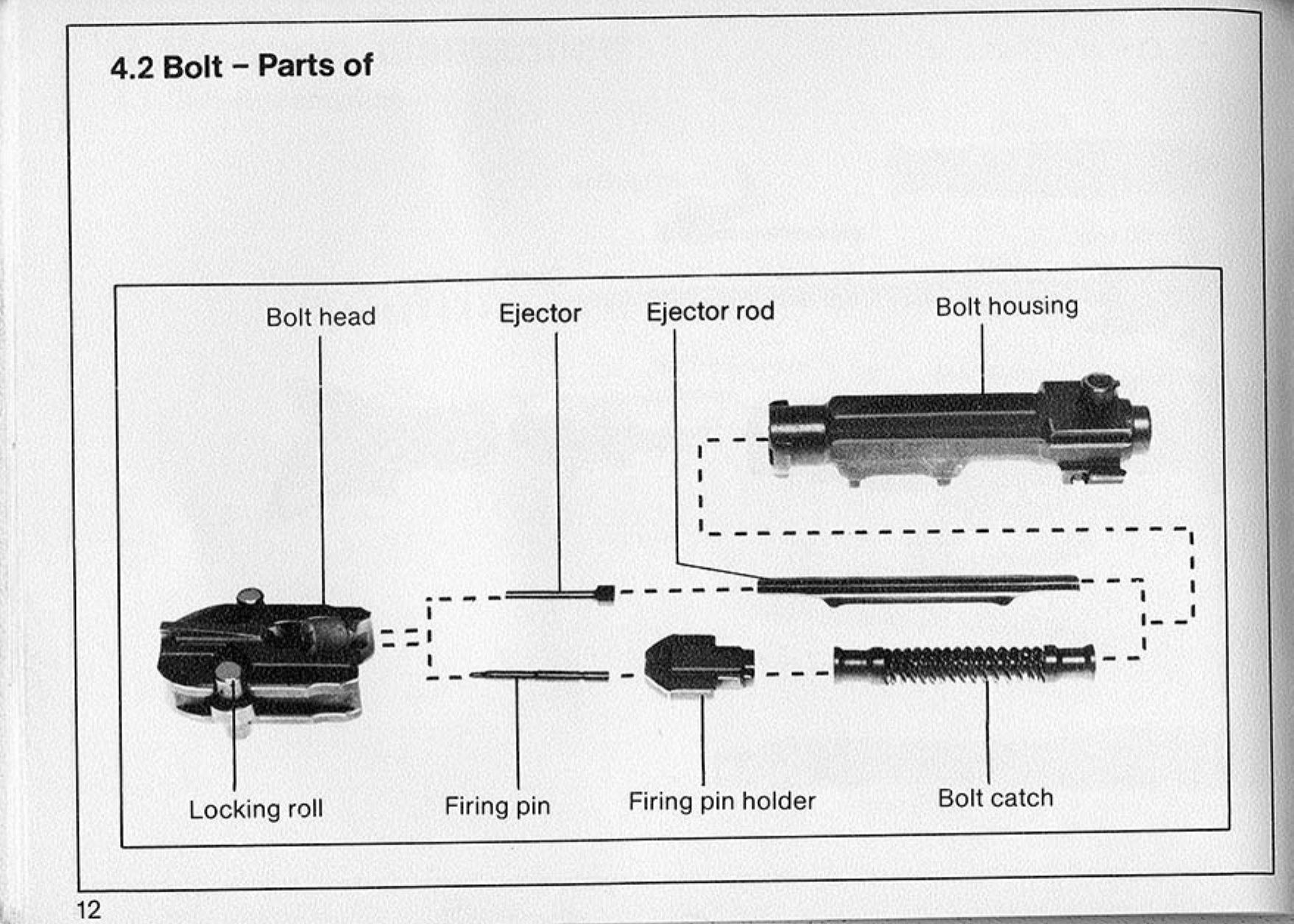
The other major groups, again in the MG 3 manual’s words, are the barrel, the recoil booster (the muzzle device), the barrel guide sleeve, the receiver, the cover with its feed tray, the cocking slide, and the butt with rear cover and recoil spring.4 The wartime handbook labels the feed parts feed arm, feed pawls, cartridge stop and feed-plate lower assembly, and the bolt-mounted roller that drives the feed arm the feed-arm operating stud.2
3.3 Characteristics
The War Department published this table in August 1943 from captured guns:1
Table 1 — Characteristics
| Item | TTT No. 31 (Aug 1943) |
|---|---|
| Weight with bipod | 23¾ lb |
| Length overall | 48 in |
| Length of barrel | 21¾ in |
| Weight of barrel | 3 lb 14¼ oz |
| Cyclic rate of fire | 1,100–1,350 rpm |
| Mounting | bipod or tripod |
| Calibre | 7.92 mm (.311 in) |
| “There is no provision for single shots.” |
The May 1943 handbook gave the light-gun weight as 25½ lb, and the Munster museum placard (Volume 2) gives 11.6 kg with bipod and 1,230 mm overall.2 These are not reconciled here; a gun’s weight depends on its butt, bipod and which barrel is fitted, and the sources do not say what each weighed. The rate of fire has its own volume (Volume 4).
3.4 The cycle, step by step
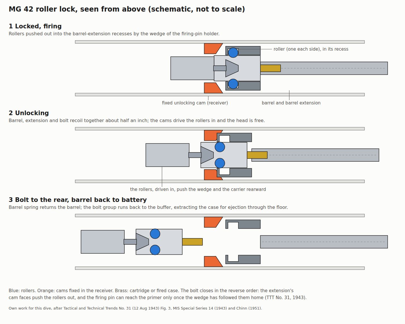
The MG 42 is a short-recoil gun: the barrel moves. Its rollers turn on axles set at right angles to the bore, “symmetrically in slots in the sides of the bolt head with their axles vertical,” as the 1943 handbook puts it, so they move sideways, in and out of the bolt head.2 The handbook’s image for them is a wheelbarrow: “These locking studs resemble a wheelbarrow wheel and axle.”2
1. Ready to fire. The gun fires from an open bolt. When it is cocked the bolt is held to the rear by the sear, which Chinn describes as engaging “its locking notch in the bottom of the bolt”.3
2. Feeding and chambering. Pressing the trigger releases the bolt. “As the bolt is thrust forward by the compressed driving spring, the bolt face knocks the cartridge out of its link ahead of the counterrecoiling parts into the chamber.”3 The MG 42’s belt is a push-through belt: the cartridge is pushed forward out of the link, not drawn backwards.
3. Locking. The bolt head stops against the breech. The carrier, still moving, drives the firing-pin holder’s wedge forward between the rollers. The War Department’s description: “On the return of the bolt, the impact of the roller with the camming surfaces I … on the barrel extension carry the rollers from their seats, and, together with surfaces J on the bolt head, force the rollers outward locking the bolt head to the barrel extension.”1 The rollers now sit partly in the bolt head and partly in recesses in the barrel extension, and the head cannot move relative to the barrel.
4. Firing. Only when the rollers are fully out can the firing pin reach the primer (see the firing-pin interlock). Chinn: “the firing pin, which is now an integral part of the rear portion of the bolt, is driven forward by inertia and detonates the primer.”3
5. Locked recoil. “On firing, the barrel extension and the bolt recoil together a half inch.”2 Chinn gives the same distance: “both pieces traveling rearwards as a unit until a distance of one half inch is reached.”3 During this travel the bullet leaves the barrel and the propellant gas acts on the muzzle booster, pushing the barrel back harder (below).
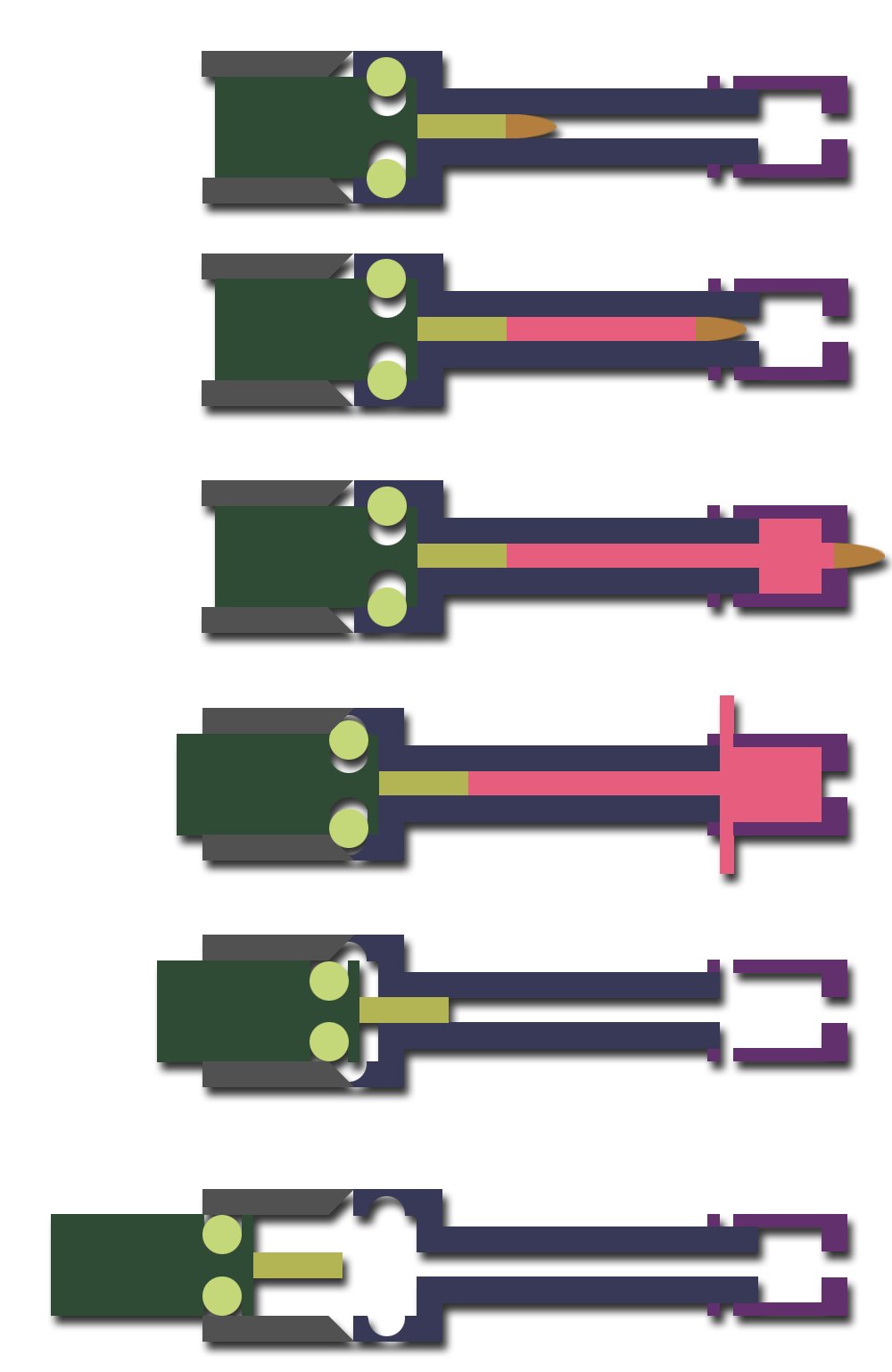
6. Unlocking. At the end of that half inch, the rollers meet cams fixed in the receiver. The War Department: “On firing barrel A and barrel extension B recoil to the rear until rollers C are cammed inward by fixed cams D unlocking bolt head E and retracting firing pin F.”1 Driven inward, the rollers bear on the wedge in front of the carrier; on this reading of the 1943 drawing they push the carrier rearward as the head is freed, which is why one modern diagram (below) calls the system “roller-accelerated”. The US sources describe the camming, not the acceleration.
7. Separation. “Then travel of the barrel and its extension is stopped … The bolt is thus freed to continue to the rear, accelerated by the impact of the high residual pressure in the bore on the face of the bolt, while the barrel-return spring pushes the barrel and extension back to battery.”3 The War Department: “The bolt carrier G and bolt-head continue to the rear guided by fixed guides H while barrel and barrel extension return to battery.”1
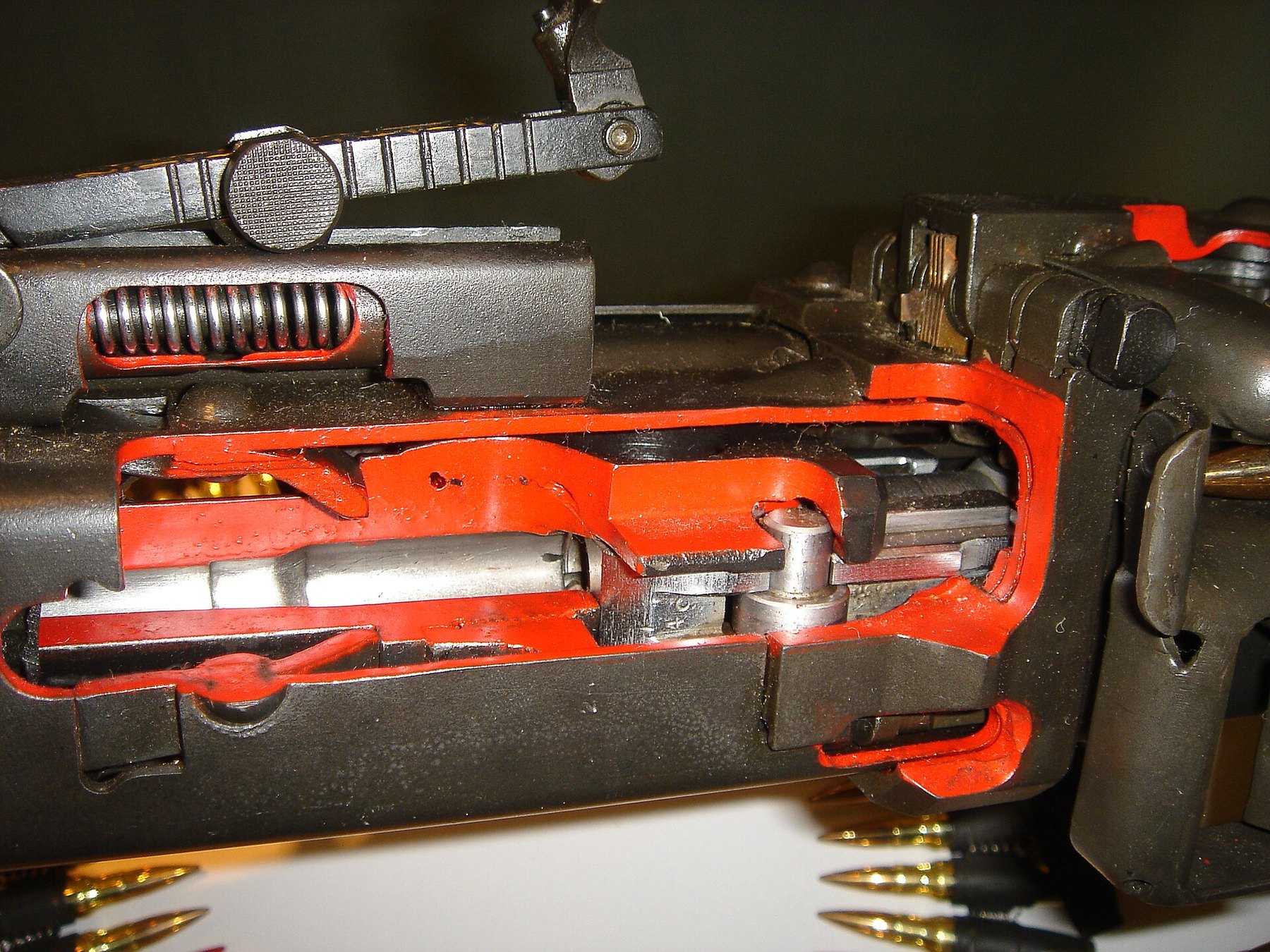
8. Extraction, ejection and feed. The extractor carries the case back until the ejector knocks it downward through the receiver floor. “The first movement of the bolt in recoil levers the next round in the belt into position and places the feed pawl behind the next cartridge.”3
9. Buffer and return. The bolt runs back until it “strikes the strong helical spring located in the shoulder stock”, and the buffer and driving spring together “start the operating parts back into counterrecoil to repeat the cycle”.3 If the trigger is still held, the cycle repeats; if not, the sear catches the bolt in its notch.
3.5 Locked, not delayed
The MG 42’s lock is easy to confuse with the roller system of the G3 and its relatives, because both put two rollers in the sides of a bolt head. They work on opposite principles.
- In the MG 42, the rollers lock. The bolt head is held to the barrel extension, and nothing moves between them until the whole assembly has recoiled and fixed cams in the receiver have driven the rollers in. The gun is recoil-operated: the barrel’s movement is what unlocks it.13
- In the G3 family, the barrel is fixed and the rollers only delay. From the moment of firing, the case pushes the head back, the rollers are forced inward against angled faces in the trunnion, and that inward movement drives the carrier back faster than the head, slowing the head down. It is a form of blowback. The hub’s H&K PSG1 dive, Volume 3, explains that cycle and its 1:4 ratio in detail.
The bridge between them is Mauser’s wartime work at Oberndorf, which tried a roller-locked rifle and arrived at the roller-delayed StG 45(M). Volume 7 gives that line in outline and links onward.
3.6 The muzzle booster
The MG 42 adds energy to its recoiling parts with a muzzle booster (Rückstoßverstärker, which Rheinmetall’s English manual translates as “recoil booster”). Chinn’s description is of the MG 42’s device:
“This simple device, fastened to the forward end of the barrel jacket, not only trapped the still expanding gases after the bullet left the bore, but it also served as a front barrel bearing and flash suppressor. It was so slotted that the escaping gas, after it had been reworked, hit against angled buffers to serve as a muzzle brake for stabilizing the weapon during a short burst at an abnormally high cyclic rate.”3
In his account of the MG 34 he gives the principle in one sentence: the booster “held the high gas pressure after the bullet had cleared, but made it do double work by bringing it to bear on the barrel face for additional rearward thrust of the recoiling parts.”5 The gas pushes on the front of the barrel, and the barrel, still locked to the bolt, is driven back harder and faster than recoil alone would drive it.
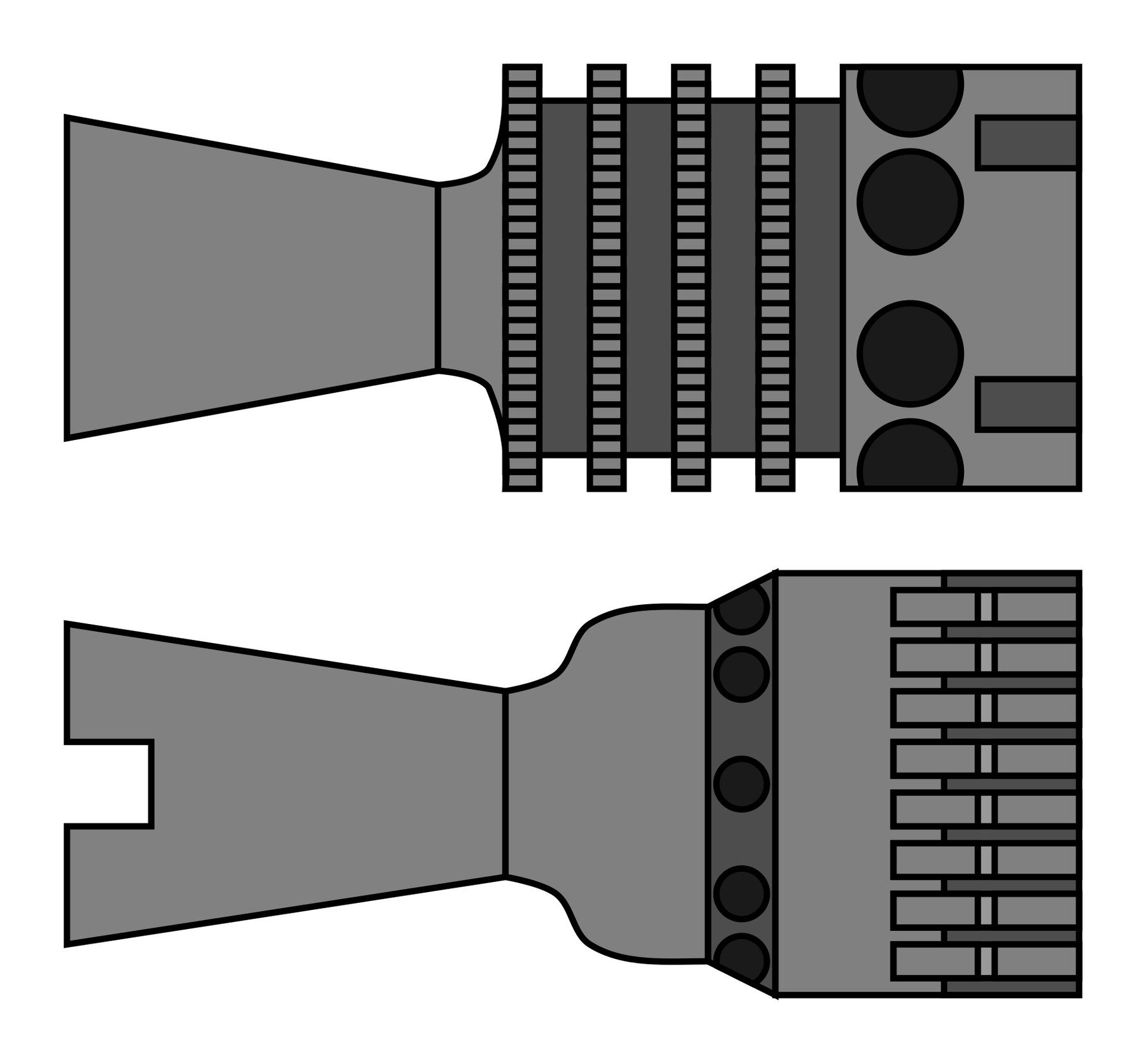
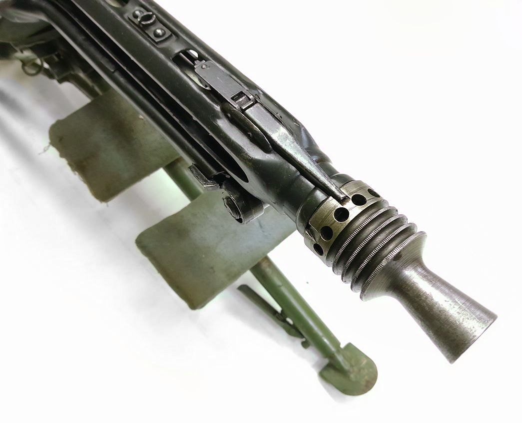
Because the booster is the front bearing of the barrel, it is also part of the barrel change: the barrel’s muzzle seats in it and its rear swings out of the jacket (Volume 4). The MG 3 booster is removed by lifting a catch and unscrewing it; the barrel guide sleeve behind it comes out next.4
3.7 The firing-pin interlock
The MG 42 cannot fire before it is locked, and the reason is in the same part that locks it. The War Department, 1943:
“The initial outward motion of the rollers also frees the firing pin holder K which is driven forward by spring pressure insuring complete locking (by wedging rollers outward) before the firing pin can strike the primer.”1
The firing pin is carried by the holder whose front is the wedge. The wedge can move forward only as far as the rollers let it, and the rollers can move out only when the bolt head is in the barrel extension, opposite the recesses. A bolt that has not closed fully cannot let the wedge, and the pin with it, go home. Unlocking does the reverse: “the rollers C are cammed inward … unlocking bolt head E and retracting firing pin F.”1
3.8 The feed: a belt moved in two steps
The MG 42 feeds from the left from a non-disintegrating, push-through metallic belt. The May 1943 handbook: belts of “50 rounds and may be connected to make longer belts”; the belt is inserted “with the open end of the links down” and pulled through “until the first round can be engaged by the feed pawls (a three-cartridge width)”.2 Rheinmetall’s 1992 trouble-shooting table, for the MG 3’s belts, says to “load ammunition belt with belt links upwards”.4 The two descriptions are of different belts and different wording (“open end down” and “links upwards” may well describe the same orientation of a looped link), and are quoted, not reconciled.
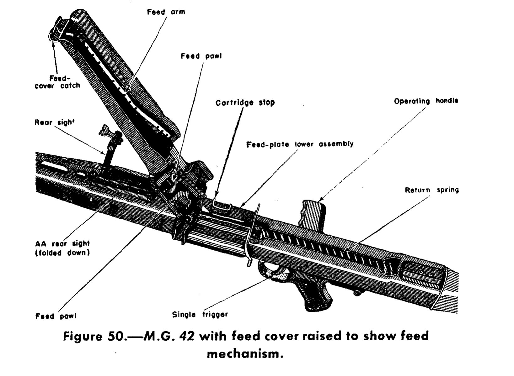
The novelty is in how the belt is moved. As in the MG 34, a feed arm in the cover is swung by a stud on the bolt. In the MG 42, the War Department found:
“two feed pawls are linked to the front end of the arm by an intermediate link, in such a way that when one is feeding, the other is riding over the next round in the belt. The effect of this is that feed is in two steps instead of one step as in the MG 34, and is therefore much smoother.”1
Chinn’s version: “Two feed pawls were linked to the front end of the arm by an intermediate link in such a way that when one was chambered, the other was being positioned behind the next round in the belt. Loading was thus performed in two stages instead of one continuous movement. This made lurching of the belt less violent and did not impede the gunner’s aim.”3
Both sources draw the same conclusion: spreading the belt’s movement over two stages instead of one makes it smoother, which matters at the MG 42’s rate of fire with a long belt hanging from the gun. The feed’s influence outlasted the gun: the US Ordnance Corps took “the feed system of … the MG 42” for its postwar T44 machine gun.6
For mobile use, the belt could be carried in a drum. The handbook: a 50-round belt “contained in a metal drum attached to the feedblock”, hooked to a lug at the front of the feed and latched at the rear; and “a special feed cover to take a 75-round saddle-type drum” for which “no belt is used”.2 Chinn says only that “a few have been known to be modified to take a saddle drum feed that held 75 belted cartridges”, which contradicts the handbook on whether the saddle drum held a belt.3
3.9 Trigger, sear and safety
The MG 42 has a single trigger and fires only automatically. Every source read agrees: “There is no provision for single shots”;1 the trigger “is not equipped with two triggers as in the M.G. 34, and the gun cannot fire semi-automatically”;2 the selector’s “only two settings … being for Safe and for Automatic fire”.3 (One paragraph of the 1943 handbook, on the 75-round drum, tells the gunner to “use the trigger for semi- or full-automatic fire”; it contradicts the same handbook’s identification list and every other source, and is treated here as a drafting error.)2
The safety is a push-button through the grip housing. The handbook: “There is a plunger-type safety catch located just above the pistol grip … it works from side to side. The safety catch cannot be operated unless the gun is cocked. To put the gun on ‘safe,’ push the safety catch toward the left (facing the muzzle), until the letter ‘S’ (sicher — ‘safe’) shows on its surface. To put the gun on ‘fire,’ push the safety catch toward the right until the letter ‘F’ (Feuer — ‘fire’) is exposed.”2
Because the gun fires from an open bolt, “safe” locks the trigger against a bolt that is already held back. The handbook’s instruction after cocking is to push the operating handle forward again “until a ‘click’ is heard”, because the handle is separate from the bolt and is not carried in the cycle; the MG 3 manual gives the same step as “retract cocking slide and push forward”.24
3.10 Extraction, ejection and the ejection-port cover
Cases leave through the bottom of the receiver.3 A spring-loaded cover closes the ejection opening against dirt: “The ejection-port cover will open automatically whenever the trigger is pulled back,” and the handbook tells the gunner to keep it closed whenever the gun is not firing.2 Chinn: it “flies open the instant the trigger is pulled back. When firing has been interrupted for any length of time, this piece is snapped shut by hand.”3
3.11 Recoil spring and buffer
The recoil (return) spring sits in the buffer housing behind the receiver, and the butt fits over it. The May 1943 handbook warns that removing the buffer housing releases “the large recoil, or return, spring”, which must be held under control; the Aberdeen comparison calls the arrangement a “simplified buffer mechanism with a very heavy spring”.27 Rheinmetall’s MG 3 manual describes removing the butt “together with rear cover and recoil spring” and adds the warning “Spring is still compressed!”4 Volume 6 gives the strip order.
The bolt’s weight is one of the variables that sets the rate of fire, and it is the variable the MG 42’s descendants changed. Ian McCollum gives the MG 42’s bolt as 550 g (1.2 lb), against 950 g (2.1 lb) for the heavy bolt Rheinmetall made for the MG 42/59, which brought the rate down to 700 to 900 rounds a minute.8 Volume 4 takes up the rate in full.
3.12 What could not be established
- A German description of the mechanism, in the original terms, from the wartime manuals (D 166/1, Merkblatt 41/18, H.Dv. 241, H.Dv. 181/7). None was found as a readable scan.
- The roller and cam geometry: the locked-recoil distance is given only as “a half inch” by two US sources; no cam angle, roller diameter or headspace figure was found for the MG 42.
- Whether the 75-round saddle drum held a belt (the handbook says not; Chinn implies it did).
- Wartime German figures for bolt weight. The 550 g figure is McCollum’s, given for the purpose of comparing the MG 42/59.
References
Footnotes
-
US War Department, Military Intelligence Service, Tactical and Technical Trends No. 31 (12 August 1943), item 16, “More Details of the German MG 42”, pp. 37–39, with figures 1–3. Internet Archive, https://archive.org/details/TacticalAndTechnicalTrendsNos31-40 ; Lone Sentry transcription, https://www.lonesentry.com/articles/ttt/mg42.html , consulted 2026-10-19. ↩ ↩2 ↩3 ↩4 ↩5 ↩6 ↩7 ↩8 ↩9 ↩10 ↩11
-
US War Department, Military Intelligence Service, German Infantry Weapons, Special Series No. 14 (25 May 1943), section 13, “M.G. 42”, pp. 83–94, figures 49–51. Internet Archive, https://archive.org/details/German_Infantry_Weapons_1943_MIS_Special_Series_No._14 , consulted 2026-10-19. ↩ ↩2 ↩3 ↩4 ↩5 ↩6 ↩7 ↩8 ↩9 ↩10 ↩11 ↩12 ↩13 ↩14 ↩15
-
George M. Chinn, The Machine Gun, vol. I (Washington: Bureau of Ordnance, Department of the Navy, 1951), chapter 33, “MG-42 Machine Gun”, pp. 484–489. Internet Archive, https://archive.org/details/TheMachineGunVolume1ByGeorgeMChinn , consulted 2026-10-19. ↩ ↩2 ↩3 ↩4 ↩5 ↩6 ↩7 ↩8 ↩9 ↩10 ↩11 ↩12 ↩13 ↩14 ↩15
-
Rheinmetall International S.A. (Brussels), Machine Gun MG3 Operator’s Manual, Cal. 7.62 mm x 51 (printed in the Federal Republic of Germany, 1992), pp. 6–7, 10–12, 21–30, 42. Internet Archive, https://archive.org/details/machine-gun-mg-3-operators-manual-1992 , consulted 2026-10-19. ↩ ↩2 ↩3 ↩4 ↩5 ↩6 ↩7
-
Chinn, The Machine Gun, vol. I (1951), the Mauser MG 34 section, pp. 473–477, same scan. ↩
-
Chinn, The Machine Gun, vol. III (1953), chapter 14, section 1. Internet Archive, https://archive.org/details/TheMachineGunVolume3ByGeorgeMChinn , consulted 2026-10-19. ↩
-
Tactical and Technical Trends No. 32 (August 1943), item 12, “Comparison of German Machine Guns”, pp. 36–37, same scan. ↩
-
Ian McCollum, “Rheinmetall MG42/59: The Slow-Fire Commercial MG42”, Forgotten Weapons, 4 May 2022, https://www.forgottenweapons.com/rheinmetall-mg42-59-the-slow-fire-commercial-mg42/ , consulted 2026-10-19. ↩
Comments (0)