FP-45 Liberator — Repros & DIY · Volume 7
Blueprints & Drawings

A builder needs dimensions, not descriptions, and the FP-45 is unusually well served: the actual 1942 Inland Manufacturing Division / General Motors factory drawings survive, in full, with real title blocks, material specs, tolerances, dates, and engineering-change tables. They are far better than any patent could be — and, as it happens, no patent exists (below). This volume walks the drawing set: where it lives, how it is organized, what each key sheet gives you, a dimension-reference table drawn strictly from the research, and how to translate 1942 drawings into modern CAD. It is the reference layer under Volume 6’s build.
7.1 No FP-45 Patent Exists — Say So
First, a correction to a natural assumption. There is no US patent covering the FP-45 Liberator. Extensive patent searching — Google Patents inventor/assignee searches for George Hyde, Inland Manufacturing, and Guide Lamp Division across 1942–45 — turned up nothing covering the Liberator pistol itself.1 George Hyde does hold other real firearm patents (a 1936 patent for the Hyde Model 35, predecessor to the M3 “Grease Gun,” and a WWII-era rifle patent, US 2,376,057), but those cover the Grease Gun and a rifle, not the Liberator — do not cite a Hyde patent as the Liberator’s.2 This absence is consistent with the FP-45 being a classified, deliberately obfuscated wartime government project (the cover-name scheme, below) that would have had no reason to run through peacetime patent prosecution. UNVERIFIED: no FP-45 patent was found; treat it as likely nonexistent rather than hunting a number that is not there. The factory drawings are the real, and better, source.
7.2 Where the Drawings Live
The drawing set was reproduced in Ralph Hagan’s 1996 book The Liberator Pistol: Development, Production, Distribution, and a scanned PDF of it is hosted, with Hagan’s permission per its own credit page, at:
- https://www.survivorlibrary.com/library/liberator_pistol_blueprints.pdf — read directly in research, ~20 pages.3
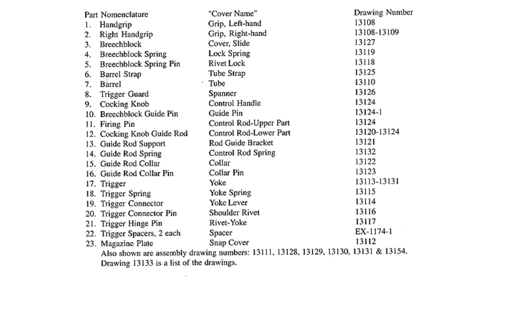
It opens with a courtesy/credit page (crediting Ralph Hagan and biggerhammer.net), then a part-nomenclature-to-drawing-number cross-reference table, then the individual dimensioned, toleranced factory drawings themselves — genuine GM/Inland title blocks, material specs, dates starting May 1942, and engineering-change tables. Use it directly, with credit to Hagan, rather than redrawing from scratch. Mirrors exist (Scribd copies) for redundancy against link rot, but the survivorlibrary PDF is the directly-verified source.4
Acquiring Hagan’s physical book is worth it if you want the full production narrative alongside the drawings; no live current retail link for the book itself was found in research (the PDF’s credit page cites a now-defunct purchase page).
7.3 How the Set Is Organized
The drawings are numbered 13108 through 13133+, with 13133 itself an index of the drawings. The set covers all ~23 numbered parts. The key organizing feature for a modern reader is the wartime cover-name scheme — the drawings use euphemisms to disguise what was being built, and you have to translate them:
Table 1 — The drawings are numbered 13108 through 13133+, with 13133 itself an index of the drawings. The set covers all ~23 numbered parts. The key organizing feature for a modern reader is the wartime cover-name scheme — the drawings use euphemisms to disguise what was being built, and you have to translate them
| Cover name on drawing | What it actually is |
|---|---|
| Tube | Barrel |
| Yoke | Trigger |
| Yoke Lever | The cam that acts as the sear |
| Control Rod | Firing pin / striker |
| Spanner | Trigger guard |
| Snap Cover | Magazine/grip door |
The full nomenclature-to-drawing-number cross-reference is on the parts-list page of the PDF.3 Read that page first; it is the map to everything else.
7.4 The Dimension Reference Table
The following is drawn strictly from the research’s reading of the drawings — it is illustrative, not exhaustive, and the full PDF has the complete set. Every value here is from the factory drawings as reported; pull the actual sheets before cutting metal, and mark anything you cannot confirm on the sheet as uncertain.
Table 2 — The Dimension Reference Table
| Part | Dwg # | Material / spec | Key dimensions |
|---|---|---|---|
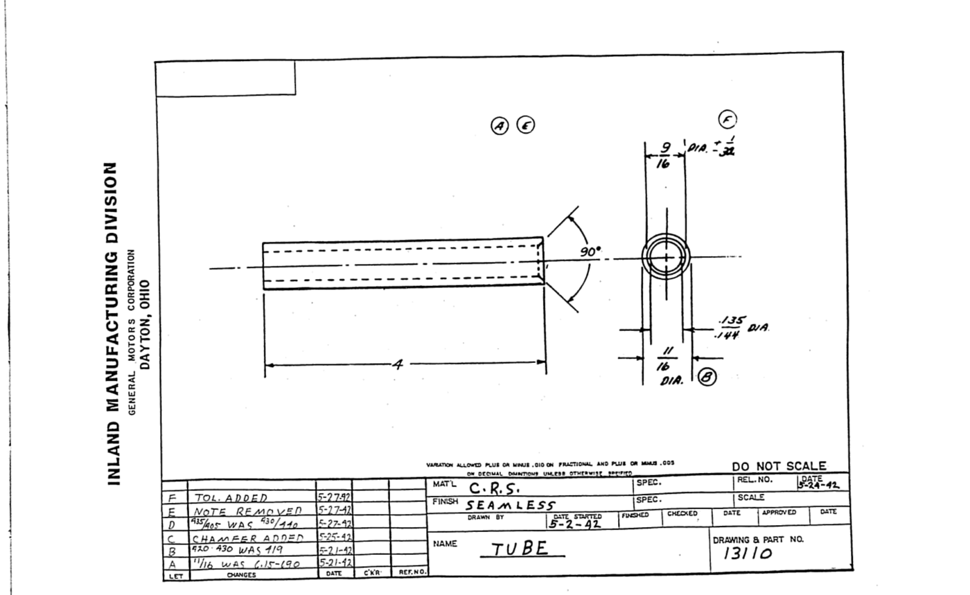
| Tube (barrel) | 13110 | C.R.S., seamless | 4″ long; stepped OD from 11/16″ dia. down to .135–.144″ dia. at muzzle; .0222″ included taper per inch over the taper |
| Tube & Strap Assembly | 13111 | C.R.S. | barrel OD ground to .4715–.4740″ over the strap-bearing section; arc-welded strap joint |
| Grip L.H./R.H. Assembly | 13108 / 13108–13109 | C.R.S. | projection-welded rivet-yoke and rivet-lock bosses |
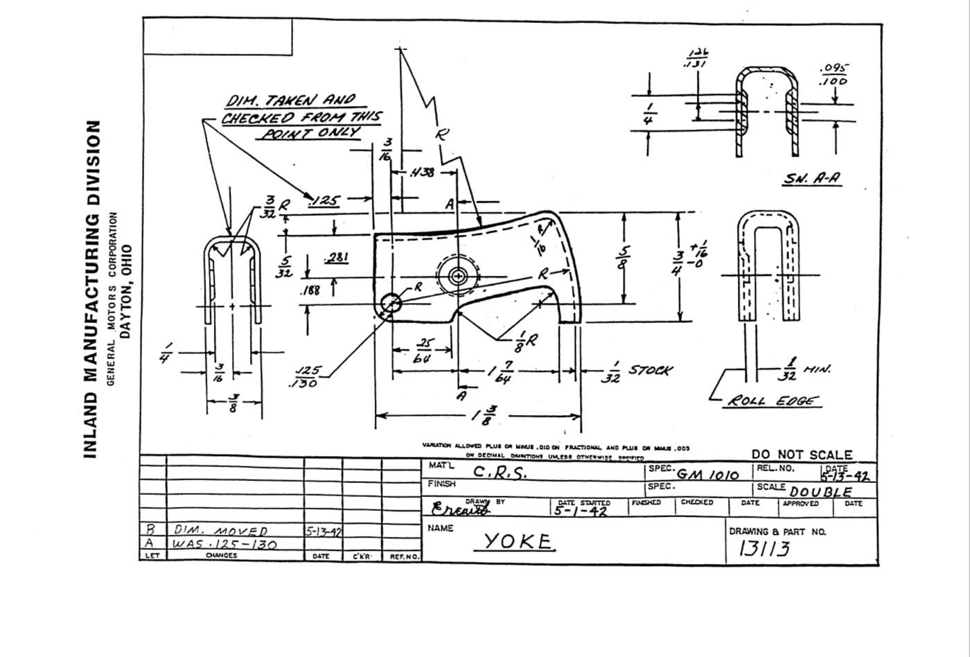
| Yoke (trigger) | 13113 | C.R.S., GM 1010 spec | pivot-hole .188/.281″ referenced dims; 1-3/8″ overall |
| Yoke Lever (“sear” cam) | 13114 | C.R.S., GM 1010, case .004–.008″ | cam profile from four blended radii (.032R / .075R / .150R / .125R) — a flat cam follower, not a hooked sear |
| Yoke Spring | 13115 | Music wire, stress-relieved | ~3/4″ arm; 20° working range; 2.5 lb max load; must not take permanent set |
| Lock Spring | 13119 | Music wire, stress-relieved | 6 coils, left-hand wound, over a 3/16″ dia. rod |
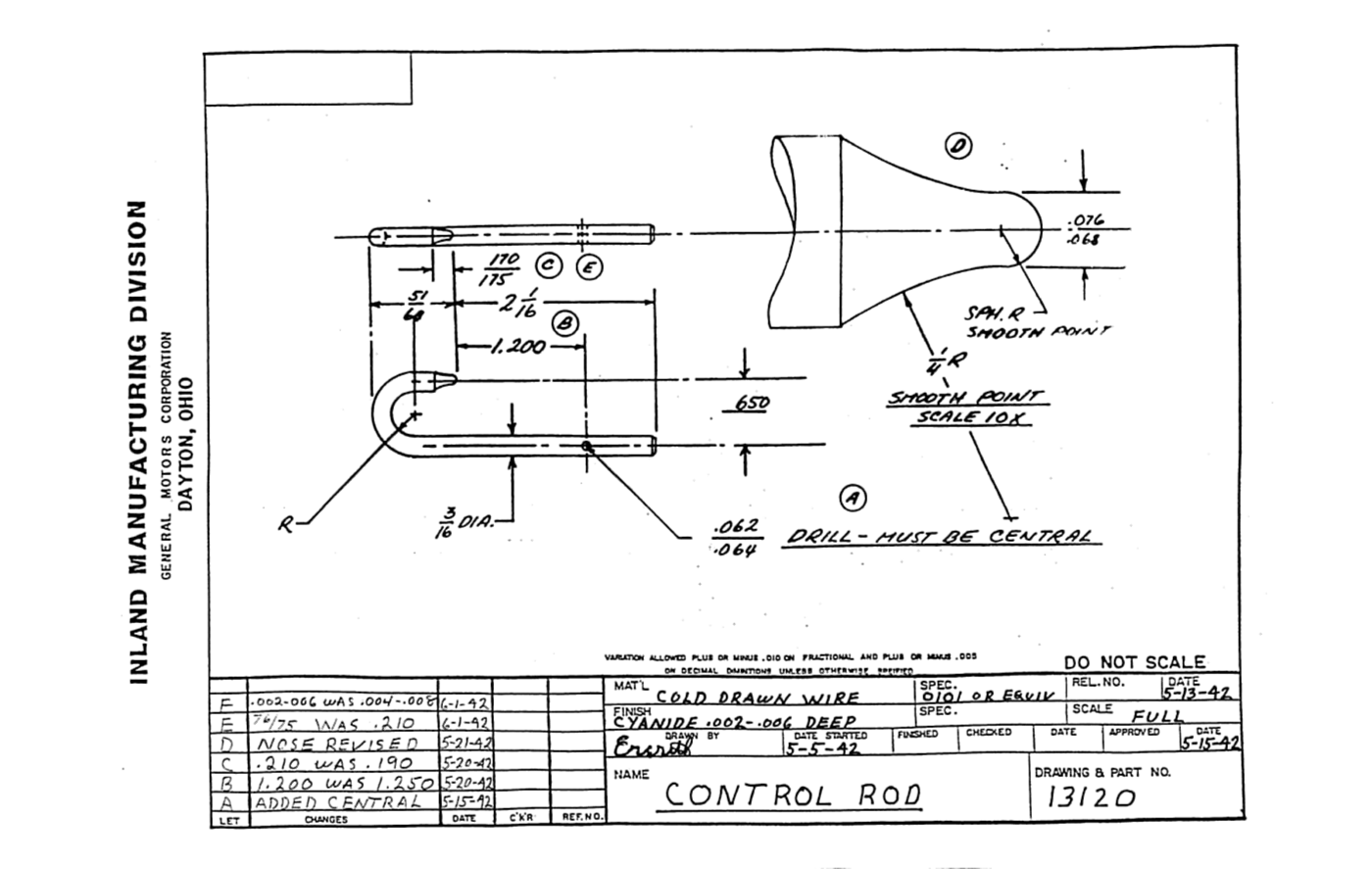
| Control Rod (firing pin) | 13120 | Cold-drawn wire, cyanide case-hardened .002–.006″ deep | 2-1/16″ to first step; .062–.064″ drilled hole, central |
| Control Rod Assembly | 13124 | Zinc die cast body + steel guide pin | guide pin 13124-1 is C.R.S., .125″ ±.002″ dia. |
| Snap Cover (mag/grip plate) | 13112 | C.R.S., half-hard 1010 | full-scale sheet-metal bend part |
| Shoulder Rivet / Rivet Yoke / Rivet Lock / Collar Pin | 13116 / 13117 / 13118 / 13123 | C.R.S. / steel wire (75,000 psi min tensile) | simple turned or wire-formed fasteners |
Three of these sheets deserve to be pulled and studied directly, because they are the parts a build lives or dies on:
- Tube, 13110 — the barrel. Note this is the smoothbore original geometry; a lab build substitutes a rifled blank (Volume 6) but the length, OD steps, and breech register transfer.
- Yoke Lever, 13114 — the four-radius cam that is the fire control. Machine this to the drawing.
- Control Rod, 13120 — the striker, with the central hole and case-hardening depth.
7.5 Translating 1942 Drawings Into CAD
A few practical notes for turning these sheets into modelable geometry:
- Read the title block and change tables. Each sheet carries its material spec (GM 1010, half-hard, case-hardening depths) and a revision history. The material and heat-treat callouts matter as much as the geometry for a firing build — capture them, then decide where to upgrade (Volume 6: 4140 over the original low-carbon C.R.S.).
- Translate the cover names as you go. Model the “tube” as a barrel, the “control rod” as a striker; keep a translation legend in your CAD project so the assembly reads correctly.
- Treat the smoothbore barrel as the one deliberate deviation. Everything else you copy faithfully; the bore you change to rifled, and the chamber you re-cut straight and correctly headspaced (Volume 6). Model the barrel with the real external steps and a rifled bore of the correct .45 caliber and 1:16″ twist.
- Rebuild tolerances for the joint that matters. The original’s loose tolerances are a stamping artifact (Volume 5). Model the breech joint to your tight headspace and heavier cross-section, not the drawing’s slop — the drawings give you shape and datum; you supply the modern fits at the breech.
- Use the display STLs only for gross shape. The Thingiverse/Cults3D/MakerWorld models (Volume 3) are useful to sanity-check overall proportions and the cam/striker envelope, but they are non-functional props with blocked chambers — every functional dimension comes from these drawings, never from a prop file.
With the drawings in CAD and the build paths from Volume 6 chosen, the last piece is sourcing and the buy-versus-build decision — Volume 8.
7.6 Bibliography
Footnotes
-
Google Patents inventor/assignee searches for George Hyde, Inland Manufacturing, and Guide Lamp Division (1942–45); no FP-45-specific patent found. https://patents.google.com/ ↩
-
George Hyde (gun designer). Wikipedia. https://en.wikipedia.org/wiki/George_Hyde_(gun_designer) — other patents (Model 35 / M3 lineage, rifle US 2,376,057), none covering the Liberator. ↩
-
Ralph Hagan, The Liberator Pistol: Development, Production, Distribution (1996), factory drawing scans. Survivor Library. https://www.survivorlibrary.com/library/liberator_pistol_blueprints.pdf — drawing numbers 13108–13133, cover-name cross-reference, per-part dimensions and specs (directly read, ~20 pages). ↩ ↩2
-
Mirrors of the same set (not independently verified page-by-page). Scribd. https://www.scribd.com/doc/82639402/Liberator-Pistol-Blueprints and https://www.scribd.com/document/47284314/Pistol-Liberator-Blueprints-1942 ↩
Comments (0)