FP-45 Liberator — Repros & DIY · Volume 5
Build Path A — The Original Method, and Why You Won't Use It
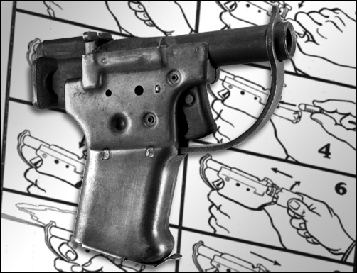
Before spending a volume on how to machine a Liberator, it is worth one volume on how it was actually made — both because the original method is a small marvel of wartime industrial design and because understanding it explains, precisely, why a builder with a mill will not replicate it. The FP-45 was engineered around a single overriding constraint: make a million of them, fast, cheap, with unskilled labor. Every design decision follows from that. At a quantity of one, every one of those decisions inverts. This volume documents the original progressive-stamping method, the die work behind it, and the clean logic of why it made sense at 1,000,000 units and none at all at 1 — which is the setup for the lab build in Volume 6.
5.1 The Original Production Facts
The wartime FP-45 was built from roughly 23 largely stamped and turned steel parts, assembled by riveting and spot-welding, produced by about 300 workers over roughly 11 weeks (June–August 1942) at General Motors’ Guide Lamp Division plant in Anderson, Indiana, at a unit cost of $2.10.1 Guide Lamp was a lamp and sheet-metal-stamping operation — that is the entire point. The Liberator was designed to be built by the same presses, tooling, and semi-skilled workforce that stamped car headlight housings, because that capacity existed, at scale, immediately, and needed no gunsmiths.
The design’s cover-name scheme underlines how far this was from conventional gunmaking: the engineering drawings called the barrel a “tube,” the trigger a “yoke,” the firing pin a “control rod,” the trigger guard a “spanner,” and the magazine door a “snap cover” (Volume 7), partly for secrecy and partly because the parts genuinely were generic stampings and turnings, not recognizable firearm components on a shop floor.
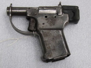
5.2 Progressive Stamping and Drawing
The core of the method is the progressive die: a multi-station stamping tool through which a strip of flat cold-rolled steel feeds, advancing one station per press stroke, with each station performing one operation — pierce, blank, form, draw, trim — so that a finished part (or most of one) drops out at the end of the strip. The receiver/cover shell, the grip halves, the trigger guard, and the snap cover were all formed this way from flat C.R.S. blanks, in stock gauges the factory drawings spec as thin as .025 to .125 inch for the grip, cover, and snap-cover parts (Volume 7).2
Two forming operations matter for understanding the shape:
- Blanking and piercing — punching the flat outline and holes of each part out of strip stock. Fast, repeatable, and exactly what a stamping plant already does all day.
- Drawing and bending — pulling and folding the flat blank into three-dimensional form: the U-shaped receiver cover, the rolled or folded grip walls, the formed trigger guard. On a progressive die this happens in stages across several stations so the metal is not overstressed in one pull.
The barrel (“tube,” drawing 13110) was a turned part — C.R.S., seamless, 4 inches long, with a stepped OD tapering from about 11/16 inch down to a small muzzle diameter — not a stamping, because a bore has to be drilled and reamed on a lathe or screw machine.2 Assembly then used spot-welding and riveting: the tube-and-strap assembly was arc-welded, grips were projection-welded to their rivet bosses, and the whole thing was pinned and riveted together. No fitting, no hand work, no headspace setting — the tolerances were loose by design (Volume 2’s .020-inch headspace slop is the direct result), because at $2.10 and ten rounds of intended life, precision was not the objective.
5.3 Why the Method Made Sense at 1,000,000
The economics are the design. A progressive die is enormously expensive to cut and prove — but once it exists, it stamps a part every press stroke, essentially for the cost of the strip stock and the electricity. Amortized across a million units, the die cost per part rounds to nothing, and the marginal labor is a semi-skilled worker feeding strip and tending a press. The result was a functioning pistol for the price of a couple of movie tickets, built in eleven weeks by people who had never made a gun. As a piece of wartime manufacturing engineering, it is genuinely elegant: the whole design is bent around the shape of the tooling and workforce that were available, not around what makes a good pistol.
5.4 Why It Makes None at 1
For a builder making one Liberator, every term in that equation flips:
- The tooling cost never amortizes. Cutting and proving a progressive die for a single pistol is absurd — thousands of dollars and weeks of die work to produce one part you could mill in an afternoon. There is no die shop in a home lab and no reason to build one.
- The design’s loose tolerances are a liability, not a feature. The original’s whole tolerance philosophy exists to make stamping cheap. A one-off builder wants the opposite — a tight, straight chamber and consistent headspace (Volume 6), because the original’s slop is precisely what fatigued the gun to failure at 27–35 rounds (Volume 2).
- The material is wrong for any real service life. The original’s low-carbon, largely un-heat-treated C.R.S. is a stamping-friendliness choice; it is also why the gun survived only tens of rounds. A builder can and should use better steel (Volume 6), which stamping’s constraints discouraged.
- The failure-prone joints are unnecessary. Spot-welds and rivets were the fast mass-assembly method. A one-off build can TIG-weld, braze, pin, or screw a stronger, more controllable joint (Volume 6) with no production-line to serve.
In short: the progressive-stamping method is the correct answer to “how do you make a million disposable pistols with a lamp factory,” and the wrong answer to every question a shop with a CNC mill actually faces. The one thing worth taking from the original method is the geometry, not the process. Every stamped part in the surviving factory drawings is dimensioned in a way that translates cleanly to two substitutions a lab can execute: solid-billet CNC machining, or laser-cut flat blanks bent on a press brake and welded — both covered in Volume 6. The drawings are a gift; the dies are a museum piece.
Volume 6 takes the geometry the original method produced and rebuilds it the way a modern shop should — for strength, tight headspace, and a real service life — starting from the two lab paths and the one non-negotiable safety fact about an unlocked .45 ACP breech.
5.5 Bibliography
Footnotes
-
FP-45 Liberator. Wikipedia. https://en.wikipedia.org/wiki/FP-45_Liberator — 23 parts, riveting/spot-welding, 300 workers, 11 weeks, $2.10, Guide Lamp Division. ↩
-
Ralph Hagan, The Liberator Pistol: Development, Production, Distribution — factory drawing scans. Survivor Library. https://www.survivorlibrary.com/library/liberator_pistol_blueprints.pdf — tube (13110) as a turned part, stock gauges .025–.125”, cover-name scheme. ↩ ↩2
Comments (0)