FP-45 Liberator — Repros & DIY · Volume 6
Build Path B — The Lab Build
This is the volume the whole series exists for. A well-equipped modern shop has what the original design never imagined — a CNC mill, a CNC router, 3D printers, a 100 W large-format laser, and a full gunsmithing bench — and the FP-45 is small enough to build well on that equipment in a way the wartime factory could not. The goal here is not to reproduce a $2.10 disposable pistol. It is to take the Liberator’s geometry (Volume 7) and rebuild it the way a modern shop should: rifled (so it is an ordinary Title I pistol, not an AOW — Volume 4), with a straight, correctly headspaced .45 ACP chamber, in steel worth the name, with a breech joint sized for real margin above the original’s demonstrated failure threshold. What follows is the machinist-level treatment: the two build paths, materials, wall thickness and breech strength, chamber and headspace, the striker and sear geometry, fixtures, finishing, failure modes, and proof-testing. It leans on the real factory dimensions in Volume 7 throughout.
6.1 Two Lab Paths to the Receiver
The Liberator’s “receiver” is really a sheet-metal shell — a cover slide and tube strap holding a barrel and a spring-driven striker. There are two sensible ways to make that in a modern shop, plus a hybrid worth naming.
Path B1 — CNC-milled from billet or plate. The most dimensionally controllable path and the recommended one. Start from 3/16 to 1/4 inch mild steel or 4140 plate and mill the cover-slide/tube-strap geometry as two or more solid pieces rather than folded sheet, then pin, screw, or weld them together. You trade period authenticity (the original was thin folded sheet) for a large strength margin, and in doing so you directly attack the original’s documented weak point — the thin stamped cover slide and tube strap that bowed at 27 rounds and became unsafe by 35 (Volume 2). Solid milled walls simply do not fatigue the way .025-inch folded sheet does.
Path B2 — laser-cut flat blanks + press-brake forming. Closest in spirit to the original stamping process, and a good fit for the 100 W laser. The Hagan drawings spec the grip, cover, and snap-cover stock as thin as .025 to .125 inch (Volume 7), and a 100 W CO₂ laser cuts thin mild steel — roughly up to ~3 mm (.12 inch) — cleanly, losing speed and edge quality fast beyond that. That envelope lines up almost exactly with the original’s sheet gauges. Cut the flat blanks on the laser, form them on the press brake, then TIG-weld or braze the seams in place of the original’s spot-welds and rivets — a stronger, more controllable joint for a one-off than trying to replicate factory projection welding. This path reproduces the authentic thin-shell architecture; if you take it, you must respect the breech-strength discussion below, because you are back near the original’s material limits at the one joint that matters.
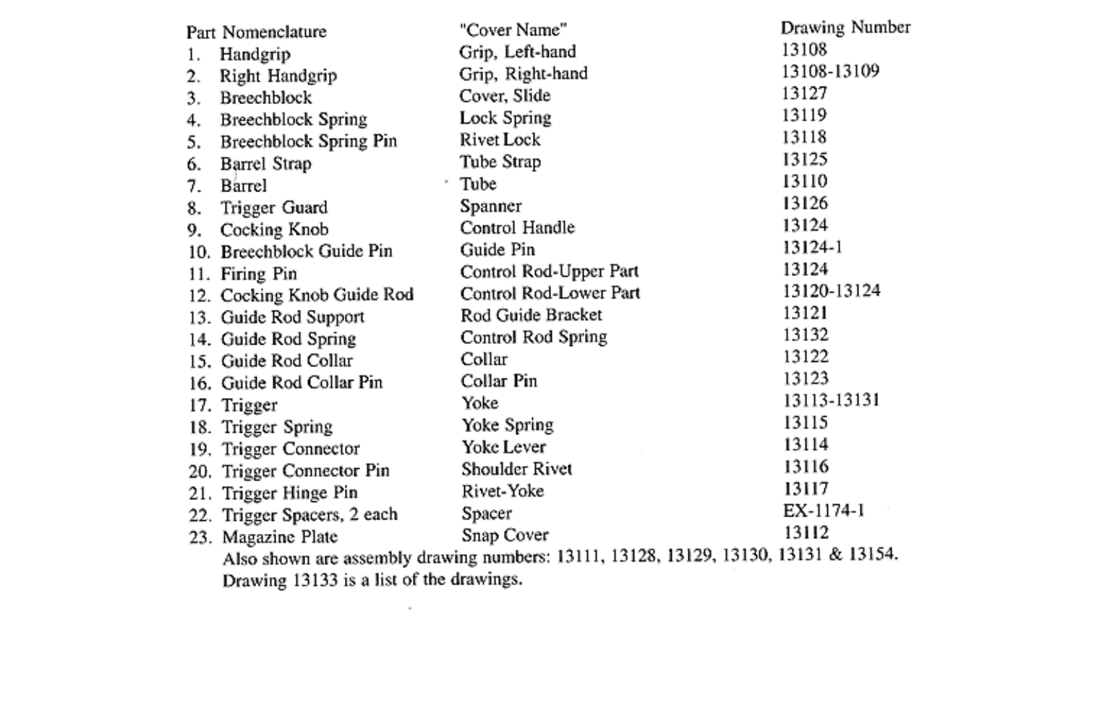
Path B3 — tube-based receiver/breech (hybrid). Start the receiver/breech from seamless DOM or C.R.S. tube stock matching the Hagan “Tube” drawing (13110) directly. This is the most natural fit if the barrel itself is being turned from bar stock on the lathe, because barrel and receiver-tube can share lathe setup and datum. A tube breech is inherently stronger in hoop than a folded strap and is a clean way to get margin without full billet machining.
The recommendation for real service life is B1 (milled) for the breech-critical parts and the laser (B2) for the flat, non-load cosmetic parts — cover panels, grip skins, snap cover, trigger guard. Use each tool where it is strong.
6.2 Materials, Wall Thickness, and Breech Strength
The original’s low-carbon, largely un-heat-treated C.R.S. is the reason it survived only tens of rounds — it is a spec to understand, not to imitate. Three material tiers, in ascending order of service life:
- Original spec — low-carbon C.R.S., no heat treat. Historically accurate, mechanically poor. Reference only.
- Vintage Ordnance’s minimum bar — 1050 medium-carbon cold-rolled steel for barrel, tube strap, and cover slide, with tightened chamber tolerances (Volume 2). A reasonable floor for a firing build.
- Recommended — 4140 chromoly, properly heat-treated (quench and temper the cover slide, tube strap, and barrel in particular). This is well within normal gunsmithing practice and gives the fatigue-critical joint real margin.
Now the number that governs the whole design. .45 ACP SAAMI maximum average pressure is 21,000 psi (23,000 psi for +P).1 The research states this as the SAAMI figure directly; treat it as the design pressure with normal confidence. What makes 21,000 psi consequential on a Liberator is the architecture: the breech is not locked. There is no rotating bolt, no locking lug, no tilting barrel. The chamber pressure at the instant of firing is contained purely by the tensile and shear strength of the cover-slide/tube-strap joint and its fasteners holding the breech end closed against the barrel. The original’s failure mode — cover slide and tube strap bowing after 27 rounds — is a direct demonstration of how thin that margin is even at standard SAAMI pressure. It is not a wartime-defect artifact; it is the fundamental unlocked-breech architecture reaching its limit. Vintage Ordnance’s reproduction pushes the failure point out with thicker, better steel — it does not change the architecture.
The design consequence: treat the breech joint (the barrel-strap / tube-to-cover-slide interface) as the single most safety-critical dimension in the whole gun. Size the wall thickness and strap cross-section for real margin above the original’s demonstrated failure threshold — this is exactly where Path B1’s solid milled walls or Path B3’s tube hoop earn their keep over Path B2’s folded sheet. Do not copy the original’s cross-sections; copy its geometry and scale up the material at the breech.
6.3 Chamber and Headspace on Rimless .45 ACP
The original’s chamber was conical, not straight, with headspace as loose as .020 inch of free play between cover slide and barrel breech — and that pairing is the named root cause of the 27-to-35-round failure (Volume 2). A lab build fixes both.
Cut a correct, standard, straight .45 ACP finish-reamed chamber to SAAMI tolerances, not the original’s crude taper-reamed approximation. The critical detail for a builder: .45 ACP is a rimless straight-wall case that headspaces on the case mouth, not on a rim and not on a belt. That means the chamber must be reamed to a precise depth so the case mouth stops on the chamber-mouth step, and the breech face must be positioned so a chambered round is held with minimal, consistent free play — the opposite of the original’s .020-inch slop. Use a standard .45 ACP finish reamer, set depth against a case-mouth gauge (or a properly gauged dummy/GO reference), and confirm headspace with the appropriate method for a case-mouth-headspacing pistol cartridge. Tight, consistent headspace is not a refinement here; it is a primary reason the original fatigued and a primary defense against battering the breech face on this build.
6.4 Barrel: Buy a Rifled Blank
The barrel decision is settled by two facts at once, and they point the same way: buy an off-the-shelf rifled .45-caliber barrel blank.
- Legally, the rifled bore is what makes this an ordinary pistol rather than an AOW (Volume 4). The rifling must be real lands and grooves — the standard .45 ACP twist is typically 1:16 inch — not a cosmetic groove. A purchased rifled blank guarantees genuine rifling.
- Practically, rifling a barrel is its own substantial project. Cutting or button-rifling a bore in-house needs a rifling head or broach and is a discipline unto itself; the Hackaday builder hand-cut rifling with a shop-built hacksaw-blade broach, slowly, by hand, as a demonstration that it can be done — not as an efficient path.2 For a Liberator build, the barrel is not where you want to spend the effort; buy the blank rifled and spend your machining time on the breech and chamber.
UNVERIFIED: no specific barrel-blank vendor was confirmed in research — do not order against an invented vendor name. Go-to barrel suppliers may already be established from other builds in this hub; cross-check the hub’s shared notes and the AK barrel-build work referenced there before establishing a new supplier. Volume 8 covers sourcing generically. The in-house rifling option (b) exists only if the shop has or improvises a rifling head, and even then the bought blank is the sane default.
6.5 Striker, Sear Geometry, and Springs
The Liberator’s fire control is refreshingly simple, and the factory drawings give it exactly (Volume 7). Three things a builder should internalize:
- The “sear” is a flat cam, not a hooked sear. The Yoke Lever (drawing 13114) is a cam whose profile is built from four blended radii — approximately .032R / .075R / .150R / .125R — and that cam profile is the sear geometry. It is a flat cam follower releasing the striker, not a conventional engagement hook. Cut the cam profile to the drawing; that is the whole trigger mechanism.
- The striker is a spring-driven pin. The “Control Rod” (drawing 13120) is the firing pin — cold-drawn wire, cyanide case-hardened .002–.006 inch deep in the original, about 2-1/16 inch to the first step, with a central .062–.064 inch hole. It rides in a zinc-cast collar assembly (13124). A builder can reproduce it in a suitable steel and case-harden or nitride the tip; keep the striker-hole central so ignition is consistent.
- Springs are music wire, stress-relieved. The Yoke Spring (13115) is music wire, ~3/4 inch arm, ~20° working range, ~2.5 lb max load, and — per the drawing — must not take permanent set. The Lock Spring (13119) is 6-coil, left-hand-wound music wire over a 3/16 inch rod. These are standard small-spring practice, easily reproduced or upgraded: substituting a slightly heavier music-wire gauge gives more reliable ignition without deviating from the original geometry. Reproduce the geometry; feel free to firm up the spring rates for reliable primer strikes.
6.6 Fixtures and Workholding
The parts are small, which makes workholding the quiet difficulty. A few notes for the shop:
- Barrel/breech concentricity is the whole ballgame. If you take the tube path (B3), do the bore, chamber, and breech register in as few setups as possible — ideally chuck the barrel blank and ream the chamber and cut the breech register on one lathe setup so they share a datum.
- The cover slide and tube strap want a fixture that holds the breech-face position relative to the barrel breech at the designed (tight) headspace during weld/braze or pinning, because that relationship is the safety-critical dimension. Make or print a setting fixture that positions the parts at final headspace before you fix the joint.
- Small flat parts (grips, snap cover, trigger guard, cam) are laser-cut jobs; hold the milled cam blank in a vise with a machinable soft jaw or a printed fixture to cut the four-radius profile accurately.
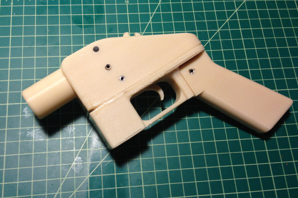
- Prototype in printed plastic first. Print the whole assembly (the Thingiverse/CAD geometry from Volume 3 as shape reference) to check fit and the cam/striker interaction before committing steel. Printed prototypes are for fit only — never a firing part (Volume 4’s UFA note).
6.7 Failure Modes and Proof-Testing
Be candid: this is an unlocked-breech .45 at 21,000 psi, and the honest failure modes are known from the original’s own history. Plan for:
- Stretched or loosened strap rivets/fasteners, progressively opening headspace shot to shot.
- Cover-slide and tube-strap bowing — the original’s 27-round mode. Solid milled or tube-hoop breech construction is the defense.
- Progressively increasing headspace with each shot as the breech batters — mitigated by starting tight and using heat-treated 4140.
- At the extreme, case-head separation or blowback past a battered breech face — the reason proof-testing is non-negotiable.
Proof-test remotely. Fire the first rounds — a proof load, then initial standard rounds — with the pistol fixed in a rest and fired by lanyard or remote actuation from behind cover, never hand-held, until you have confirmed the breech joint holds and headspace stays consistent. Inspect the breech joint, strap, and headspace between strings. Understand from the outset that even a good build is a low-round-count firearm by architecture — the original was “made to fire ten rounds” (Volume 2), and while better steel and tight headspace push that out meaningfully, this is a study/novelty firing piece, not a range gun you feed hundreds of rounds. Build it to be safe for its intended handful of rounds, verify that remotely, and treat every increase in headspace or any bowing as a stop-and-inspect signal.
Volume 7 is the drawing set that makes all of this dimensioned rather than guessed; Volume 8 is sourcing and the buy-versus-build math.
6.8 Bibliography
Footnotes
-
.45 ACP. Wikipedia. https://en.wikipedia.org/wiki/.45_ACP — SAAMI maximum average pressure 21,000 psi (23,000 psi +P), 1:16” typical twist. ↩
-
Building a Sheet Metal Pistol. Hackaday, 2016. https://hackaday.com/2016/02/17/building-a-sheet-metal-pistol/ — in-house hand-cut rifling with a hacksaw-blade broach. ↩
Comments (0)