Positional and Inertial Aiming · Volume 6
An IMU for This Gun — What It Adds, Which Part, and What It Costs on the Pico
Nobody has shipped a light gun with a gyroscope in it. What one could add to the OpenFIRE gun with the PAJ7025R3 camera — bridging lost markers, telling off-screen from lost, gesture reloads, seeing the recoil kick — ranked by value; four candidate parts compared, with why and why not; where it fits on a Pico with no free pins; a firmware sketch; and the bench tests that decide it
6.1 Prior Art: None Found
No light gun, commercial or open-source, was found that uses an inertial sensor for aiming. The OpenFIRE firmware has none: a code search of TeamOpenFIRE/OpenFIRE-Firmware on 2026-10-19 found no occurrence of “gyro” or “accelerometer”, and the hits for “IMU” were substrings of other words; the counter-search for “tilt” found only the square and diamond layout code, which recovers the camera’s roll from the markers. Web searches for gyroscope or IMU light-gun builds found gyro gamepads, head trackers and motion controllers, and no light gun. The nearest products are the hybrids of Volume 4 — the Wii Remote with MotionPlus and the PlayStation Move — neither of which was a dedicated light gun.
So everything below is a proposal for this project’s firmware fork (Our Firmware), not a description of anyone’s working gun. Nothing has been bought or built.
6.2 What an IMU Could Add, Ranked
1. Telling “off the screen” from “lost”. OpenFIRE decides the gun is off-screen when its computed position is pinned at the edge of its range (Open-Source Firmware, Volume 2), and that needs the camera to still see the emitters while the gun points past the edge. IR Point Tracking, Volume 4 works out how much further back the player must stand for that, and leaves open what the firmware does when the points are lost entirely. A gyroscope answers it: if the camera’s last fixes were moving toward the left edge and the gyroscope says the gun kept turning left, the gun is off the screen to the left — report off-screen, and the off-screen trigger pull becomes a reload in the games that expect one. If the gyroscope says the gun barely moved, the markers were blocked (a hand, a second player) — hold the last position. This is the most useful thing an IMU can do here, and it needs only a few degrees of accuracy.
2. Bridging short gaps. When the markers drop for a fraction of a second while the gun is still on the screen, the gyroscope carries the aim from the last fix with an error of a few pixels for its bias and scale (Volume 4, §4.5). The camera keeps the bias learned while it can see. OpenFIRE’s own fourth-point reconstruction (IR Point Tracking, Volume 3) covers one missing point; the gyroscope covers zero visible points. Neither sees the player stepping sideways, so the bridge must stay short and blend back.
3. Gesture reloads and controls. Gravity tells the gun when it is pointed at the floor or the ceiling, and the accelerometer sees a sharp shake or a flick. A “point down to reload” gesture works with the camera blind and with no button; a flick can stand in for a pump on a gun that has none. These are cheap and unambiguous.
4. Seeing the recoil. The firmware knows when it fires the solenoid; an accelerometer tells it what the gun did. Two uses follow. Gating: during the kick the accelerometer is not measuring gravity and the camera’s image smears as the gun jerks, so the fusion should stop learning bias and gravity for the pulse (Volume 4, §4.2). Compensation: the camera sees the gun jump on every shot and the cursor jumps with it; holding the reported aim at its pre-shot value until the IMU says the gun has settled — rather than for a fixed time — keeps the cursor still through the kick. Whether the jump is large enough to matter is a bench question (§6.8); it depends on the solenoid (Solenoid Recoil) and the gun’s mass.
5. Roll when the markers are gone. The camera measures roll from four markers; the accelerometer measures it from gravity whenever the gun is still enough. It matters only inside a bridged gap, where the gyroscope’s two rates have to be rotated by the roll to mean left and up on the screen (Volume 4, §4.8).
What an IMU will not do is replace the camera, improve the aim while the markers are in view, or see the player move sideways (Volume 1, §1.5).
6.3 The Candidate Parts
Table 1 — 6.3 The Candidate Parts
| Part | Gyro offset tempco | I²C | FIFO | Bench breakout, price (2026-10-19) | Notes |
|---|---|---|---|---|---|
| TDK ICM-42688-P | ±0.005 °/s/°C | to 1 MHz; SPI to 24 MHz | 2 kB | LogicalEdges breakout, Tindie, US$88.00, “Only 5 left”;1 bare part LCSC C1850418, US$21.00 each for one2 | Lowest tempco and noise of the three; no common cheap breakout |
| ST LSM6DSOX | ±0.010 °/s/°C | 400 kHz (Fm+ characterised) | 9 kB | Adafruit 4438, US$11.95, in stock3 | Finite-state machines and machine-learning core for on-chip gestures; STEMMA QT |
| Bosch BMI270 | ±0.015 °/s/K | to 1 MHz | 2 kB | SparkFun SEN-22397, US$18.50, in stock4 | 8 kB configuration blob at every power-up; wearable features unused |
| CEVA BNO085 | (fusion part) | I²C, SPI, UART-RVC | — | Adafruit 4754, US$29.50, in stock5 | On-chip fusion; yaw from a magnetometer or drifting; see Volume 4, §4.7 |
All gyroscope figures are from the datasheets in Volume 3, typical values. The LCSC price for the bare ICM-42688-P is recorded as read; it is high for a consumer IMU and should be rechecked before ordering for a carrier build.
6.4 Why This, and Why Not the Others
Criteria, in order: (1) the gyroscope’s offset tempco, because the gun warms and that is what sets the bridged error (Volume 3, §3.5); (2) works on the shared 400 kHz peripheral bus (§6.5) and can buffer through an OLED frame; (3) easy to try on the bench now; (4) no start-up baggage; (5) price.
Proposed: a two-step pick.
- Bench trial: Adafruit LSM6DSOX (4438). US$11.95, in stock, STEMMA QT so it plugs into the Pico’s peripheral bus with a cable, a 9 kB FIFO that rides through an OLED frame with room to spare, and on-chip gesture state machines for job 3. Its tempco is twice the ICM-42688-P’s, which is exactly what the bench test in §6.8 measures: if the LSM6DSOX bridges well enough in the warm gun, the question is closed cheaply.
- Carrier part: TDK ICM-42688-P, if the bench shows the tempco matters. It has the lowest offset tempco (a third of the BMI270’s), the lowest noise, a 2 kB FIFO, and a small LGA footprint for the four-layer carrier (Reference Electronics, Volume 8). Its price should be checked across distributors before committing.
Why not the others:
- BMI270 — the highest tempco of the three, and the 8 kB configuration file that must be written at every power-up (184 ms at 400 kHz) to unlock features a gun does not use. Nothing in it is better for this job than the other two.
- BNO085 — its fusion is the wrong fusion: the gun’s only yaw reference is its own camera, so the correction has to run on the RP2040 anyway, and the on-chip magnetometer is ruled out beside a solenoid (Volume 3, §3.8). It costs two to three times as much.
- Older parts (the MPU-6050 class) common in hobby gyro builds were not compared: three current parts with complete datasheets cover the choice.
6.5 Where It Fits on the Pico
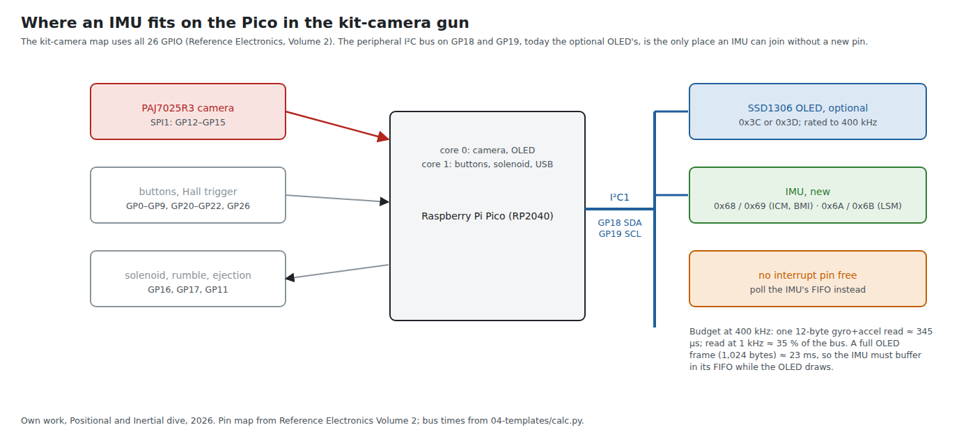
Reference Electronics, Volume 2 sets the constraint: with the kit camera on SPI1 the Pico carries “26 functions on 26 GPIO, with nothing spare”. Two consequences follow.
The IMU goes on the peripheral I²C bus. I2C1 on GP18 and GP19 carries the optional SSD1306 OLED at 0x3C or 0x3D (Open-Source Firmware, Volume 5); the IMU candidates answer at 0x68/0x69 (ICM, BMI) or 0x6A/0x6B (LSM), so there is no clash. The SSD1306’s own datasheet gives an I²C clock cycle time of at least 2.5 µs,6 so a bus shared with it runs at 400 kHz whatever the IMU could do.
There is no pin for the IMU’s interrupt. The firmware polls instead, which the FIFO makes cheap: read whatever has accumulated, once per camera frame or once per millisecond on the other core.
The bus budget at 400 kHz (from the dive’s calculation script):
Table 2 — The bus budget at 400 kHz (from the dive's calculation script)
| Traffic | Bus time | Share of the bus |
|---|---|---|
| One gyro + accel read, 12 bytes | about 345 µs | — |
| …at 209 reads a second (once per camera frame) | about 7 % | |
| …at 1,000 a second | about 35 % | |
| A full 128 × 64 OLED frame, 1,024 bytes | about 23 ms | blocks the bus |
The OLED is the problem, not the IMU. OpenFIRE draws the OLED on core 0 between camera reads, with blocking I²C (Open-Source Firmware, Volume 2). A 23 ms frame at a 1 kHz output rate leaves 23 samples, about 300 bytes, waiting in the IMU’s FIFO — inside the 2 kB of the ICM-42688-P and well inside the LSM6DSOX’s 9 kB. So the right design is to read the FIFO in bursts at the camera tick, never single samples, and to let the FIFO absorb the OLED. Without an OLED (it is optional) the bus is the IMU’s alone, and an ICM-42688-P could run it at 1 MHz.
The stopgap gun is easier. With the Wii-class camera on I2C0 and stock firmware, GP15 is the one spare pin (Reference Electronics, Volume 2), which can carry the IMU’s interrupt.
Not on SPI. Sharing the camera’s SPI1 would need a chip-select pin that does not exist. On an ESP32-S3 (route 2 for the kit camera, decision P-RE18), the pin count is not a constraint.
6.6 Placement in the Gun
- Square to the camera. The firmware works in the camera’s axes (Volume 4, §4.8); mounting the IMU with its axes parallel to the camera’s removes a rotation from the code and from the calibration. On the carrier board, which also carries the camera connector, that is a layout decision for the Altium capture.
- Away from the heat. The DRV8251A recoil stage dissipates in pulses (Reference Electronics, Volume 5). Every degree it puts into the IMU is 0.005 to 0.015 °/s of fresh bias (Volume 3). Distance, a ground-plane thermal break and the IMU’s own temperature sensor feeding a correction table are the three defences.
- Rigid to the receiver. The IMU has to move with the gun, not with a board flexing on standoffs. A flexing board turns the solenoid’s kick into a ringing the gyroscope reads as rotation.
- Not beside the solenoid’s steel. Irrelevant to the gyroscope and accelerometer, which are not magnetic sensors — the reason a magnetometer is not on the list (Volume 3, §3.8).
6.7 A Firmware Sketch
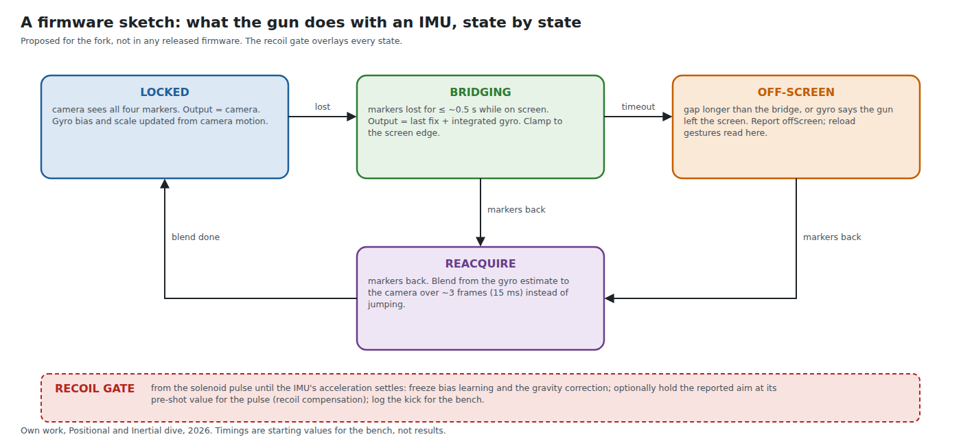
In outline, for the fork:
- Start-up. Configure the IMU (±2000 °/s, ±16 g, output rate 1 kHz, FIFO on), then a still-calibration of the gyroscope bias, triggered by stillness rather than a fixed delay.
- LOCKED. At each camera frame, drain the FIFO; integrate the gyroscope’s two screen-axis rates over the frame; compare with the camera’s change in aim (in degrees, from its pixels-per-degree); update a per-axis bias with a slow integral term (Mahony’s idea, Volume 4, §4.3). Log the IMU’s die temperature with it.
- BRIDGING. On losing the markers while the last fixes were inside the screen, output last fix plus integrated rate, rotated by the last known roll. Start with a 0.5 s limit.
- OFF-SCREEN. On timeout, or when the integrated motion carries the aim past an edge, set
offScreen. Read the gravity vector for a point-down reload. - REACQUIRE. When the markers return, blend from the bridged estimate to the camera over about three frames (15 ms at 209 Hz) rather than jumping.
- Recoil gate. From the solenoid pulse until the accelerometer’s magnitude is back within a band around 1 g: freeze bias learning and any gravity correction; optionally hold the reported aim (compensation, §6.2).
The fork’s structure, upstream tracking and licence obligations are Our Firmware’s; this is only the sensing logic it would carry.
6.8 Bench Tests
Each test uses the lab’s instruments (the Analog Discovery Pro ADP3450 and Analog Discovery 2, the programmable supplies) and decides one thing.
- Bus timing. ADP3450 logic analyser on GP18/GP19 with the OLED and the IMU both active: confirm the read time and that FIFO bursts survive an OLED frame without overflow.
- Drift at rest. An hour of gyroscope data at 1 kHz on the bench, Allan deviation computed on the PC: the bias instability none of the datasheets give.
- Drift in the warm gun. The IMU on the carrier beside the recoil stage, the solenoid firing at a game’s rate for ten minutes, logging bias and die temperature: the correction table of Volume 3, §3.6, and the answer to “is the LSM6DSOX enough?”
- Bridging. Pan across the screen and cover the camera for 0.25, 0.5, 1 and 2 s; compare the bridged aim with the camera’s first fix after uncovering. Repeat with a sideways step during the cover to see the translation error.
- Recoil. The IMU’s accelerometer logged through a shot alongside the ADXL1002 rig of Solenoid Recoil, Volume 6, and the camera’s aim logged through the same shot: how far the cursor jumps, for how long, and whether holding it helps.
6.9 Proposed Decision-Log Rows
Decided on 19 October 2026: an IMU goes on the first carrier (D36); the OLED stays, to show the ammo count later (D37), so the IMU shares its bus as PI-2 describes; the Adafruit LSM6DSOX breakout is bought for the bench trial (D38); a mounted gun is not planned (D39), so PI-4 is shelved. The rows as proposed:
Table 3 — Decided on 19 October 2026: an IMU goes on the first carrier (D36); the OLED stays, to show the ammo count later (D37), so the IMU shares its bus as PI-2 describes; the Adafruit LSM6DSOX breakout is bought for the bench trial (D38); a mounted gun is not planned (D39), so PI-4 is shelved. The rows as proposed
| # | Area | Candidates | Pick | Status | Reason |
|---|---|---|---|---|---|
| PI-1 | IMU in the gun | none; LSM6DSOX; ICM-42688-P; BMI270; BNO085 | Bench-trial Adafruit LSM6DSOX (4438); ICM-42688-P on the carrier if warm-gun drift demands it | Proposed | Lowest tempco wins the carrier; cheapest in-stock board answers the question first; BMI270 highest tempco plus 8 kB blob; BNO085 wrong fusion and a magnetometer beside a solenoid |
| PI-2 | IMU connection (kit-camera Pico) | I2C1 shared with OLED; SPI1 shared with camera; drop OLED | I2C1 (GP18/GP19) at 400 kHz, FIFO polled, no interrupt | Proposed | No free GPIO (26/26); SPI needs a CS pin; SSD1306 limits the bus to 400 kHz; FIFO absorbs a 23 ms OLED frame |
| PI-3 | Magnetometer | include; exclude | Exclude | Proposed | Pulsed solenoid and steel plunger beside it; degrees of heading error per µT indoors |
| PI-4 | Mounted-gun angle sensor (future cabinet build) | AS5600L; AS5600; geared pot; encoder | AS5600L direct on each pivot | Proposed | No wear, absolute, two axes on one bus; see Volume 2, §2.9 |
6.10 What Could Not Be Verified
- That no light gun anywhere uses an IMU: only what was searchable on 2026-10-19 was searched.
- The size of the cursor jump during a recoil kick: no measurement exists for this gun.
- The ICM-42688-P’s distributor prices beyond the one LCSC listing read, and any cheaper stocked breakout.
- Whether the arduino-pico core’s I²C driver in the fork’s build reads a FIFO burst efficiently enough; to be confirmed on the bench (test 1).
Sources
Footnotes
-
LogicalEdges, “ICM-42688-P Ultra-Low Power IMU Breakout”, Tindie, https://www.tindie.com/products/led/icm-42688-p-ultra-low-power-imu-breakout, read 2026-10-19. ↩
-
LCSC, product C1850418, TDK InvenSense ICM-42688-P, https://www.lcsc.com/product-detail/C1850418.html, read 2026-10-19 (US$21.0006 at 1, US$18.7422 at 10, US$16.2961 at 100; 1,908 in stock). ↩
-
Adafruit, “Adafruit LSM6DSOX 6 DoF Accelerometer and Gyroscope - STEMMA QT / Qwiic”, product 4438, https://www.adafruit.com/product/4438, read 2026-10-19. ↩
-
SparkFun, “SparkFun 6DoF IMU Breakout - BMI270 (Qwiic)”, SEN-22397, https://www.sparkfun.com/sparkfun-6dof-imu-breakout-bmi270-qwiic.html, read 2026-10-19. ↩
-
Adafruit, “Adafruit 9-DOF Orientation IMU Fusion Breakout - BNO085 (BNO080)”, product 4754, https://www.adafruit.com/product/4754, read 2026-10-19. ↩
-
Solomon Systech, SSD1306 data sheet, revision 1.1, April 2008, Table 13-6 (I²C interface timing), as hosted by Adafruit, https://cdn-shop.adafruit.com/datasheets/SSD1306.pdf, read 2026-10-19. ↩
Comments (0)