Positional and Inertial Aiming · Volume 2
Angle Sensors on a Mount — Potentiometers, Gears, Magnets and Encoders
The engineering under the arcade's fixed guns: how many distinct readings each sensor gives across a screen, why the arcade geared its pots, what a 12-bit magnetic angle sensor really resolves when its range is narrowed, why the angle-to-screen map is a tangent, and which sensor a mounted gun built today should use
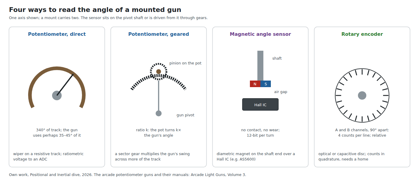
2.1 A Gun That Cannot Translate
A gun on a two-axis mount is the one aiming problem in this dive that is genuinely easy. The pivot is fixed to the cabinet, so the gun cannot step sideways; the only things that change are yaw and pitch, and each is the angle of a shaft. Measure the two shafts and the aim is known, absolutely, with an error that does not grow. Nothing about the display matters, which is why makers used it for projection cabinets from 1988 and still sell it on flat-panel cabinets today. The cabinets, their part numbers and their calibration screens are in Arcade Light Guns, Volume 3; this volume is the engineering behind them, and what a mount built now would use.
The useful way to compare the four is to count distinct readings across the screen. In the reference room of Volume 1 — a 55-inch screen at 2 m — the picture spans 33.9° of yaw and 1920 pixels. A sensor that delivers fewer distinct readings than that over 33.9° makes the cursor step; one that delivers many more lets the firmware filter without losing detail.
2.2 Potentiometers
A potentiometer used as an angle sensor is a voltage divider: excitation across the track, the wiper’s voltage to an ADC. Read against the same reference that excites it, the reading is ratiometric — a fraction of the track — so supply drift and the track’s resistance tolerance and temperature coefficient cancel. What is left is the track’s linearity, its noise, and its wear.
Electrical travel. Single-turn panel pots have an electrical rotation a little under a full turn; Bourns’ 6639 conductive-plastic series, for example, is listed at 340° (distributor listing; the Bourns data sheet could not be downloaded on the day).1 A gun that swings ±17° to cover the reference screen uses only a tenth of that.
Track material. Carbon composition is cheap and wears; conductive plastic is the material for a pot that is turned continuously, with a smooth output and long life; wirewound tracks resolve in discrete steps, one per turn of wire, and are a poor fit for a fine angle. TT Electronics’ BI 6173 conductive-plastic single-turn series is a representative current part: linearity 0.5 %, minimum cycle life 5,000,000, 1 kΩ to 100 kΩ, 10 % resistance tolerance (maker’s product page, read 2026-10-19).2 The arcade manuals call for “Potentiometer, 5K, Long Life” (Midway, Terminator 2) and “Long life pot” (Raw Thrills, Aliens Armageddon) — conductive-plastic language — and Midway’s manual warns the operator not to calibrate by turning the pots, because calibration is software (both quoted in Arcade Light Guns, Volume 3).
What 0.5 % linearity means at the gun. 0.5 % of a 340° track is 1.7°: 93 pixels at 2 m if the pot sits directly on the pivot and is not calibrated beyond its end points. A multi-point calibration takes out the smooth part of that error; the rest is the reason arcade guns are calibrated at three points rather than two.
Wear and noise. A pot that wears develops a worn band where the gun spends most of its time — the middle of the screen — and the wiper’s contact becomes intermittent there. The symptom is a cursor that jumps near the centre. It is the most common failure of a positional gun, and the reason the manuals list the pots as service parts.
2.3 Reading a Pot on the RP2040
The RP2040’s ADC is 12-bit with an effective resolution the datasheet gives as 8.7 ENOB, and an erratum (RP2040-E11) adds differential non-linearity spikes at four codes; Reference Electronics, Volume 2 covers both, and why they do not matter for a Hall trigger read as a threshold. They matter for a pot read as a position.
At 8.7 effective bits, 2^8.7 ≈ 416 distinguishable levels span the whole 340° track: 1.22 per degree. Across the 33.9° screen that is 41 readings — one per 47 pixels. A direct-coupled pot on a Pico’s ADC cannot aim a gun at 1080p without averaging.
Oversampling helps, within limits. The RP2040’s ADC converts at 500 ksps, so averaging 64 samples per axis per millisecond is free; if the noise is white and wide enough to dither the converter, averaging N samples adds about log₂(√N) bits, three bits for 64 samples. It does not fix DNL, and E11’s code spikes do not average away. Two cheaper fixes exist and the arcade used both: gear the pot so the gun’s swing covers more of the track (§2.4), and use a better converter — the Taito boards read their pots through an ADC0808 (MAME’s notes, quoted in Arcade Light Guns, Volume 3).
2.4 Gearing, and What It Costs
A sector gear on the gun’s pivot driving a small pinion on the pot multiplies the angle by the gear ratio k. With k = 6, the gun’s 34° becomes 204° of track and the RP2040’s ADC gives 248 readings across the screen instead of 41. Space Gun’s gun base, drawn in the Electrocoin manual reproduced in Arcade Light Guns, Volume 3, is exactly this: a sector gear (gear A) driving gear B on each axis, with a tension spring in the bracket.
Gearing has two costs.
- Backlash. Free play between the teeth appears as a dead band each time the gun reverses: the gun turns, the pot does not. At a 6:1 ratio a backlash of 0.5° measured at the pot is 0.08° at the gun, about 5 pixels, but backlash in the sector gear’s own bearing appears at the gun undivided. A spring that loads the pinion against one flank of the sector removes it, which is the likely purpose of the spring in Space Gun’s bracket (the manual draws it; it does not say why).
- The pot now turns further. At k = 6 every swing of the gun turns the pot six times as far, so its life in gun swings falls by six. Against a 5-million-cycle conductive-plastic part this is still a long life, but it is no longer one to ignore on a cabinet in daily use.
2.5 Magnetic Angle Sensors
A magnetic angle sensor puts a diametrically magnetised disc magnet on the end of the shaft and a Hall-effect IC under it, across a small air gap. The IC measures the direction of the field in its plane and reports the angle. There is no contact, so nothing wears, and the sensor does not care about dust.
The AS5600 (ams OSRAM, now Infineon’s after the acquisition that closed on 1 July 2026, per the notice on the hosted datasheet) is the common part:3
Table 1 — 2.5 Magnetic Angle Sensors
| Parameter | AS5600 datasheet value |
|---|---|
| Resolution | 12 bits per turn (4096; 0.088°) |
| System INL | ±1° (360°, no magnet displacement, no zero programming) |
| RMS output noise, 1σ | 0.015° with the slow filter (2.2 ms); 0.043° with the fast filter (286 µs) |
| Magnetic field | 30 to 90 mT orthogonal component |
| Interface | I²C at up to 1 MHz, fixed address 0x36; also a ratiometric analogue or PWM output |
| Programmable range | 18° to 360° (ZPOS / MPOS / MANG); the permanent burn can be done up to 3 times |
Two points in the datasheet are easy to miss and both change the design.
Narrowing the range does not add resolution. It is natural to assume that programming the output for an 18° to 40° window spreads 4096 codes over the window. The datasheet says otherwise: “In case of narrowed angular range, the resolution is not scaled to narrowed range (e.g. 0° to 360°(full-turn) → 4096dec; 0° to 180° → 2048dec).” The angle measurement is 12 bits per turn whatever the output window; narrowing the window only rescales the output. Direct on the pivot, the AS5600 gives 385 readings across the reference screen, one per 5 pixels. To do better, gear it up (4:1 gives 1,541) or use a higher-resolution part.
One address per bus. The AS5600’s I²C address is fixed at 0x36, so two of them — one per axis — need two I²C buses or one read through its analogue output. The analogue output goes back through an ADC and loses the advantage. The AS5600L sibling solves this: “User programmable I²C address”, default 0x40 (AS5600L datasheet).4 On a Pico, two AS5600s on the two I²C controllers works, but the camera gun already uses both (Volume 6).
The INL of ±1° is 55 pixels at the reference distance before calibration, and comes mostly from the magnet sitting off the axis. It is smooth and repeatable, so a multi-point calibration removes most of it; a printed or machined magnet holder concentric with the shaft removes it at the source.
2.6 Rotary Encoders
An incremental encoder counts lines on a disc (optical) or a patterned rotor (capacitive), with two channels in quadrature so the direction is known and each line gives four counts. Same Sky’s AMT10 is a representative capacitive part: resolution selectable by DIP switch from 48 to 2048 pulses per revolution (“All resolutions are listed as pre-quadrature, meaning the final number of counts is PPR x 4”), with an accuracy of 0.25°.5 At 2048 PPR that is 8,192 counts per turn, 771 across the reference screen direct on the pivot.
Two properties set encoders apart. They are relative: at power-up the count is zero wherever the gun happens to be, so the mount needs a home — an index pulse, a switch at a mechanical stop, or a calibration routine that asks the player to aim at a corner. And they need two pins per axis and a counter that never misses an edge. On the RP2040 a PIO state machine counts quadrature in hardware, so the counting is free; the pins are not (Volume 6 counts them).
2.7 Readings Across the Screen
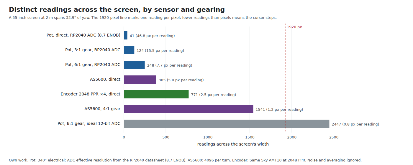
Table 2 — 2.7 Readings Across the Screen
| Sensor | Readings across the reference screen | Pixels per reading |
|---|---|---|
| Pot, direct, RP2040 ADC (8.7 ENOB) | 41 | 46.8 |
| Pot, 3:1 gear, RP2040 ADC | 124 | 15.5 |
| Pot, 6:1 gear, RP2040 ADC | 248 | 7.7 |
| AS5600, direct | 385 | 5.0 |
| AMT10 encoder, 2048 PPR, direct | 771 | 2.5 |
| AS5600, 4:1 gear | 1,541 | 1.2 |
| Pot, 6:1 gear, an ideal 12-bit converter | 2,447 | 0.8 |
The table explains the arcade’s choices at a glance. A pot on the pivot would have been unusable through an 8-bit converter of the period; a geared pot through a dedicated converter was good enough for a low-resolution raster. The last row is the theoretical ceiling of a geared pot and is never reached, because its linearity (0.5 % of track, §2.2) and its noise, not the converter, then set the limit.
2.8 The Tangent Law and Calibration
The aim point on a flat screen is x = D·tan θ from the foot of the pivot (Volume 1, §1.4). A calibration that stores two or three angle readings and maps angle to screen position along straight lines between them is exact at the calibration points and wrong between them.
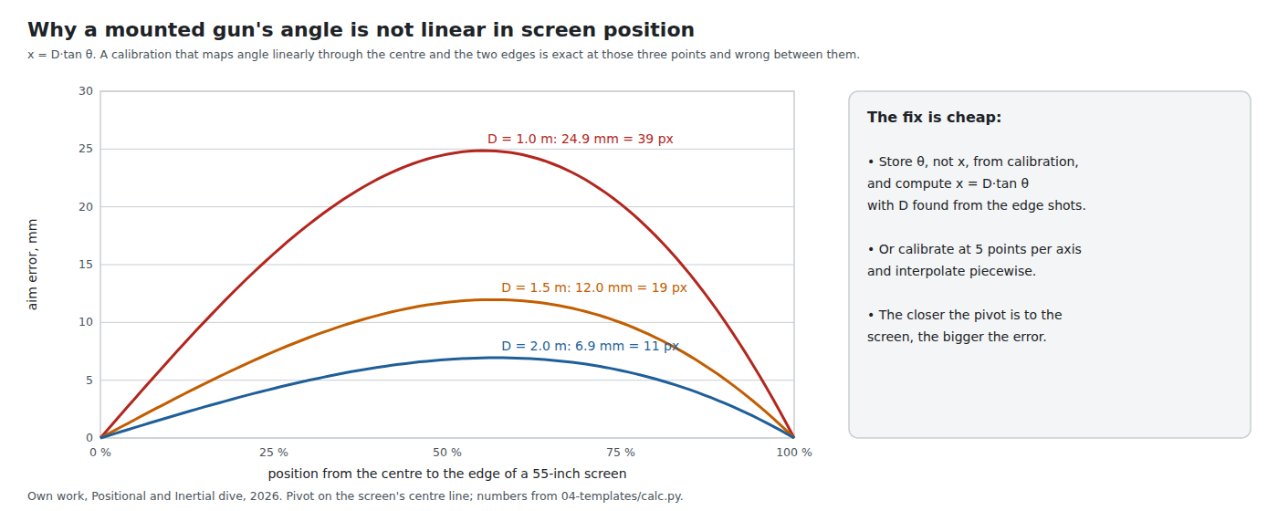
At the reference 2 m the error peaks at 6.9 mm (11 pixels) a little beyond the quarter point; at 1 m it is 24.9 mm (39 pixels). The fix costs nothing: either store the calibration as angles and compute x = D·tan(θ − θ₀) with D solved from the edge shots, or calibrate at five points per axis and interpolate. Terminator 2’s three targets — top left, centre, bottom right (Arcade Light Guns, Volume 3) — give each axis exactly three points. That is enough for an offset, a scale and the asymmetry of an off-centre pivot, and not enough to bend the line.
2.9 Why This, and Why Not the Others
This project’s gun is handheld, so a mount is not on its build path. A mount would be for a cabinet or a fixed “turret” gun in a later build, and the choice is recorded here so it is not re-derived then.
Criteria: at least one reading per two or three pixels across a 1080p screen at 2 m; no wear in daily use; absolute at power-up; few MCU pins; a calibration the firmware can do in software.
Table 3 — 2.9 Why This, and Why Not the Others
| Candidate | Readings across screen | Wear | Absolute | Pins (two axes) | Verdict |
|---|---|---|---|---|---|
| AS5600L, direct on each pivot | 385 | none | yes | 2 (one I²C bus, two addresses) | Proposed for a mounted gun: no contact, absolute, two wires for both axes. Gear 4:1 only if 5 px steps show after filtering. |
| AS5600, direct | 385 | none | yes | 4 (fixed address: two buses) | Same sensor; loses on pins. |
| Conductive-plastic pot, geared 6:1, RP2040 ADC | 248 | wiper wear, 5 M cycles ÷ 6 | yes | 2 ADC pins (of 3) | The arcade answer; loses on wear, resolution and the Pico’s scarce ADC pins. |
| Pot, direct, RP2040 ADC | 41 | wiper wear | yes | 2 ADC pins | Unusable at 1080p without heavy averaging. |
| AMT10 encoder, 2048 PPR | 771 | none (capacitive) | no: needs homing | 4 + PIO | Best resolution without gears; loses on homing and pins. |
Nothing here has been bought or tested; the pick is a proposal for the decision log.
2.10 Bench Checks
- Noise at rest. Lock the gun and log each axis. The spread is the floor any filter starts from.
- Linearity. Sweep against a reference — a laser on the gun and marks on a wall — and plot reported against true. A smooth curve is magnet offset or tangent law and calibrates out; steps are a worn track or a cracked gear tooth.
- Backlash. Approach the same mark from each side; the difference is the dead band.
2.11 What Could Not Be Verified
- The Bourns 6639 series’ rotational life and linearity: the data sheet returned HTTP 403 on 2026-10-19; only the distributor’s electrical-rotation figure is used.
- Why Space Gun’s bracket carries a tension spring. Anti-backlash loading is the likely reason; the manual does not say.
- The arcade boards’ converters other than Taito’s ADC0808 (named in MAME’s notes quoted in Arcade Light Guns, Volume 3; the ADC0808 is an 8-bit part).
Sources
Footnotes
-
Bourns 6639S series, distributor listing (chipdip.ru, 6639S-1-502; DigiKey 6639S-1-103), electrical rotation 340°, read 2026-10-19. The Bourns data sheet (https://www.bourns.com/docs/Product-Datasheets/6639.pdf) returned HTTP 403. ↩
-
TT Electronics, “6173” potentiometer series product page, https://www.ttelectronics.com/products/passive-components/potentiometers/6173/, read 2026-10-19. ↩
-
ams OSRAM, AS5600 Position Sensor datasheet v1-06 (2018), hosted by Infineon with a rebranding notice, https://www.infineon.com/assets/row/public/documents/24/49/infineon-as5600-datasheet-en.pdf, read 2026-10-19. Range quote from the ZPOS/MPOS/MANG register description; burn limit from the BURN_ANGLE command description. ↩
-
ams OSRAM, AS5600L datasheet, hosted by Infineon, https://www.infineon.com/assets/row/public/documents/24/49/infineon-as5600l-datasheet-en.pdf, read 2026-10-19. ↩
-
Same Sky (formerly CUI Devices), AMT10 Series Modular Incremental Encoder data sheet, https://www.sameskydevices.com/product/resource/amt10.pdf, read 2026-10-19. ↩
Comments (0)