Positional and Inertial Aiming · Volume 3
Gyroscopes, Accelerometers and Magnetometers — What the Datasheets Say, in Pixels
How a MEMS gyroscope senses rotation; three current six-axis parts compared from their datasheets; why bias, not noise, is what drifts, worked through in pixels on a 55-inch screen; what an accelerometer can and cannot tell a gun; and why a magnetometer inside a gun with a 24-volt solenoid is no reference at all
3.1 What an IMU Is
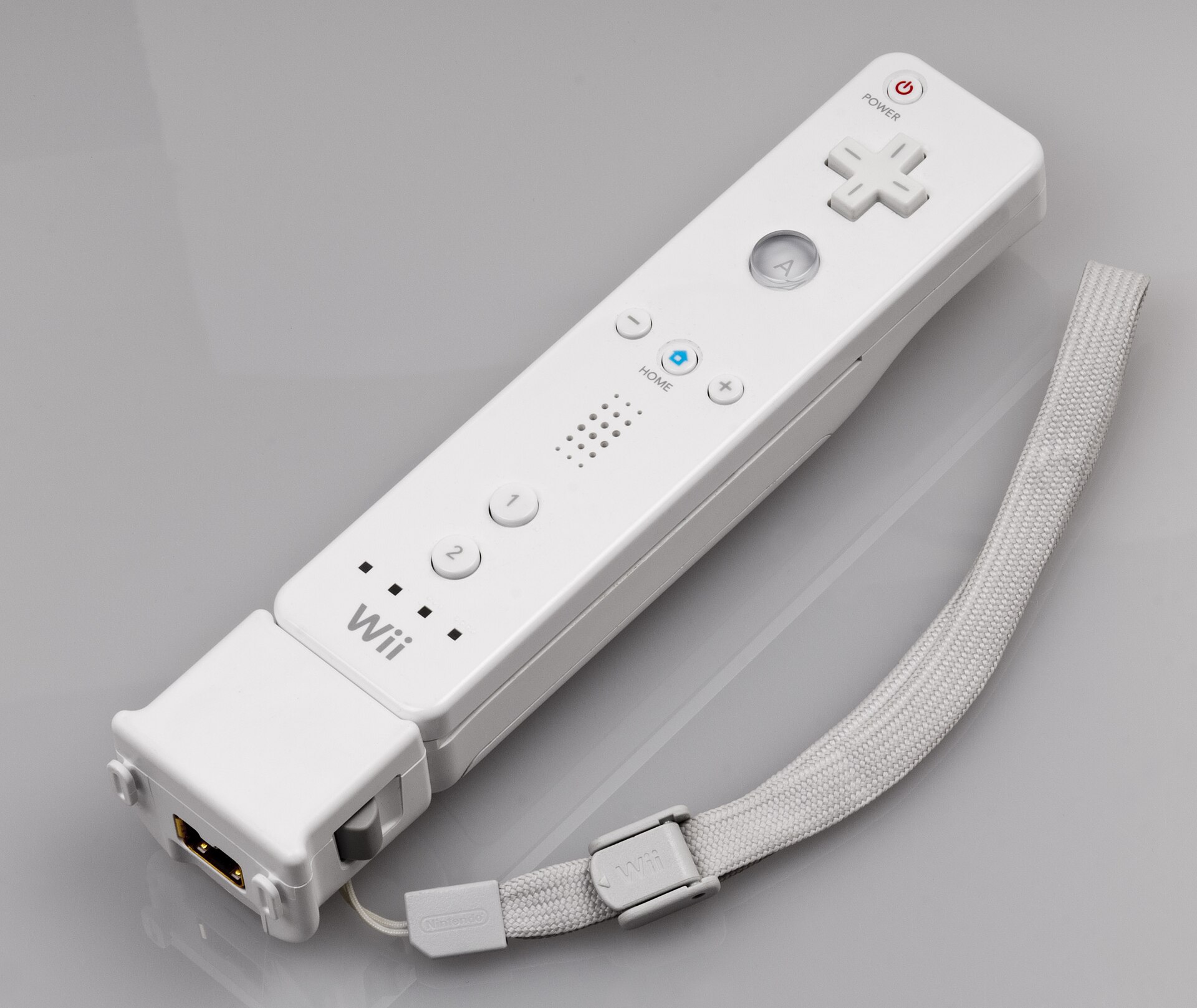
An inertial measurement unit, in the sense the parts below are sold, is a three-axis gyroscope and a three-axis accelerometer on one die or in one package, with converters, digital filters, a FIFO and a serial interface. A “nine-axis” IMU adds a three-axis magnetometer. A “fusion” part — Bosch’s BNO055 and CEVA’s BNO08x are the common ones — adds a microcontroller running an orientation filter and reports a quaternion instead of raw rates (Volume 4, §4.6).
For a light gun the interesting sensor is the gyroscope. It is the only one of the three that measures yaw — the left-right turn across the screen — at all quickly, and it is also the one that drifts.
3.2 How a MEMS Gyroscope Senses Rotation
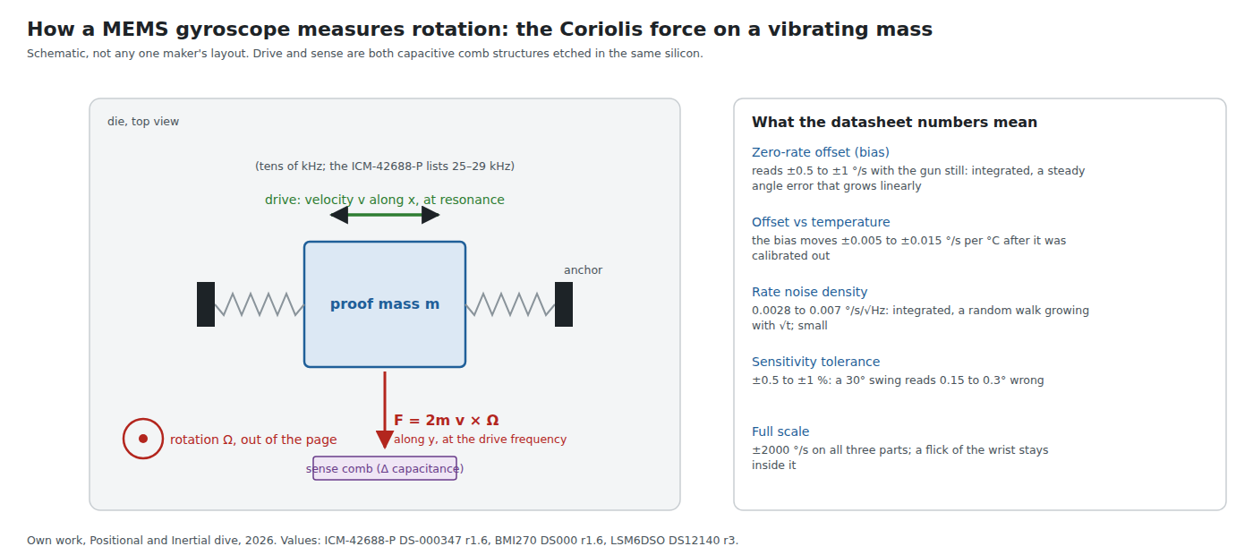
A MEMS gyroscope does not spin. A small silicon proof mass is driven to oscillate along one axis at its mechanical resonance — TDK lists the ICM-42688-P’s gyroscope mechanical frequencies as 25 to 29 kHz.1 When the die rotates, the Coriolis force on the moving mass, F = 2m v × Ω, pushes it at right angles to its drive motion, in phase with the drive velocity. Capacitive sense electrodes measure that displacement and a demodulator at the drive frequency turns it into a rate.
Everything that makes a gyroscope drift comes from that chain. Any mechanical coupling between drive and sense motion, any electrical leakage of the drive into the sense path, appears as a rate when nothing is turning: the zero-rate output, or bias. It depends on temperature because the mechanical and electrical couplings do. The random part — thermal noise in the mass and the electronics — appears as rate noise.
3.3 Three Datasheets Side by Side
Three six-axis parts current in October 2026 cover the hobby market’s options: TDK InvenSense’s ICM-42688-P, Bosch Sensortec’s BMI270, and ST’s LSM6DSO (and its machine-learning-core sibling the LSM6DSOX, whose gyroscope figures are identical).1234 All figures are the datasheets’ typical values.
Table 1 — 3.3 Three Datasheets Side by Side
| Gyroscope | ICM-42688-P | BMI270 | LSM6DSO / DSOX |
|---|---|---|---|
| Full scale | ±15.6 to ±2000 °/s | ±125 to ±2000 °/s | ±125 to ±2000 °/s |
| Zero-rate offset, 25 °C | ±0.5 °/s | ±0.5 °/s | ±1 °/s |
| Offset change with temperature | ±0.005 °/s/°C (0 to 70 °C) | ±0.015 °/s/K | ±0.010 °/s/°C |
| Rate noise density | 0.0028 °/s/√Hz | 0.007 °/s/√Hz | 0.0038 °/s/√Hz |
| Sensitivity tolerance | ±0.5 % | not compared here | ±1 % |
| Output data rate | 12.5 Hz to 32 kHz | 25 Hz to 6.4 kHz | 12.5 Hz to 6.66 kHz |
| Accelerometer | |||
| Zero-g offset | ±20 mg | — | ±20 mg |
| Offset with temperature | ±0.15 mg/°C | ±0.25 mg/K | ±0.1 mg/°C |
| Noise density | 70 µg/√Hz | — | 70 µg/√Hz (±2 g) to 110 µg/√Hz (±16 g) |
| Interface and power | |||
| I²C | to 1 MHz | 100 kHz, 400 kHz, 1 MHz (Fm+) | 400 kHz (DSOX timing table also lists Fm+, “validated by characterization”) |
| SPI | to 24 MHz | yes | yes |
| I²C address | 0x68 / 0x69 | 0x68 / 0x69 | 0x6A / 0x6B |
| FIFO | 2 kB | 2 kB | 9 kB, compressible |
| Current, gyro + accel running | 0.88 mA (low-noise mode) | 685 µA typ. | 0.55 mA (high-performance) |
| Start-up quirk | gyro start-up 30 ms | 8 kB configuration file must be written at every power-up | — |
(The BMI270’s accelerometer offset and noise are in its Table 2; only the temperature coefficient is used here.)
Three things stand out for a gun:
- The ICM-42688-P’s offset tempco is a third of the BMI270’s and half the LSM6DSO’s. Section 3.5 shows that this is the number that decides how far a calibrated gyro drifts.
- The BMI270 cannot start without its configuration blob. Its datasheet requires the host to “Burst write 8 kB initialization data to Register INIT_DATA” at every power-up; at 400 kHz that is 184 ms of bus time and 8 kB of the host’s flash. Bosch’s wearable feature engine (step counting, wrist gestures) lives there; a light gun needs none of it.
- The LSM6DSO’s I²C is a 400 kHz part on its datasheet, and its 9 kB FIFO is the largest of the three. ST’s finite-state machines and (on the DSOX) machine-learning core can detect gestures on the chip without waking the host.
3.4 Bias, Noise and Scale, Integrated
The firmware turns rate into angle by summing samples: θ = Σ ω·Δt. Each error in ω becomes a different kind of error in θ.
- A constant bias b becomes an angle error b·t, growing linearly. At 0.5 °/s it is half a degree after one second.
- White rate noise of density N becomes an angle random walk with standard deviation N·√t. With N in °/s/√Hz, N·√t comes out in degrees; the ICM-42688-P’s 0.0028 °/s/√Hz is 0.0028° after one second and 0.022° after a minute. Multiplied by 60 it is the familiar “angle random walk” unit: 0.17 °/√h.
- A scale-factor error s makes every real rotation read s too large or small: a 30° swing at 0.5 % reads 0.15° wrong. It does not grow with time, only with how far the gun has turned since the last absolute fix.
- Bias instability — the slow wandering of the bias over seconds to minutes at constant temperature — is the figure navigation-grade gyroscope datasheets lead with. None of the three consumer datasheets above specifies it, so it is not used here.
3.5 Drift in Pixels
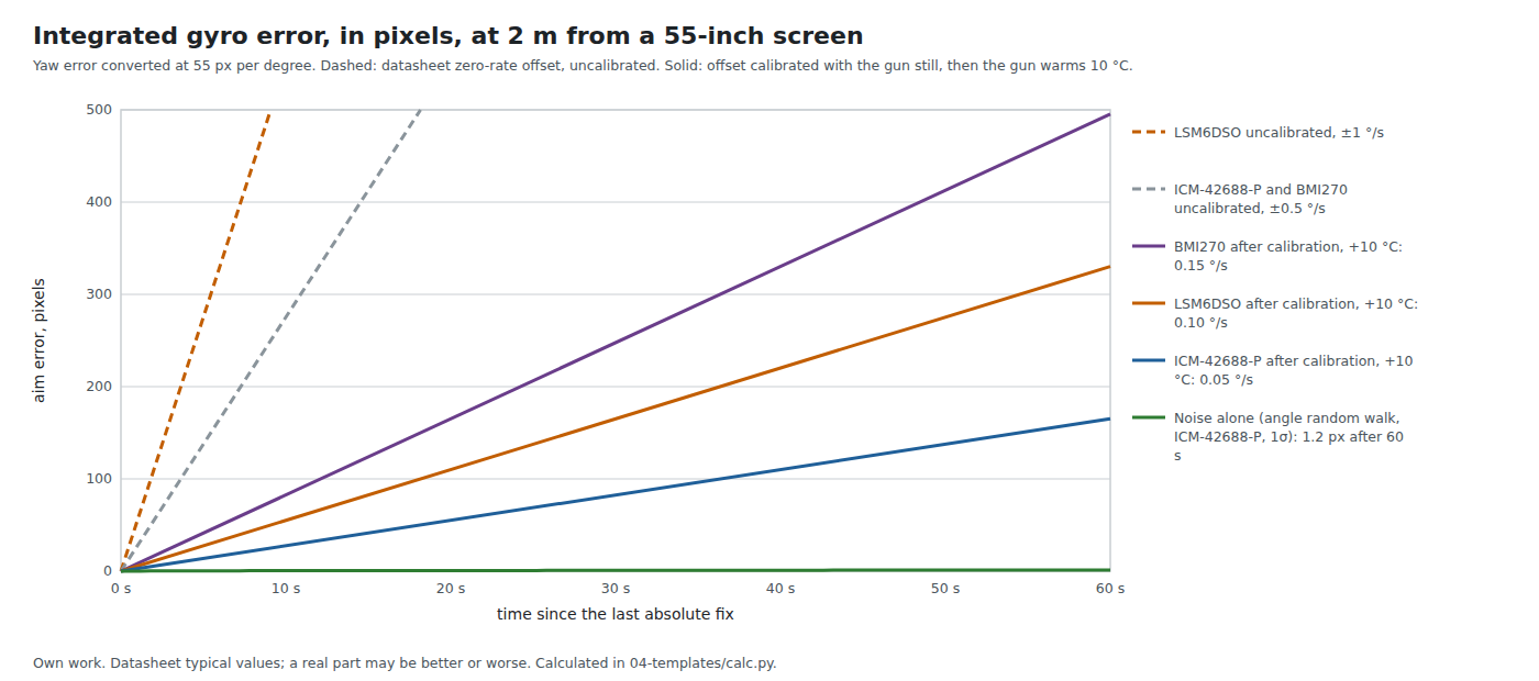
The reference room of Volume 1 converts angle at 55 pixels per degree. With that conversion the datasheets give:
Table 2 — The reference room of [Volume 1](/light-guns/sensing-and-aiming/positional-and-inertial/vol-1/) converts angle at 55 pixels per degree. With that conversion the datasheets give
| Case | ICM-42688-P | BMI270 | LSM6DSO |
|---|---|---|---|
| Uncalibrated, after 1 s | 28 px | 28 px | 55 px |
| Uncalibrated, after 10 s | 275 px | 275 px | 550 px |
| Calibrated at rest, then +10 °C, after 10 s | 28 px | 83 px | 55 px |
| Calibrated at rest, then +10 °C, after 60 s | 165 px | 495 px | 330 px |
| Noise only (1σ), after 60 s | 1.2 px | 3.0 px | 1.6 px |
(From 04-templates/calc.py; the offsets are the datasheets’ typical figures, a real part may be better or worse.)
Four conclusions follow, and they are the core of this dive.
- Uncalibrated, no MEMS gyroscope can aim. A typical part is a quarter of a screen out within ten seconds.
- After a calibration at rest, temperature is the enemy. A gun warms in the hand, and this one carries a solenoid that dissipates watts in short pulses (Solenoid Recoil). Ten degrees is not an extreme assumption for an IMU mounted near the driver stage.
- Noise is not the problem. The angle random walk of all three parts stays within a few pixels for a minute. A better gyroscope for a gun is one with a lower offset tempco, not lower noise.
- Even the best calibrated case is unusable as a sole aiming sensor for more than a few seconds — and that is before the translation error of Volume 1, §1.5, which a gyroscope cannot see at all. A gyroscope in a light gun can only ever be an assistant to an absolute fix. Volume 4 is about how it assists.
3.6 Calibrating the Bias
At rest. Average the gyroscope for a second or two while the gun is still and subtract the result. The WiiBrew documentation advises exactly this for the MotionPlus: “it is best to calibrate for a few seconds every time you start, to get the actual zero values.”5 Detecting “still” is easy from the gyroscope itself (rate below a threshold) and the accelerometer (magnitude close to 1 g and steady). The averaging time is set by noise: with the ICM-42688-P’s 0.0028 °/s/√Hz, a one-second average estimates the bias to about 0.003 °/s, well under the temperature effect.
With temperature. All three parts carry a temperature sensor. Logging bias against die temperature on the bench, over the range the gun reaches, gives a correction table; the residual is then the part’s repeatability rather than its full tempco. This is the cheapest single improvement for a gun with a solenoid in it.
On line, against an absolute reference. Whenever an absolute measurement exists — gravity for pitch and roll, the camera for yaw and pitch — the difference between what the gyroscope integrated and what the reference saw over the same interval is a measurement of the bias. A fusion filter with an integral term learns it continuously (Mahony’s filter, Volume 4, §4.3). For a camera gun this is the important case: the camera’s 209 position fixes a second (Open-Source Firmware, Volume 2) keep the gyroscope’s yaw bias calibrated for as long as the markers are in view, so the gyroscope enters any dropout freshly corrected.
Jibb Smart’s warning from the gyro-aiming community applies to all automatic schemes: “Auto-calibration will get things wrong at crucial times.” A calibration that runs while the player is holding the gun steady on a target, and mistakes a slow deliberate track for bias, removes real motion. The on-line form against a camera does not have this failure, because the camera sees the real motion too.
3.7 What an Accelerometer Can Tell a Gun
Tilt, when still. At rest the accelerometer measures gravity, so pitch and roll follow from its three components. With 70 µg/√Hz of noise in a 50 Hz bandwidth the roll estimate is good to about 0.03° rms; the ±20 mg zero-g offset tolerance is worth up to 1.15° before calibration. For a camera gun the camera already measures roll from the four markers (IR Point Tracking, Volume 3 shows the four-point solution staying exact with the camera rolled 15°), so the accelerometer adds roll only when the markers are out of view.
Gestures. A sharp shake, the gun pointed at the floor or the ceiling, a flick upward: all are large, unambiguous accelerometer signatures, and the LSM6DSO’s on-chip state machines exist to detect such things. Volume 6 uses the gun-pointed-down gesture as a reload.
Not position. Integrating acceleration twice turns a constant error into a position error ½·a·t²:
Table 3 — Not position. Integrating acceleration twice turns a constant error into a position error ½·a·t²
| Accelerometer bias | after 0.25 s | after 1 s | after 2 s |
|---|---|---|---|
| 1 mg | 0.3 mm | 4.9 mm | 19.6 mm |
| 5 mg | 1.5 mm | 24.5 mm | 98 mm |
| 20 mg (the zero-g tolerance) | 6.1 mm | 98 mm | 392 mm |
And the bias is not only the sensor’s: a tilt estimate wrong by 0.1° leaks 1.75 mg of gravity into the horizontal axis, 0.5° leaks 8.7 mg. Position from an accelerometer is good for a quarter of a second at best, which is why every system that needs position (Volume 5) measures it with something else.
During recoil. A solenoid kick is a large, brief acceleration. The bench work in Solenoid Recoil, Volume 6 measures the impact with an analogue ADXL1002 because a ±16 g IMU “clips and samples too slowly” to resolve a 0.1 to 1 ms impact. That is true for measuring the impact. For detecting that a kick happened, and for gating the fusion filter while it does (Volume 6), a ±16 g IMU sampling at a few kilohertz is enough; the research note behind that volume estimated the gun body’s acceleration at around 5 g, an estimate still waiting for a bench number.
3.8 Magnetometers Indoors, and Next to a Solenoid
A magnetometer gives heading — yaw — against magnetic north, which would make it the absolute yaw reference a gyroscope lacks. Sony’s PlayStation Move carries one; Sony’s specification as reprinted by MCV in March 2010 lists a “Three-axis gyroscope”, a “Three-axis accelerometer” and a terrestrial magnetic field sensor (spelt “megnetic” in the reprint).6
Indoors it is a poor reference. Heading is computed from the horizontal component of the Earth’s field, B_h, and any disturbing field B_d at right angles to it moves the computed heading by atan(B_d / B_h):
Table 4 — Indoors it is a poor reference. Heading is computed from the horizontal component of the Earth's field, Bh, and any disturbing field Bd at right angles to it moves the computed heading by atan(Bd / Bh)
| Horizontal field | 1 µT disturbance | 3 µT | 10 µT |
|---|---|---|---|
| 15 µT | 3.8° | 11.3° | 33.7° |
| 20 µT | 2.9° | 8.5° | 26.6° |
| 25 µT | 2.3° | 6.8° | 21.8° |
The horizontal component depends on latitude; for a given room it can be read from NOAA’s World Magnetic Model calculator. The point of the table is the ratio: a disturbance of a few per cent of the Earth’s field is degrees of heading, and a degree is 55 pixels. Steel studs, ductwork and rebar make indoor fields vary from place to place — the indoor-positioning literature uses those anomalies as fingerprints precisely because they are large and local — and a television’s speakers carry permanent magnets.
The decisive argument for this build is inside the gun. The recoil stage is a solenoid with a steel plunger, pulsed at amps on every shot. A magnetometer anywhere near it will see a field that moves with the plunger and the coil current, and a fixed steel mass that distorts the Earth’s field around it. Hard-iron and soft-iron calibration can take out the fixed part; nothing takes out a coil pulsing at the moment the player is aiming. This dive does not consider a magnetometer as a yaw reference for the gun. The camera is the yaw reference.
3.9 A Worked Historical Example: the Wii MotionPlus
Nintendo’s MotionPlus is the clearest published example of a gyroscope added to an infrared pointer. Its history — announced in July 2008, shipped with Wii Sports Resort — belongs to History of Light Guns, Volume 7; its engineering, as documented by the community, belongs here.
- The sensors. WiiBrew identifies “A dual-axis gyro by InvenSense, the IDG-600 (pitch and roll)” and “a single-axis gyro by EPSON TOYOCOM labelled X3500W (yaw)”.5 InvenSense’s own release of 15 July 2008 announced mass-production shipments of the IDG-600 to Nintendo, and quoted Nintendo’s Genyo Takeda on the choice: its “ability to measure large dynamic motions”.7
- Two ranges. Each axis reports a slow/fast flag; WiiBrew’s scale factors make the slow range about 440 °/s and the fast range about 2000 °/s, citing InvenSense for the two figures. A wrist flick exceeds the first and not the second, the same reason the modern parts above go to ±2000 °/s.
- Calibration at start-up. The resting zero is “about 0x1F7F (8,063)”, and the advice is to calibrate “for a few seconds every time you start”.
- Drift, corrected for two axes only. “It will drift a little, so you should reset the matrix’s pitch and roll (but not yaw)” from the accelerometers whenever the remote is still. For yaw, the Wii had the Sensor Bar and its camera — when the remote pointed at the screen.
That last point is the whole architecture of the hybrid in Volume 4: a gyroscope for fast motion, gravity for down, and an optical fix for the axis nothing else can anchor.
3.10 What Could Not Be Verified
- The ICM-42688-P figures are from datasheet revision 1.6 (June 2021); TDK lists a revision 1.8 (July 2023) that could not be downloaded. The gyroscope specifications are not expected to have changed, but that is not confirmed.
- Bias instability for any of the three parts: none of the datasheets specifies it.
- The Epson X3500W yaw gyroscope’s specification: WiiBrew says it is “currently unknown”.
- Whether the later MotionPlus used the IDG-650, as secondary sources say. Not confirmed from a primary source.
- How far a solenoid’s field reaches a magnetometer at a given spacing in this gun: not measured; the argument in §3.8 is qualitative.
Sources
Footnotes
-
TDK InvenSense, ICM-42688-P Datasheet, DS-000347 revision 1.6, 20 June 2021, §3.1–3.3 and the I²C address table, https://product.tdk.com/system/files/dam/doc/product/sensor/mortion-inertial/imu/data_sheet/ds-000347-icm-42688-p-v1.6.pdf, read 2026-10-19. ↩ ↩2
-
Bosch Sensortec, BMI270 Data Sheet, BST-BMI270-DS000 revision 1.6, March 2026, Tables 2 and 3, §4 (initialization) and §6.5 (I²C), https://www.bosch-sensortec.com/media/boschsensortec/downloads/datasheets/bst-bmi270-ds000.pdf, read 2026-10-19. ↩
-
STMicroelectronics, LSM6DSO, DS12140 revision 3, June 2024, Table 2 and §5 (digital interfaces), https://www.st.com/resource/en/datasheet/lsm6dso.pdf, read 2026-10-19. ↩
-
STMicroelectronics, LSM6DSOX, DS12814 revision 4, June 2024, mechanical characteristics and I²C timing, https://www.st.com/resource/en/datasheet/lsm6dsox.pdf, read 2026-10-19. ↩
-
WiiBrew wiki, “Wiimote/Extension Controllers/Wii Motion Plus”, https://wiibrew.org/wiki/Wiimote/Extension_Controllers/Wii_Motion_Plus, read 2026-10-19 (community documentation, secondary). ↩ ↩2
-
MCV, “Full tech specs: PlayStation Move”, 11 March 2010, reproducing Sony’s specification, https://www.mcvuk.com/development/full-tech-specs-playstation-move, read 2026-10-19 (secondary). ↩
-
Nintendo World Report, “Wii MotionPlus Technology Provider Reveals the Guts Behind the Device”, 17 July 2008, reporting InvenSense’s release of 15 July 2008, https://www.nintendoworldreport.com/news/16410/wii-motionplus-technology-provider-reveals-the-guts-behind-the-device, read 2026-10-19. ↩
Comments (0)