Experimental Sensing · Volume 4
Coded Frames on a Modern Display — The Zapper Generalised, and Its Ceiling
Flash a short sequence of Gray-code patterns and a photodiode can tell where on any screen it is pointing. The projector researchers who did it in 2004, why a gun at two metres is a harder problem than a sensor on the screen, how phase-shifted patterns get past the optics, and what each shot would cost in frames and flicker
4.1 The Idea
The Zapper asked the screen a yes-or-no question: on the frame the game drew a white box over each target, did the gun see light? CRT Timing, Volume 7, §7.6 generalised it. Draw a sequence of black-and-white patterns whose on/off history is different at every point of the screen, and the photodiode’s sequence of readings is its position. With binary or Gray-code stripes, a 1,920 × 1,080 picture needs 11 frames for X and 11 for Y. That volume tabulated the time per shot at 60, 240 and 480 Hz, and noted that the method needs only frame-level timing, so it survives the move from the CRT to any display that can show a frame intact. It found no light gun that does it and handed the question here.
The attraction is the hardware: a photodiode, an amplifier and a lens, no camera and no bar. The rest of this volume asks how much of that promise survives contact with optics and with the player.
4.2 Where It Has Been Done
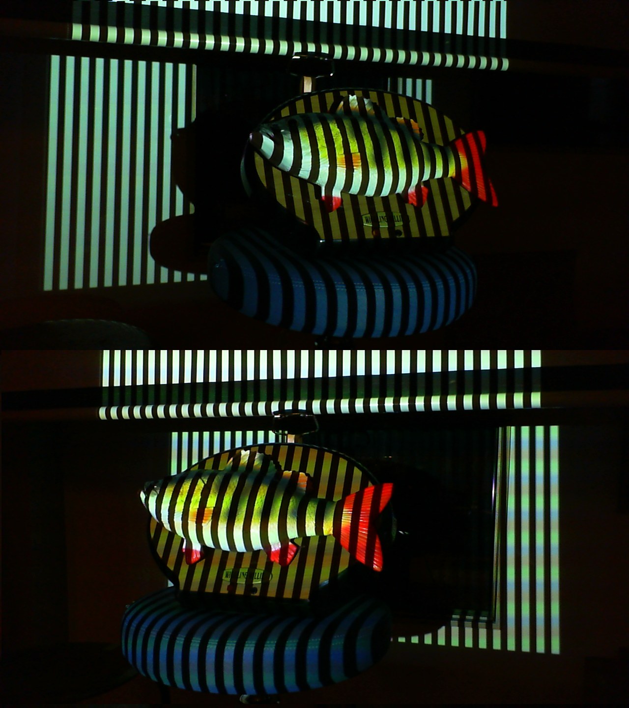
Not in a light gun, but in the closest possible relative. In 2004, Johnny Chung Lee, Paul Dietz, Dan Maynes-Aminzade, Ramesh Raskar and Scott Hudson put light sensors in the corners of a projection screen and found them by projecting Gray codes, then pre-warped the image to fit. Their UIST paper and the MERL technical report describe the method in the terms used here:
- “Each pattern consists of black-and-white stripes that divide the projection area more finely with each successive step … these images uniquely identify every pixel location.”
- “Unlike traditional binary division, the stripe boundaries in Gray-code patterns never occur at the same location … Gray-code patterns limit the error resulting from boundary events to +/- 1 pixel.”
- “Every pixel in an XGA resolution projector (1024x768) can be uniquely identified with only 20 binary patterns”, and the prototype calibrated “in less than one second”.
- Threshold set from a black and a white reference frame; and “projecting each calibration pattern followed by its inverse and then differencing the two readings … cancels out the effects of ambient lighting, but requires projecting twice as many patterns.”
A year later Jay Summet, Lee and colleagues used the same idea for tracking: a handheld surface with four sensors followed in real time at “an update rate of 12Hz”, with “a sensing package costing less than $10USD”. They also hid the patterns. With the colour wheel removed from an InFocus X1 DLP projector, two colours of equal apparent brightness reached a light sensor as a 180 Hz and a 360 Hz signal, so a pattern “appears to be solid gray to a human observer but in fact contains rapidly changing location data detectable by a light sensor.”
So coded-frame position sensing is a published prototype, labelled here as a prototype of a related task: the sensor was on the screen, a millimetre from the pixels it decoded.
4.3 The Gun’s Problem: It Sees a Patch
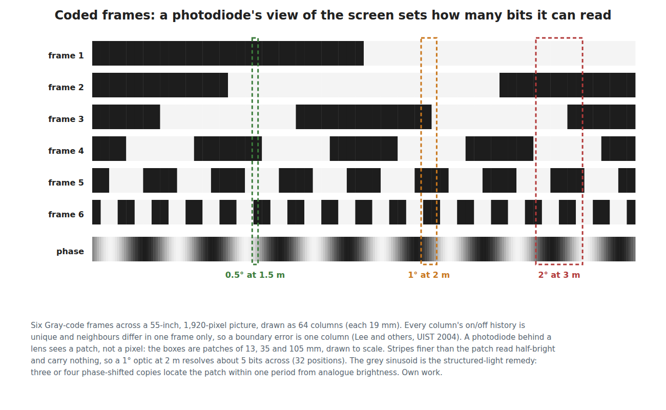
A sensor on the screen sees one pixel. A photodiode in a gun two metres away sees whatever patch of screen its optics admit, and averages it. A stripe finer than the patch reads as half-bright, the same in its on and off phases, and carries nothing. The resolution is set by the gun’s field of view, not by the screen.
On a 55-inch 1080p set, pixels are 0.634 mm apart. From 04-templates/calc_experimental.py:
Table 1 — On a 55-inch 1080p set, pixels are 0.634 mm apart. From 04-templates/calcexperimental.py
| Photodiode field of view | Distance | Patch on the screen | Gray bits it can resolve across | Up |
|---|---|---|---|---|
| 0.5° | 1.5 m | 13 mm (21 px) | 6.5 | 5.7 |
| 0.5° | 3 m | 26 mm (41 px) | 5.5 | 4.7 |
| 1° | 2 m | 35 mm (55 px) | 5.1 | 4.3 |
| 2° | 3 m | 105 mm (165 px) | 3.5 | 2.7 |
A one-degree optic at 2 m distinguishes about 32 positions across a 55-inch picture and 20 up it. A narrower field resolves more but collects less: the light from a uniformly lit patch scales with the square of the field angle, so half a degree gathers a quarter of what one degree does, against a room that has not got any darker. The CRT guns had the same trade, and solved it with a CRT’s enormous peak brightness and microsecond timing (CRT Timing, Volume 3); a coded-frame gun on an LCD has neither.
4.4 Getting Past the Patch
Structured-light scanners solve the same problem, a camera pixel larger than the finest stripe, with phase shifting. After the Gray codes have located the patch to within one coarse stripe, the screen shows a sinusoidal brightness pattern a few patches wide, three or four times, each shifted by a fraction of its period. The photodiode’s analogue readings of the three or four versions give the phase of the sinusoid at the patch’s centre, which places the patch within the period far more finely than its width. How finely depends on the signal-to-noise ratio of the readings and on the display’s tone curve, which must be measured, so it is not estimated here.
The sequence for one shot then looks like this:
Table 2 — The sequence for one shot then looks like this
| Scheme | Frames |
|---|---|
| 5 Gray bits across + 5 up + 3 phase steps each way + black and white references | 18 |
| Full 11 + 11 Gray bits + references (CRT Timing’s case) | 24 |
| 5 + 5 Gray and 3 + 3 phase, each followed by its inverse for ambient rejection | 32 |
4.5 What Each Shot Costs
Table 3 — 4.5 What Each Shot Costs
| Refresh rate | 18 frames | 24 frames | 32 frames |
|---|---|---|---|
| 60 Hz | 300 ms | 400 ms | 533 ms |
| 120 Hz | 150 ms | 200 ms | 267 ms |
| 144 Hz | 125 ms | 167 ms | 222 ms |
| 240 Hz | 75 ms | 100 ms | 133 ms |
| 480 Hz | 38 ms | 50 ms | 67 ms |
Each figure is before the display’s own lag, which CRT Timing, Volume 7, §7.3 puts at one to six frames on typical sets and which pipelining absorbs once, not per frame. Four costs follow.
- It answers per shot, not continuously. A camera gun reports a cursor 209 times a second. A coded-frame gun tells the game where it was when the trigger was pulled, a few hundred milliseconds later on an ordinary television. That suits a Duck Hunt-style shooting gallery and nothing with a cursor or a moving reticle.
- The player sees it. Every shot flashes a sequence of full-screen stripes. At 480 Hz the burst is brief; at 60 Hz it is a third of a second of strobing pattern. A full-screen patterned flash on every shot is also the kind of content photosensitivity guidance exists for; it is not assessed here.
- The game must draw it. As with border tracking, every platform needs host software that inserts the frames, and every video path between the game and the screen must pass them intact, with motion smoothing off (Border Tracking, Volume 8 sets out what that demands).
- Pixel response. An LCD that takes 5 to 17 ms to rise (CRT Timing, Volume 7, §7.3) blurs one pattern into the next at high refresh rates; an OLED does not.
4.6 Could the Patterns Be Hidden?
Summet and Lee hid theirs by exploiting how a single-chip DLP projector paints colours in sequence. A television does not do that, so the trick does not transfer. The general alternative is to draw each pattern and then its complement in the next frame, at a rate above the eye’s flicker fusion, so the eye sees the average and a fast sensor sees the difference. That has been done for cameras reading on-screen markers (Volume 7, §7.4), but for a single photodiode it needs every pattern twice and a display fast enough that the pair fuses, which multiplies the shot times above.
4.7 The Bench Test
The experiment is cheap and could be run with parts the lab already has or has proposed.
- Display. A monitor at 60 Hz, and at 144 Hz or more if one is available, showing full-screen Gray-code and phase patterns from a short Python script, each frame announced on a serial line or by a corner marker the photodiode cannot see.
- Sensor. The photodiode and transimpedance amplifier proposed for the CRT bench, a Vishay BPW34 into a TI OPA380 (CRT Timing decision row CT-1), or the BPV10NF proposed for the infrared bench (P-IRT2), behind a short-focal-length lens with an aperture at its focus to set the field to 1°, in a printed tube.
- Measurement. The ADP3450’s oscilloscope records the amplifier output through each sequence; a script decodes the Gray bits and the phase. At 1, 2 and 3 m, aim at marked points and compare the decoded position with the true one. The first frame of each sequence also measures the display’s lag.
4.8 Why Try This, and Why Not the Others
What it buys the build. Nothing the reference gun needs. It would make the cheapest possible gun, a photodiode and a lens, work on any display, but only per shot, slowly, with visible flashing, with host software, and with a few tens of positions across the screen before phase stepping. The PAJ7025 reports 4,096 counts per axis 209 times a second without any of that.
What it costs. Almost nothing: a lens, a printed tube, parts already proposed, and an evening of Python.
The risk. None to the build; it is a side experiment.
Why try this, and why not the others. Try it as a demonstration that closes CRT Timing’s open question with a measurement, and as a lesson in why the light gun moved to cameras. Do not try it before the synchronised bar or the retroreflectors (Volumes 2 and 3), which could change the kit.
4.9 What Could Not Be Verified
- Any light gun using coded frames; none was found.
- The phase-step resolution achievable through a real lens on a real display.
- How visible an 18-frame burst is at each refresh rate, and its photosensitivity implications.
Sources
- J. C. Lee, P. H. Dietz, D. Maynes-Aminzade, R. Raskar, S. E. Hudson, “Automatic Projector Calibration with Embedded Light Sensors”, Proceedings of UIST 2004, pp. 123–126; MERL TR2004-036, https://merl.com/publications/docs/TR2004-036.pdf (read 2026-10-19).
- J. Summet, J. C. Lee and others, “Moveable Interactive Projected Displays Using Projector Based Tracking”, Proceedings of UIST 2005, https://faculty.cc.gatech.edu/~summetj/papers/uist05.pdf (read 2026-10-19).
- CRT Timing, Volumes 3 and 7, for the coded-frame idea, display lag and LCD rise times.
- Arithmetic:
04-templates/calc_experimental.py, output in02-inputs/calc-output.txt.
Comments (0)