Experimental Sensing · Volume 3
Retroreflectors and a Light on the Gun — Passive Targets at the Screen
Turn the bar round: put the infrared source beside the camera and four corner-cube reflectors on the bezel. Who has done it, how much light comes back, why the LEDs must sit within a few millimetres of the lens, the glint a glossy screen returns, and the industrial trick that removes it
3.1 The Idea
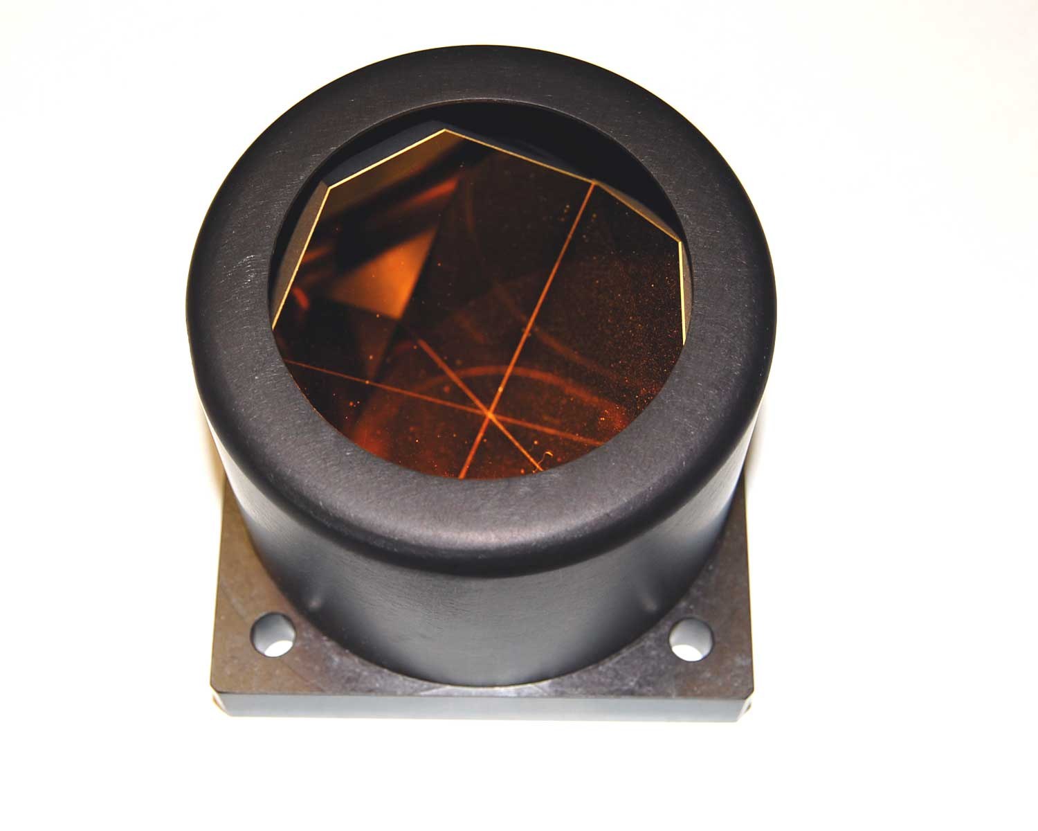
An active bar needs power at the screen: a cable to a USB port or a wall supply, a driver board and LEDs that must be matched and binned (Reference Electronics, Volume 6). A retroreflector needs nothing. It is a passive optical element that sends light back toward its source over a narrow cone, whatever angle it arrives from. Put a ring of 850 nm LEDs round the gun’s camera lens and four pieces of corner-cube sheeting at the bezel in the square layout (IR Point Tracking, Volume 3), and the camera sees four bright points exactly where an active bar’s would be. The rest of the firmware, the sort, the homography and the calibration, does not change.
For a kit, the attraction is large: stickers instead of a powered bar, nothing to plug in at the television, nothing for a customer to wire. The question is whether enough light comes back.
3.2 It Has Been Done, Nearly
The optical arrangement has a published prototype. In 2007 Johnny Chung Lee, then at Carnegie Mellon, put retroreflective tape on his fingertips and an infrared LED array behind a Wii Remote: “Using an LED array and some reflective tape, you can use the infrared camera in the Wii remote to track objects, like your fingers, in 2D space … The Wiimote can track upto 4 points simultaneously.” That is a Wii-class blob camera, its own illuminator, and passive reflectors, at arm’s length. It is not a light gun, and Lee’s page gives no ranges or LED counts; it shows the method works with this class of sensor.
PixArt designed the PAJ7025 for it as well. Its 2016 general datasheet says that “the moving object(s) could have active IR light source or passive IR reflector”, and the same document rates the sensor’s two LED pins as drivers, “IR-TX LED driving pin is 130~170mA”, alongside the frame-subtraction register (Volume 2, §2.2). A sensor that drives its own LED, subtracts LED-off frames, and expects passive reflectors is a sensor built for exactly this arrangement. With retroreflectors, the light source travels with the camera, so the sensor’s own frame subtraction can work as PixArt intended, with no synchronisation problem to solve.
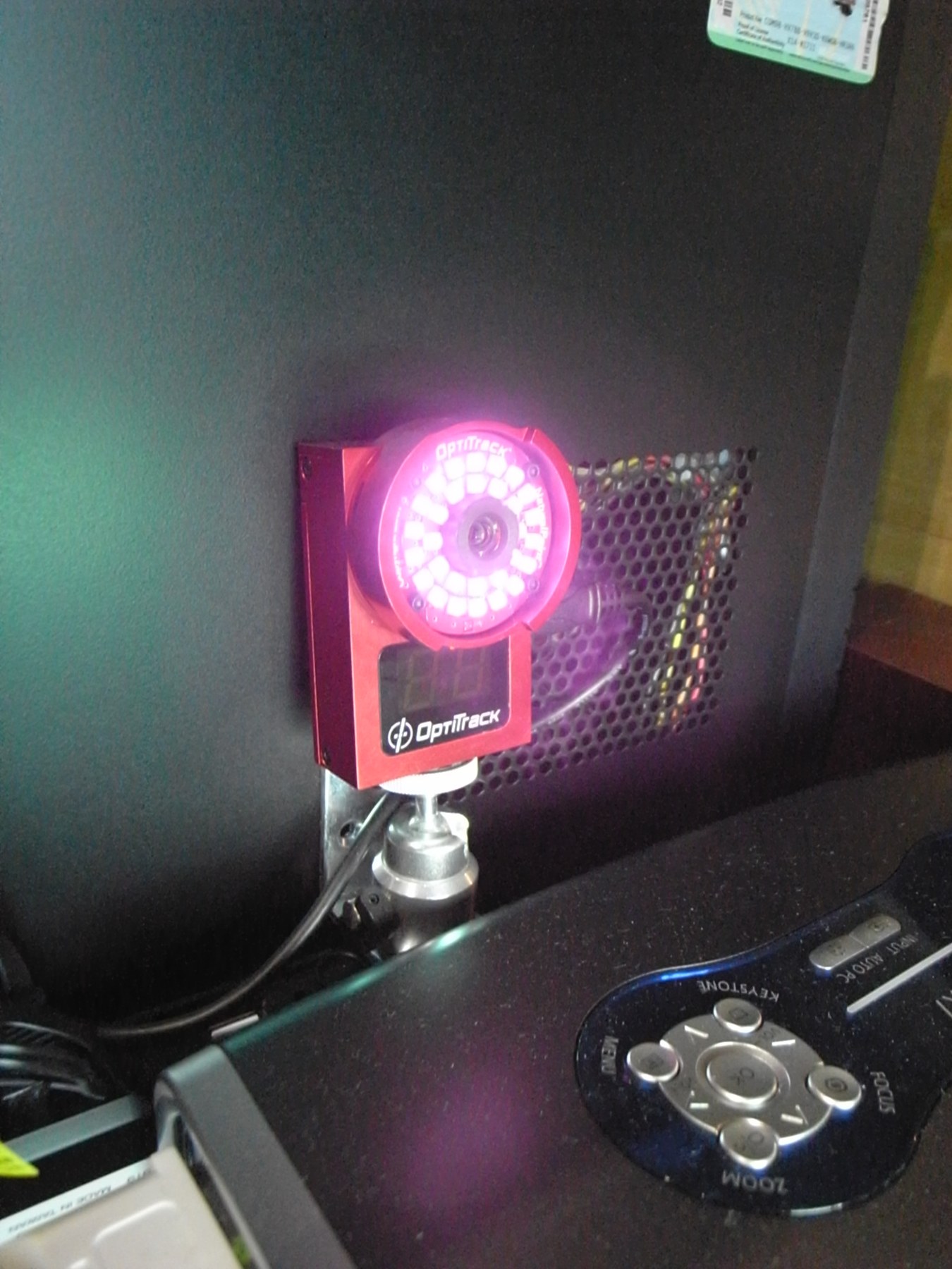
Optical motion capture is the industrial version: cameras ringed with infrared LEDs, as in the photograph above, tracking passive reflective markers.
3.3 How Much a Corner Cube Returns
Road-sign sheeting is the cheapest source of corner cubes, and its makers publish exactly the figure needed. The coefficient of retroreflection, R_A, is the luminous intensity sent back per unit illuminance on the sheet per unit area, in candelas per lux per square metre. It depends on two angles: the entrance angle (how far off its face the light arrives) and the observation angle (the angle at the sheet between the light source and the observer). For a gun, the observation angle is simply the LEDs’ offset from the lens divided by the distance.
3M’s October 2020 bulletin for Diamond Grade DG³ Series 4090, a “full cube retroreflective sheeting”, gives for white at 5° entrance:
Table 1 — 3M's October 2020 bulletin for Diamond Grade DG³ Series 4090, a "full cube retroreflective sheeting", gives for white at 5° entrance
| Observation angle | 0.1° | 0.2° | 0.33° | 0.5° | 1.0° | 1.5° |
|---|---|---|---|---|---|---|
| R_A, cd·lx⁻¹·m⁻² | 850 | 625 | 425 | 420 | 120 | 15 |
At 30° entrance the 0.2° figure falls from 625 to 325, about half. For comparison, a perfectly white matt surface returns about 0.29 in the same units, so at 0.2° the sheeting is some two thousand times brighter toward the gun than a white wall lit by the same LEDs. The wall the television hangs on effectively vanishes.
The table’s message is in its last three columns. Return falls about thirtyfold between 0.33° and 1.5°. The LEDs must sit close to the lens: 10 mm from the lens axis is 0.29° at 2 m but 0.57° at 1 m, and 20 mm at 1 m is 1.15°, where the sheeting has lost nearly nine-tenths of its return. Unlike almost everything else in a light gun, this link gets worse as the player comes closer, at least at first.
Two caveats. The bulletin’s figures are measured with CIE illuminant A, which is visible light; the coefficient at 850 nm is not published. For a prismatic sheeting whose return is set by geometry rather than pigment it is plausibly similar for the white grade, but that is an assumption and the first bench test measures it. And 3M’s Diamond Grade is the example because its bulletin publishes the numbers; any prismatic sheeting would do for a trial, and glass-bead sheeting, with a broader and weaker return, is a different curve.
3.4 The Link Budget
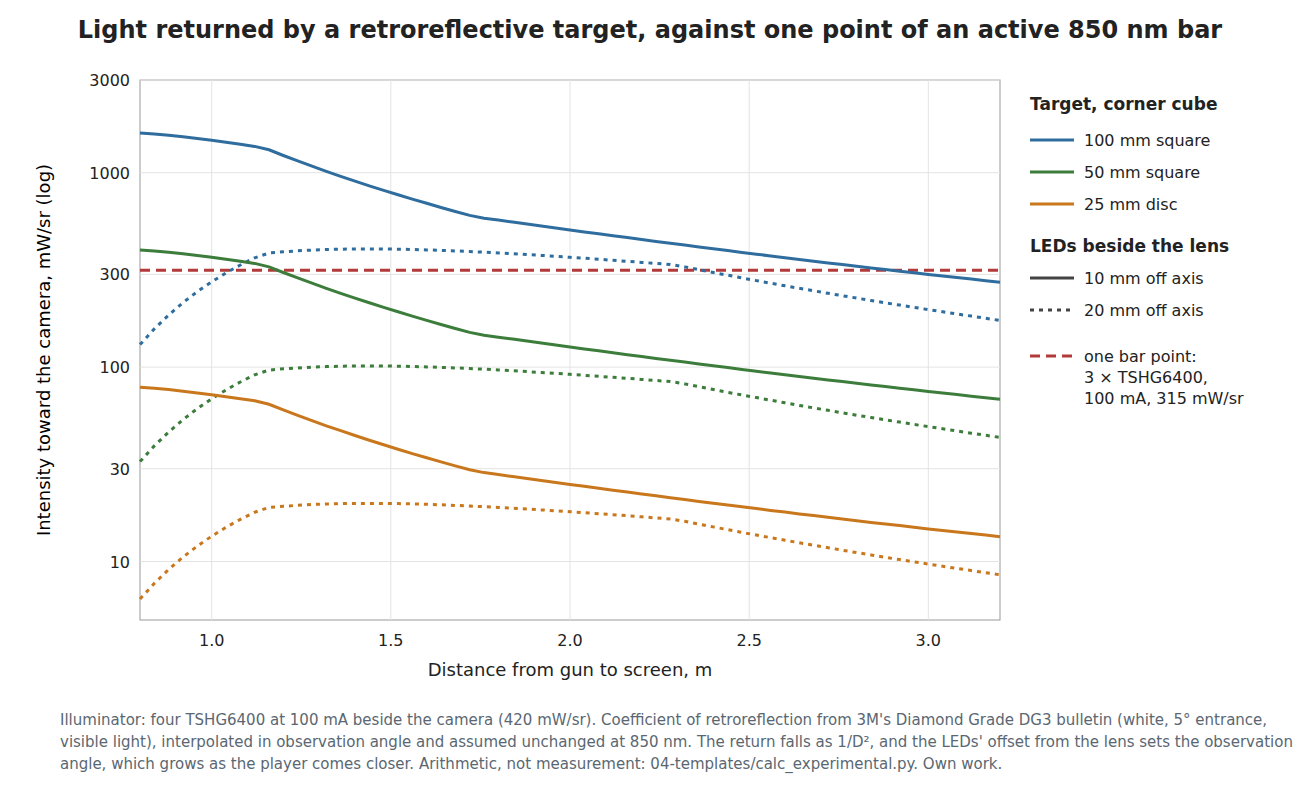
The comparison that matters is with what the gun would otherwise see: one point of the kit’s active bar, three Vishay TSHG6400 at 100 mA, about 315 mW/sr (IR Point Tracking, Volume 2). Give the gun an illuminator of four TSHG6400 at the same 100 mA, about 420 mW/sr on axis. A target of area A at distance D is lit at an irradiance of I/D² and sends back R_A × A × I/D² toward the gun. The camera then sees it at the same distance as it would see a bar point, so the comparison is fair. From 04-templates/calc_experimental.py, with the LEDs 10 mm from the lens:
Table 2 — The comparison that matters is with what the gun would otherwise see: one point of the kit's active bar, three Vishay TSHG6400 at 100 mA, about 315 mW/sr ([IR Point Tracking, Volume 2](/light-guns/sensing-and-aiming/ir-point-tracking/vol-2/)). Give the gun an illuminator of four TSHG6400 at the same 100 mA, about 420 mW/sr on axis. A target of area A at distance D is lit at an irradiance of I/D² and sends back RA × A × I/D² toward the gun. The camera then sees it at the same distance as it would see a bar point, so the comparison is fair. From 04-templates/calcexperimental.py, with the LEDs 10 mm from the lens
| Target | 1 m | 1.5 m | 2 m | 3 m |
|---|---|---|---|---|
| 25 mm disc | 0.23 × a bar point | 0.12 × | 0.08 × | 0.05 × |
| 50 mm square | 1.17 × | 0.63 × | 0.40 × | 0.24 × |
| 100 mm square | 4.7 × | 2.5 × | 1.6 × | 0.95 × |
Three conclusions follow.
- The signal falls as the fourth power of distance, not the square: the light goes out and comes back. A target that matches the bar at 1.5 m is a quarter as bright, relatively, at 3 m. Retroreflection favours close play, which is where the R3’s wide field of view is useful and its light grasp is the problem.
- Target size is the main lever. A 100 mm square at each corner of a 55-inch set is about a bar point out to 3 m with only 100 mA steady in the illuminator. A 25 mm sticker is not. A 100 mm square of sheeting at each corner of the bezel is a large, visible thing, though a black-faced or tinted variant is a question for the bench.
- Current helps linearly, and pulsing helps the same way it helps a bar (Volume 2, §2.5). Here, though, the light is in the gun, so synchronisation is free: the sensor’s own LED pin, or the firmware, times it.
There is one more geometric cost for the R3. Its 113° field of view sees all four corners from as close as 0.64 m on a 55-inch picture (IR Point Tracking, Volume 4), where the corners are about 37° off the gun’s axis. The TSHG6400’s half-intensity angle is ±27°, so at that distance the corner targets are lit at well under half intensity. A close-play illuminator wants wider-beam LEDs, or more of them fanned out. Entrance angle compounds it: a corner target seen from 30° off its face returns about half as much (the 3M figures).
3.5 The Glint
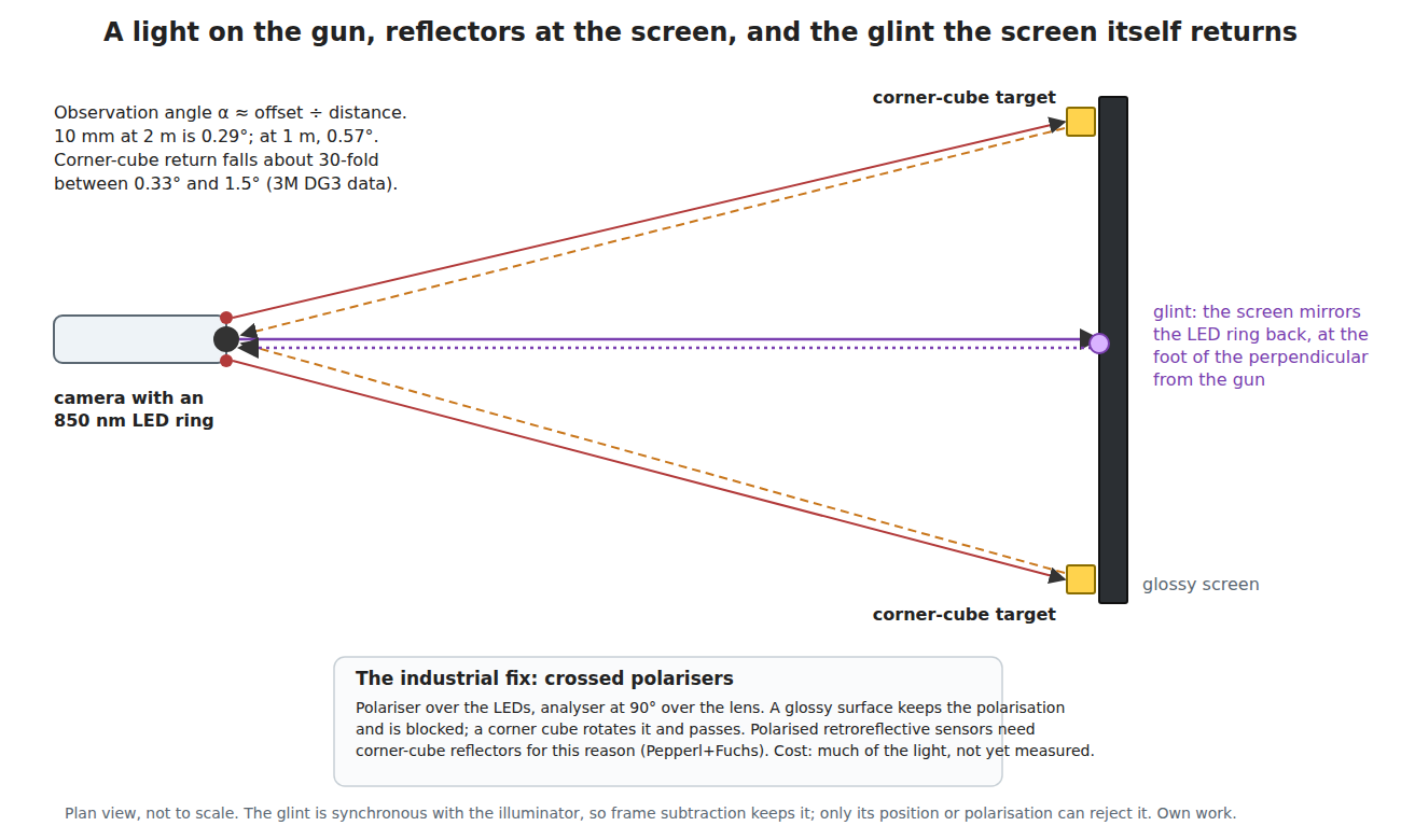
A gun carrying its own light meets a failure an active bar does not have. The television’s front is a mirror. Wherever the gun stands, there is one point on the screen where the screen’s normal passes through the gun, and at that point the screen reflects the LED ring straight back into the lens. Whenever the player stands anywhere in front of the picture, that point is inside the picture and inside the camera’s view. It is a fifth object, point-like, and it moves as the player moves.
How bright: the mirror image of the illuminator appears at twice the distance, at the screen’s reflectance times the LEDs’ intensity. Bare glass or plastic reflects about 4 % at normal incidence; anti-reflection and matt finishes much less. Against the targets, with the LEDs 10 mm off the lens:
Table 3 — How bright: the mirror image of the illuminator appears at twice the distance, at the screen's reflectance times the LEDs' intensity. Bare glass or plastic reflects about 4 % at normal incidence; anti-reflection and matt finishes much less. Against the targets, with the LEDs 10 mm off the lens
| Screen reflectance | Target | Glint ÷ target at 1 m | at 2 m | at 3 m |
|---|---|---|---|---|
| 4 % | 25 mm disc | 0.06 | 0.17 | 0.29 |
| 4 % | 50 mm square | 0.01 | 0.03 | 0.06 |
| 1 % | 25 mm disc | 0.01 | 0.04 | 0.07 |
With small targets on a glossy set, the glint is a fifth to a third as bright as a real target: easily above the sensor’s threshold. Larger targets push it down in proportion. Three properties of the glint decide the remedies:
- Frame subtraction keeps it. It is lit exactly when the targets are.
- Its position is predictable. It sits at the foot of the perpendicular from the gun to the screen, which the homography already contains: the firmware knows where the gun is relative to the screen (Aiming Maths and Calibration, Volume 5) and could mask that point. It is also always inside the quadrilateral of the four targets, where no target can be.
- Its polarisation is preserved. A specular reflection keeps the polarisation of the light that struck it; a corner cube, by its three internal reflections, changes it. Industrial polarised retroreflective sensors rely on this. Pepperl+Fuchs: “A corner-cube style reflector must be used for retroreflective sensors with polarization filters”, and with them “the sensor does not falsely detect glossy/shiny targets as reflectors”. A linear polariser over the LEDs and a crossed one over the lens would do the same in a gun. The price is light: a polariser passes well under half of unpolarised light, and the analyser passes only part of the corner cube’s return. How much is a bench measurement.
So the glint is a real problem with three plausible answers, none tested.
3.6 Power in the Gun, and Two Players
Power. Four LEDs at 100 mA steady is 400 mA from the gun’s supply, most of a USB 2.0 port’s 500 mA before the solenoid (Power Supplies). The camera only looks for 6.3 % of each frame, so the illuminator should be pulsed in step with the exposure, which in this arrangement is free (3.4). At a 600 µs window and 4 times the current, the average is about 200 mA for four LEDs; at the steady current’s brightness it is 50 mA. Retroreflection without pulsing is a poor design; with it, it is reasonable.
Two players. A retroreflector returns light toward its source within a narrow cone. Two players a metre apart at 2 m are about 28° apart as seen from the screen, far outside the cone where the sheeting returns anything, so each gun sees only its own light coming back from the targets. Two guns lighting the same stickers do not interfere, which an unmodulated active bar cannot say of a second gun system (Volume 2, §2.4). Players standing shoulder to shoulder still separate by several degrees.
Safety. An LED ring pulsed at several hundred milliamps is aimed, by design, at the screen and therefore across the room at whoever is in it. Infrared LEDs are assessed for photobiological safety under IEC 62471; a kit design would check its illuminator against that standard. It is not assessed here.
3.7 The Bench Tests
Test 1: the link budget at 850 nm. Cut 25 mm, 50 mm and 100 mm squares of a white prismatic sheeting and fix them at the four corners of a 55-inch-sized board. Fit a ring of four TSHG6400 round an R3 on its carrier, at 5 mm and then 20 mm from the lens axis (a printed holder makes the offset repeatable). With the gun clamped, record each target’s reported average and peak brightness at 1, 1.5, 2 and 3 m, then replace the targets with one point of the kit bar at the same positions. The ratio checks the table in 3.4 and, through it, whether the visible-light R_A holds at 850 nm.
Test 2: the glint. At the household television, with 50 mm targets on the bezel, stand at 1, 2 and 3 m on the centre line and 30° off it. Record the object list: count, positions, brightness. Then add linear polariser film over the LEDs and a crossed piece over the lens and repeat, noting how much the targets dimmed and whether the glint disappeared.
Test 3: pulsing from the sensor. If Volume 2’s Test 1 shows the sensor’s LED pin pulses in step with the exposure, drive the ring from it (through a MOSFET if it is not strong enough) and enable frame subtraction. Check that a lamp in view disappears from the object list and the targets do not.
3.8 Why Try This, and Why Not the Others
What it buys the build. A kit with no powered bar: four stickers, no cable or supply at the television, no LED matching. Built-in synchronisation, so pulsing and the sensor’s frame subtraction can work as PixArt designed them. Two guns that do not see each other’s light.
What it costs. An LED ring in the gun’s muzzle and its driver, a few dollars; a sheet of prismatic material; the gun’s power budget, manageable only if pulsed; and, if the glint needs them, polariser films.
The risk. The return may be lower at 850 nm than the visible figures; targets large enough to match the bar may be unacceptable on a living-room television; the glint may need polarisers that cost too much light. Failure still leaves a measured link budget and the LED-pin behaviour.
Why try this, and why not the others. It is the one idea that removes hardware from the kit rather than adding it, and the bench test is cheap. It ranks just behind the synchronised bar (Volume 2) because it returns less light than an active bar, not more, so it does nothing for the R3’s light-grasp problem except at close range. Coded frames (Volume 4) also remove the bar, but give up the camera and its accuracy; border tracking removes the bar and adds a host driver (Border Tracking, Volume 8).
3.9 What Could Not Be Verified
- R_A at 850 nm for any sheeting; all ratios use visible-light figures.
- Lee’s LED count, power and working range.
- The screen reflectance of any particular television, and the light lost to crossed polarisers with a real corner-cube sheet.
- The illuminator’s photobiological safety class.
Sources
- J. C. Lee, “Tracking Your Fingers with the Wiimote”, project page, Carnegie Mellon University, http://www.cs.cmu.edu/~johnny/projects/wii/ (2007–2008), read from the Internet Archive’s 2008 capture on 2026-10-19.
- PixArt Imaging, PAJ7025R2 General Product Datasheet, version 1.1, 29 January 2016, §1.1 and §3.3 (see Volume 2, source 1).
- 3M, Diamond Grade DG³ Reflective Sheeting Series 4090, Product Bulletin, October 2020, Tables A and B (white, CIE 54.2, illuminant A), https://multimedia.3m.com/mws/media/1469270O/ (read 2026-10-19).
- Pepperl+Fuchs, “Frequently Asked Questions about Retroreflective Sensors and Reflectors”, 14 March 2024, https://blog.pepperl-fuchs.com/en/?p=13416 (read 2026-10-19).
- Vishay, TSHG6400 datasheet Rev. 1.5 (as used in IR Point Tracking, Volume 2 and Reference Electronics, Volume 6): 105 mW/sr typical at 100 mA, ±27°.
- Arithmetic:
04-templates/calc_experimental.py, output in02-inputs/calc-output.txt.
Comments (0)