Experimental Sensing · Volume 2
Frame Subtraction and the Synchronised Bar — Using the Features PixArt Built In
The PAJ7025 has a frame-subtraction register and LED pins rated for 130 to 170 mA that no light-gun firmware touches. What the datasheets actually say, what pulsing and subtraction could buy an R3 gun, three ways to tell a bar when the camera is looking, and the bench tests that settle it
2.1 What a Steady Bar Cannot Do
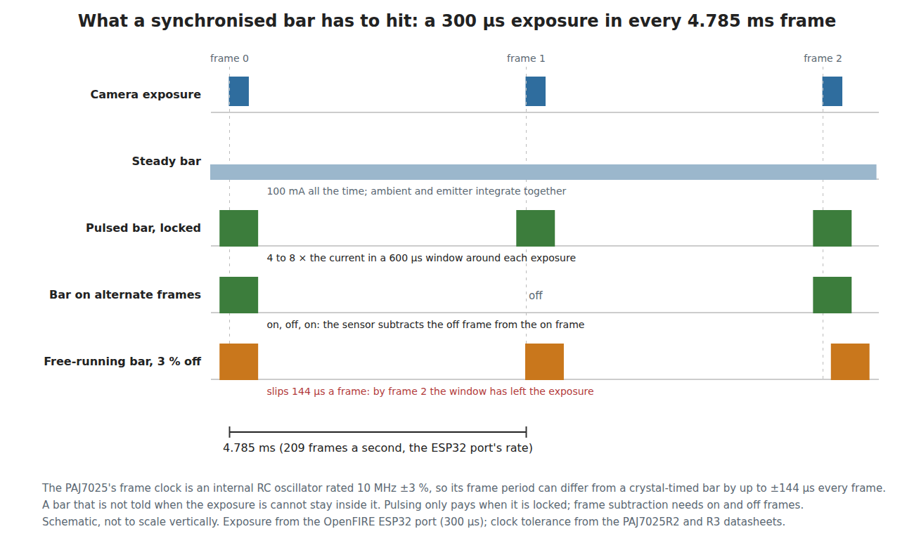
Every published DIY bar runs its LEDs on steady current, and Reference Electronics, Volume 6 gives the reason: pulsing only helps if the pulses land in the camera’s exposure, and OpenFIRE has no way to tell the bar when that is. The result is a bar that competes with the room on equal terms. A lamp, a sunlit wall or the bar’s own reflection in a glass cabinet integrates over exactly the same 300 µs as the emitter does, and the only defences are the sensor’s thresholds and the firmware’s choice of which four blobs to believe (IR Point Tracking, Volume 5).
The kit camera makes that contest harder. IR Point Tracking showed, from the two datasheets, that the PAJ7025R3’s entrance pupil collects about a thirty-ninth of the light the R2’s collects from the same emitter, and that the R3’s ratio of emitter to background is about a fifteenth of the R2’s (Volume 2, §2.8). The R3 was chosen for its field of view, which no other buyable part offers; the price is a dimmer signal. Anything that raises the emitter’s share of the exposure without raising the room’s buys some of that back.
Two techniques do exactly that, and the PixArt part was built with both in mind: pulse the emitter only while the camera looks, and subtract a frame taken with the emitter off.
2.2 What the Datasheets Say
Three PixArt documents were read for this volume. Two are “PixArt Confidential” partial copies reproduced in a public KiCad library on GitHub; the third is a 12-page General Product Datasheet that PixArt published on its own server in 2016 and that the Internet Archive holds.
PAJ7025R2 General Product Datasheet, version 1.1, 29 January 2016. This is the most useful of the three because it contains the register table, which the confidential partial copies do not. It states:
- In register bank 0, address
0x28, a register namedCmd_FrameSubtraction_On, default 0, described as “1->Frame Subtraction Enable”. - Pins 18 and 19,
G14/LED_FRTandG13/LED_SIDE, each “Reserved pin for IR LED Control”, with pin 20,VSSD_LED, a separate ground: “This pin must be connected to ground.” - In the electrical notes: “All the GPIO maximum output current is 4mA”, and then “IR-TX LED driving pin is 130~170mA.” The LED pins are not logic outputs. They are drivers sized to run an infrared LED directly, returning through their own ground pin.
- Frame period in register bank 2, addresses
0x07to0x09, “unit = 100ns”, default 49,780 (4.978 ms, about 201 frames a second), and exposure in0x0Fand0x10, “unit = 200ns”, default 8,192 (1.638 ms). - “System clock: 10MHz±3% @25°C (internal clock)”, and “Shutter Type: Global Shutter”.
- And in its introduction: “In the application environment the moving object(s) could have active IR light source or passive IR reflector.”
PAJ7025R2 Product Datasheet, version 1.3, 21 November 2019 (confidential, partial). As IR Point Tracking read it, its key features list “Frame subtraction function”, its block diagram has an “External LED Control” block driving G13/LED_SIDE, its pin table describes that pin as “G13 or LED Sync … Can be programmed as LED output pin via register”, a second pin as a VSYNC output and a third as a trigger input for “Frame On Demand” mode, and its contents list a figure titled “LED_On control signal for frame subtraction” whose page is missing from the copy (IR Point Tracking, Volume 1, §1.9).
PAJ7025R3 Product Datasheet, version 1.0, 16 December 2016 (confidential, 11 of 39 pages). The pages read here show the kit camera carries the same features:
- Pin 10,
G13/LED_SIDE, and pin 11,G14/LED_FRT, each “Reserved pin for IR LED Control”, on the 14-contact module’s edge connector. - In PixArt’s application circuit (Figure 5), both LED pins go to test points TP5 and TP6, and
G8to TP4. They are brought out, not buried. - A section 6.4.6, “Frame Subtraction”, listed in the contents on page 26, which is not in the copy.
- “Shutter Type: Global Shutter” and the same “10MHz±3%” internal clock.
So the existence of the feature on both modules is documented by PixArt, and enabling it is one register write. What the sensor does with its LED pins once it is enabled, the polarity and timing of the LED drive, whether it alternates on and off frames, and whether the subtraction happens on pixels before the threshold or on objects after it, are in pages that were not available. Nobody’s published firmware writes the register: the OpenFIRE ESP32 port’s PixArt_PAJ7025 driver, read on 19 October 2026, configures banks 0, 1 and 0x0C and never touches bank 0 address 0x28, so the default, off, applies in every light gun found.
2.3 How Frame Subtraction Works, and What It Costs
The principle is old and simple. Take one frame with the emitter lit and one with it dark, subtract the second from the first, and threshold the difference. Anything equally bright in both frames, which is every steady source in the room, cancels; the emitter survives. Lee and his co-authors used exactly this in their 2004 projector-calibration work with photodiodes, noting that “projecting each calibration pattern followed by its inverse and then differencing the two readings … cancels out the effects of ambient lighting, but requires projecting twice as many patterns.”
That last clause names the first cost. Four costs matter for a gun:
- Rate. If every on frame needs its own off frame, the useful report rate halves: 209 frames a second becomes about 104 reports. A sensor can avoid that by subtracting the most recent off frame from each on frame on a rolling basis, but whether the PAJ7025 does so is not documented.
- Latency. At least one extra frame period, 4.8 ms, in the worst case.
- Noise. Subtraction cancels the background’s mean, not its photon noise; the noise of both frames adds. Against a dim emitter in a bright room this is the limit, but it is a far better limit than a background that sits above the threshold.
- Motion. The gun moves between the two frames. A swing of 180° a second moves the image 0.86° in one 4.8 ms frame, about three quarters of one R3 pixel. A steady lamp therefore does not cancel perfectly: it leaves a thin positive and negative fringe at its edges, at most a pixel wide. That residue is small and blob-shaped only for a small lamp, and the sensor’s area and brightness thresholds should reject it, but it is a bench question.
What subtraction cannot do is remove anything that blinks in step with the emitter. The emitter’s own reflection in a window or a glossy cabinet is lit in the on frame and dark in the off frame, exactly like the emitter, and survives. So does the glint of a gun-mounted light in a glossy screen (Volume 3). Subtraction removes the room; it does not remove the bar’s own images.
2.4 The Arcade Precedent
Arcade makers met the same problem two decades ago and solved a version of it. Sega’s House of the Dead III manual tells an operator to “remove the jumper harness (SPY-60010UK) from every other machine in the line” because “a removable wire harness controls the operating frequency of the gun sense system”, and Namco’s Time Crisis 4 manual gives the same instruction for its “Frequency Change connector” (Arcade Light Guns, Volume 4). “Operating frequency” implies modulated LEDs and a receiver tuned to them, so that a neighbouring cabinet’s LEDs, at the other frequency, are rejected. Neither manual gives the frequency, and how the guns’ cameras demodulate it is not published.
The home equivalent is a bar whose light carries a pattern the gun can recognise: on in some frames and off in others, or pulsed only in the exposure. It rejects a second gun system in the room in the same way the jumper did, and it rejects the steady room light that the jumper never had to.
2.5 The Arithmetic of Pulsing
The OpenFIRE ESP32 port runs the PAJ7025 at a requested 209 frames a second, a period of 4.785 ms, with a 300 µs exposure (IR Point Tracking, Volume 1, §1.7). The camera is collecting light for 6.3 % of the time. A steady bar wastes the other 93.7 %.
If the bar is lit only in a window round each exposure, its average power falls by the window’s duty, and the current during the window can rise by the same factor before the LED’s average dissipation is back where it was. The ideal factors, from 04-templates/calc_experimental.py:
Table 1 — If the bar is lit only in a window round each exposure, its average power falls by the window's duty, and the current during the window can rise by the same factor before the LED's average dissipation is back where it was. The ideal factors, from 04-templates/calcexperimental.py
| Window round each exposure | Duty | Peak ÷ steady current at the same average power |
|---|---|---|
| 400 µs | 8.4 % | 12 × |
| 600 µs | 12.5 % | 8 × |
| 1,000 µs | 20.9 % | 4.8 × |
The LED’s pulse rating, not its average power, is the real ceiling. The ams OSRAM SFH 4547 (the 940 nm stopgap bar’s LED) takes 1 A for up to 400 µs at a duty of 0.5 % or less, against 100 mA continuous, and at 209 frames a second a 300 µs pulse is a 6 % duty, twelve times that limit (IR Point Tracking, Volume 2, §2.9). The kit bar’s 850 nm Vishay TSHG6400 has its own pulse ratings, which must be read from its datasheet before choosing a current; they are not used here. A factor of 4 over the steady 100 mA, inside a 600 µs window, is a reasonable first target to check against them.
What a current factor buys: the emitter’s signal in the exposure rises by the factor; the room’s does not. At equal camera signal, range scales as the square root, so a factor of 2 is 1.41 times the range, 4 is 2 times and 8 is 2.83 times. The R3’s light-grasp deficit against the R2 is a factor of about 39, so pulsing alone will not make an R3 reach as far as an R2. It can roughly double the R3’s range on the same bar, or let the same range be held in a brighter room. Frame subtraction then adds rejection of everything steady on top.
2.6 Three Ways to Synchronise a Bar
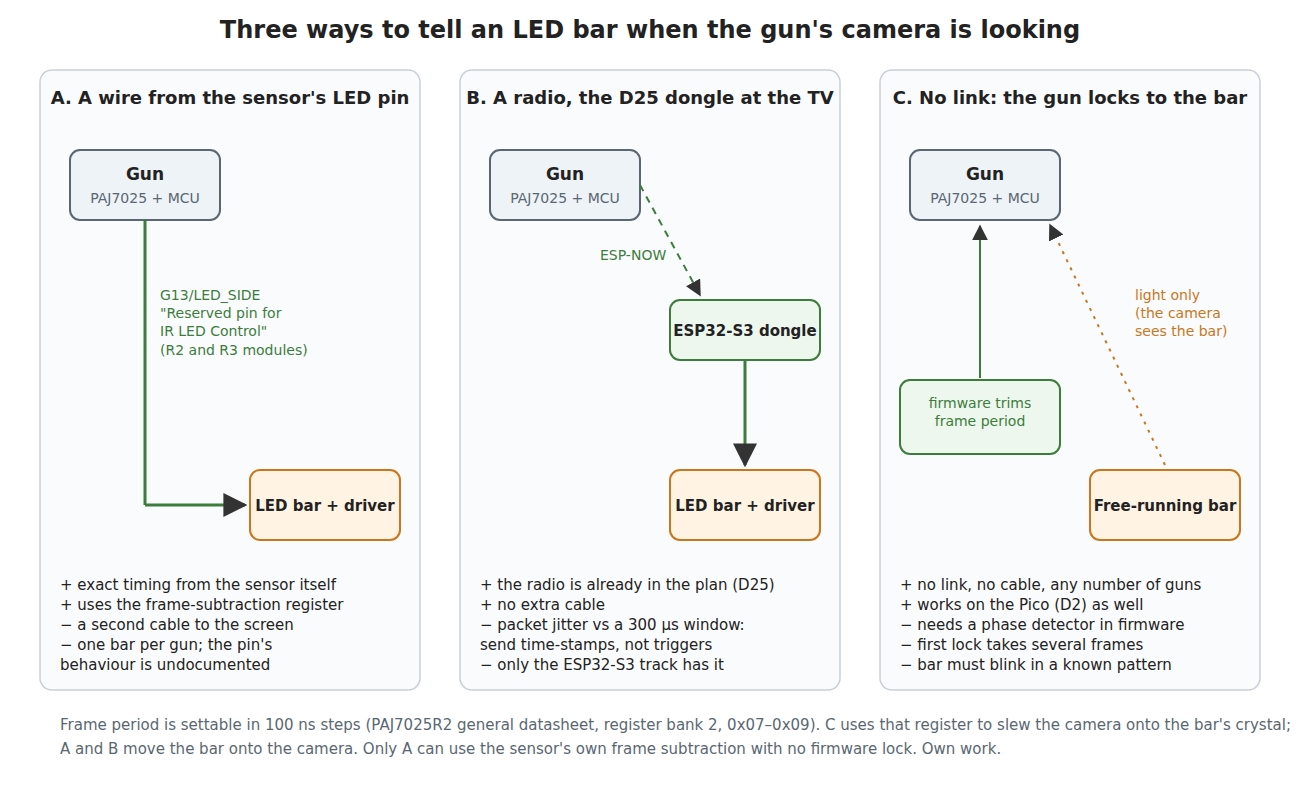
A pulsed bar needs to know when the exposure is, to within a fraction of 300 µs. The PAJ7025’s clock makes this harder than it looks: both datasheets rate the internal oscillator at 10 MHz ±3 %, so the frame period of one sensor can differ from a crystal-timed bar’s by up to ±144 µs every frame. A crystal at ±50 ppm drifts 0.24 µs a frame by comparison. A bar that simply runs at “209 Hz” will walk out of a 600 µs window within one or two frames, as the bottom row of the timing figure shows. Something must close the loop. Three arrangements can:
A. A wire from the sensor’s LED pin. The sensor’s own G13/LED_SIDE or G14/LED_FRT drives the bar’s driver input (a logic-level MOSFET or the bar’s existing constant-current stage), down a second conductor in the gun’s cable. Timing is exact by construction, and if the sensor’s frame-subtraction mode alternates its LED pin, the bar follows. Its costs: a conductor from gun to screen, which a wired gun can carry alongside USB and a wireless gun cannot; one bar per gun, unless two guns’ pins are combined; and the pin’s behaviour is undocumented, so the first job is to see it on the oscilloscope (2.9).
B. A radio. Decisions D25 and D30 already put an ESP32-S3 dongle at the host for the wireless trial (Open-Source Firmware, Volume 6). A dongle at the television could drive the bar. But ESP-NOW is a packet radio, and its delivery time varies by far more than a 300 µs window allows, so the gun cannot send “flash now”. It must send its frame timing as time-stamps, and the dongle must keep its own schedule disciplined to them, which is the same loop as C with a radio added. The radio’s jitter was not found published and would have to be measured.
C. No link: the gun locks to the bar. The bar runs from its own crystal, lit in a fixed pattern, for example on in a 600 µs window in alternate frames of a nominal 209 Hz. The gun’s firmware treats the reported brightness of the four points as a phase detector: if the exposure sits at the edge of the window the points are dim or missing, if it sits in the middle they are bright. It trims the PAJ7025’s frame-period register, which moves in 100 ns steps, a frequency resolution of about 21 ppm at this period, until the exposures sit in the windows, and keeps trimming as the sensor’s RC clock drifts with temperature. One step of residual error walks 150 µs in about seven seconds, so a correction every few frames is ample. A cold start has to search: at worst a few dozen frames, a fraction of a second, to find the window.
C has three properties the others lack. It needs no cable and no radio. It works on the Pico (D2) as well as the ESP32-S3, because it is firmware and one SPI register. And any number of guns can lock to the same bar independently, as arcade cabinets on the same frequency never could. Its cost is a small control loop in firmware and a bar with a crystal, a timer and a MOSFET instead of plain constant current. Whether the sensor’s own frame subtraction can be used with it depends on the undocumented question of how the sensor decides which frames are “on”; if it cannot, the firmware can do the comparison itself (2.7).
2.7 Subtraction in Firmware Instead
If the sensor’s subtraction proves unusable with a free-running bar, the gun can do a coarser version from the object reports. With the bar on in alternate frames, the firmware keeps the last off-frame object list and discards from each on-frame list any object that also appears, at nearly the same place and brightness, in the off frame.
This is weaker than pixel subtraction in one important way. It cannot rescue an emitter that sits on top of a bright background, because the background still has to fall below the sensor’s threshold for the emitter to be reported as a separate object at all. But it is strong against what actually breaks guns in a living room: a lamp, a window glint or a remote control that the firmware mistakes for a fifth point (IR Point Tracking, Volume 5). Those appear in both frames and are dropped by identity rather than guessed at by position. As with the sensor’s version, the bar’s own reflections blink with it and are not rejected.
The PAJ7025’s 15-field object record, with average and peak brightness, area and bounding box (IR Point Tracking, Volume 1, §1.5), gives the matching enough to work with. The Wii-class camera’s Basic report gives only position and size, which would make the same trick far cruder on the stopgap camera.
2.8 Global Shutter Is a Requirement
Pulsing assumes every pixel exposes at the same moment. Both PAJ7025 modules are global-shutter parts. A rolling-shutter camera exposes each row at a different time: the ESP32-IR project’s OV2640 configuration reads about 296 lines at 136 frames a second, a line every 24.8 µs and 7.35 ms from top to bottom (Volume 5). A short pulse there lights only the band of rows exposing at that instant, so emitters at the top and bottom of the image would need different pulse times, and a pulse long enough to cover them all is no longer a pulse. For the general-camera route of Volume 5, synchronised bars therefore buy little unless the sensor has a global-reset or strobe mode; the Arducam HM0360’s product page lists “External frame synch”, which is a lead worth reading in its datasheet, not a conclusion.
2.9 The Bench Tests
Three experiments answer the open questions, in order. All use a PAJ7025R3 (and an R2 for comparison) from the CODICO sample kits on a carrier with the module’s test points brought out, driven over SPI from the Pico.
Test 1: what the LED pins do. With the sensor running at 209 frames a second, probe G13/LED_SIDE and G14/LED_FRT with the ADP3450’s oscilloscope through 10 kΩ to ground, never driving them, first with register 0x28 at 0, then at 1. Capture against the SPI chip-select as a frame marker on a logic channel. The question: does the pin pulse, at what width, polarity and phase relative to the frame, and on every frame or alternate ones? Then, only if the waveform is a clean output, load it with a 10 Ω sense resistor and one TSHG6400 to see whether it sinks current as “IR-TX LED driving pin is 130~170mA” says.
Test 2: a free-running pulsed bar and a firmware lock. Drive a bar point (three TSHG6400 on a logic-level MOSFET with a current-set resistor) from the ADP3450’s pattern generator: 600 µs pulses at a nominal 209 Hz, on alternate frames. Log the R3’s reported average brightness for that point as the pattern generator’s phase is stepped across the frame in 50 µs steps, with the gun clamped at 2 m. The curve is the phase detector of architecture C: a plateau as wide as the window minus the exposure, falling to nothing outside it. Then run the trimming loop in firmware and log lock time from a cold start and lock held over ten minutes as the sensor warms.
Test 3: what it buys in a real room. At the household television, with a lamp and a window in view, record the R3’s reports at 2 m and 3 m in four conditions: steady 100 mA bar; locked pulsed bar at 4 times the current; pulsed bar with the sensor’s frame subtraction on (if Test 1 shows it can follow an external bar); and pulsed bar with firmware subtraction. Score each by the margin between the weakest emitter’s brightness and the threshold, the count of spurious objects, and the farthest distance at which all four points are held.
2.10 Why Try This, and Why Not the Others
What it buys the build. Several times the bar’s effective brightness for the same average power, which roughly doubles the R3’s range on a given bar or holds the same range in a brighter room; rejection of steady room light; and, through the bar’s pattern, immunity to a second infrared gun system in the room. All of it on the chosen camera (D18) and the chosen board (D2), with no new parts in the gun.
What it costs. For architecture C, a bar with a microcontroller or timer, a crystal and a MOSFET, a few dollars over the current constant-current bar, and a control loop in the private firmware fork. For A, a conductor in the cable. Test 1 costs nothing but bench time once the sample kit is in hand.
The risk. The sensor’s frame subtraction may assume its own LED pin timing and not follow an external bar; then the gain is pulsing plus firmware subtraction, which is still most of the benefit. The LED pins are “reserved”, so PixArt may change or not support them; a design that depends only on the frame-period register (C) does not need them at all.
Why this first. It is the only idea in this dive that attacks both weaknesses of the chosen design, the R3’s small pupil and the room light, without changing the camera, the board or the firmware’s structure. Retroreflectors (Volume 3) remove the bar’s power cable but return less light, not more. A second camera (Volume 6) recovers range by adding a part. The general-camera and border ideas (Volume 5) change the sensor entirely.
2.11 What Could Not Be Verified
- The behaviour of
G13/G14and of frame subtraction once enabled: timing, polarity, alternation, whether subtraction is on pixels or objects, and whether it can follow an external light source. The pages describing them were not in either partial copy. - Whether the PAJ7025 rolls its subtraction (every frame) or pairs frames (half the rate).
- The TSHG6400’s pulse ratings, which set the usable current factor.
- ESP-NOW delivery jitter on the D25 hardware.
- The arcade cabinets’ modulation frequency.
Sources
- PixArt Imaging, PAJ7025R2 General Product Datasheet, version 1.1, 29 January 2016, document 51000AEN, 12 pages: §1.1, §1.3 features, Table 1 pin description, §3.3 notes, Tables 2 to 4 register banks 0, 1 and 2. Originally at
pixart.com.tw/upload/PAJ7025R2_GDS_V1.1_29012016_20160622212619.pdf(linked from the University of Regensburg HCI group’s “Cool Hardware” page); that server timed out on 19 October 2026 and the file was read from the Internet Archive’s 2017 capture. - PixArt Imaging, PAJ7025R3 Product Datasheet, version 1.0, 16 December 2016, “PixArt Confidential”; an 11-page partial copy in alextrical/PAJ7025-KiCad-Library on GitHub (
datasheet/paj7025r3.pdf), pages rendered and read 2026-10-19: contents, §1.2 block diagram, §1.3 features, Table 1 pin description, Figure 5 application circuit. - PixArt Imaging, PAJ7025R2 Product Datasheet, version 1.3, 21 November 2019, as read for IR Point Tracking, Volume 1.
- Alessandro Satanassi, OpenFIRE-Firmware-ESP32,
PixArt_PAJ7025.cpp(LGPL), read 2026-10-19: register writes inbegin()andloadInitialSettings(). - J. C. Lee, P. H. Dietz, D. Maynes-Aminzade, R. Raskar, S. E. Hudson, “Automatic Projector Calibration with Embedded Light Sensors”, UIST 2004, pp. 123–126; MERL TR2004-036, https://merl.com/publications/docs/TR2004-036.pdf, read 2026-10-19.
- Sega, The House of the Dead III service manual, and Namco, Time Crisis 4 manual, as quoted in Arcade Light Guns, Volume 4.
- Arithmetic:
04-templates/calc_experimental.py, output in02-inputs/calc-output.txt.
Comments (0)