Aiming Maths and Calibration · Volume 1
From Dots to a Screen Position — the Camera Model, the Boresight and the Lens
What the firmware is actually computing when four infrared points become a cursor: the pinhole model in each camera's own units, the one number it must learn by calibration, and the PAJ7025R3's wide lens, with its correction re-derived and its uncorrected error put in millimetres
1.1 The Problem in One Paragraph
A camera-in-the-gun light gun receives, every camera frame, the image positions of up to four infrared emitters fixed around the screen. From those eight numbers it must produce one pair: the place on the picture where a line along the barrel meets the screen. Everything between the sensor’s report and the USB mouse report is mathematics, and that mathematics is this dive. It has seven parts: the camera model and its lens (this volume); naming the points and the simple models that came before the homography (Volume 2); the homography itself, its derivation, conditioning and cost on an RP2040 (Volume 3); what each calibration shot actually solves for (Volume 4); the offset between the camera and the bore (Volume 5); smoothing (Volume 6); and the accuracy and latency budgets, with off-screen detection (Volume 7).
Every number in the dive comes from a pure-Python simulation, 04-templates/aim_maths.py, which re-implements the firmware arithmetic line for line from the source and runs it against an ideal camera whose pose is known exactly. Its output is in 02-inputs/calc-output.txt. Nothing here has yet been measured on the bench; where a measurement will replace a simulated figure, the place is marked.
1.2 What This Dive Owns, and What It Links To
The boundary with the sibling dives matters, because several of them already describe the same code from a different side.
- IR Point Tracking owns the sensor and the emitters: what the camera reports (its Volume 1), how many points and where to put them, including a simulation of the model error of two-, three- and four-point methods (Volume 3), and the playing envelope against field of view and distance (Volume 4). Its Volume 3 §3.8 hands three things to this dive: the centroid noise, the baseline and the distance. This dive takes them from there.
- Open-Source Firmware owns OpenFIRE as software: the source tree, the camera driver, the pipeline in outline (Volume 2) and the calibration and smoothing settings as a user meets them in the App (Volume 5). This dive does not repeat those descriptions. It takes the same lines of code and asks what they compute, what they assume and how large their errors are.
- Reference Electronics, Volume 3 owns the choice of camera and its wiring; the datasheet figures used here for the PixArt cameras are the ones it established.
- Border Tracking uses a homography too, from a drawn border rather than emitters. The algebra of Volume 3 applies to it unchanged.
Four firmware sources were read for this dive, all on 19 October 2026: OpenFIRE v6.2 (TeamOpenFIRE/OpenFIRE-Firmware, branch OpenFIRE-dev, commit 8b651a25, identical to the v6.2 release); Samco (samuelballantyne/IR-Light-Gun, 929490f3); Prow Enhanced (Prow7/ir-light-gun, aeab7d1c); and the ESP32 port (alessandro-satanassi/OpenFIRE-Firmware-ESP32, f6458fc9, pushed the same day — a moving target, so line numbers here refer to that commit). GUN4IR is closed source; nothing can be said about its mathematics beyond its user guide’s description of “a five-step calibration of camera offset and LED placement” (Open-Source Firmware, Volume 1).
1.3 The Pinhole Model in the Camera’s Own Units
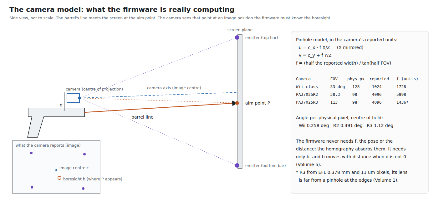
The firmware never sees millimetres on a sensor. It sees integers in whatever range the camera reports, and the model has to be written in those units. For a pinhole camera looking along its own Z axis, a point at (X, Y, Z) in the camera’s frame lands at
u = c_x − f · X / Z        (X reversed: see below)
v = c_y + f · Y / Z
where (c_x, c_y) is the centre of the reported range and f is the focal length expressed in reported units, f = (half the reported width) / tan(half the horizontal field of view). The minus sign on u is real: OpenFIRE’s square-layout code reverses X before doing anything else (OpenFIRE_Square.cpp line 99, map(positionXX[i], 0, MouseMaxX, MouseMaxX, 0)), because the camera sees the scene mirrored relative to the screen.
The three cameras in this category, in their own units:
Table 1 — The three cameras in this category, in their own units
| Camera | Horizontal field | Physical pixels across | Reported range | f, reported units | Angle per physical pixel, centre |
|---|---|---|---|---|---|
| Wii-class (DFRobot SEN0158, harvested Wii sensor) | 33° | 128 | 0–1023 | 1,728 | 0.258° |
| PixArt PAJ7025R2 | 38.3° | 98 | 0–4095 | 5,898 | 0.391° |
| PixArt PAJ7025R3 | 113° (datasheet) | 98 | 0–4095 | 1,436 | 1.12° |
Fields of view are those IR Point Tracking, Volume 4 and Reference Electronics, Volume 3 took from WiiBrew and the PixArt datasheets; the reported ranges are the ESP32 port’s camera profiles (OpenFIRECameraProfile.h lines 280–338). The R3’s f is not taken from its field of view but from its effective focal length, 0.378 mm, over 11 µm pixels, because its lens is not a pinhole at the edges of the field (1.7). OpenFIRE v6.2 shifts the Wii-class camera’s coordinates left by two bits before any arithmetic (CamToMouseShift = 2, OpenFIREConst.h), so inside the firmware that camera’s range is 0–4095 as well, and f is four times the table’s figure.
Two cautions about the reported range. It is not the resolution: the Wii-class sensor has 128 physical pixels across and reports 1,024 positions by computing a blob centroid to an eighth of a pixel (IR Point Tracking, Volume 1), and the PixArt sensors report 4,096 from 98. And the Wii-class camera’s pixels may not be square in reported units: 33° by 23° over 1,024 by 768 gives 0.0322° per unit across and 0.0300° per unit down. The simulation uses the horizontal figure for both axes; the difference is one of the things the homography absorbs without being told (1.4).
1.4 What the Firmware Never Needs to Know
A striking thing about all four firmware sources is what is absent from them. There is no focal length, no field of view, no camera height, no screen size in millimetres and no player distance anywhere in the OpenFIRE aiming code. The reason is the central fact of the method.
The screen is a plane, and a pinhole camera’s view of a plane is related to the plane itself by a homography: a 3 × 3 matrix, defined up to scale, with eight free numbers. The camera’s focal length, its non-square pixels, the player’s distance, height, sideways offset and the gun’s yaw, pitch and roll all fold into those eight numbers. Four points at known places on the plane, seen in the image, determine them exactly, every frame (IR Point Tracking, Volume 3 counts the degrees of freedom; Volume 3 of this dive derives the matrix). So the firmware can rebuild the whole camera-to-screen relationship sixty to two hundred times a second without ever knowing what any of its physical parameters are.
What the homography does not contain is the gun. It describes how the screen looks from the camera. It says nothing about where the barrel points. That is the job of the boresight.
1.5 The Boresight
Push an image point through the homography and the result is the place on the screen that the camera sees at that image point. To get the aim point, the firmware must push through the image point at which the aim point appears. Call it the boresight, b.
If the camera sat exactly on the barrel’s axis and looked exactly along it, b would be the image centre, (c_x, c_y), for every target at every distance. Real guns are not built that way:
- The camera’s axis is tilted from the bore by a small angle, through the tolerance of a printed mount or a camera board soldered slightly askew. A tilt moves b to a fixed point away from the centre, the same at every distance. One calibration shot finds it and it stays found.
- The camera sits beside the bore, a distance d above or below or to one side. Then b depends on distance: a point on the bore line at distance D is seen at an angle d/D off the camera’s axis. One calibration shot finds b at one distance only. Volume 5 works out the error, which is d (1 − D/D_cal) on the screen, and what can be done about it.
OpenFIRE stores b in each profile as adjX and adjY and sets it from the first trigger pull of calibration, while the player aims at the centre of the screen (Volume 4 reads that code). The figure at the top of this volume shows the geometry. Everything else in calibration is about the screen; this one shot is about the gun.
1.6 Lens Distortion: Narrow Lenses
The pinhole model assumes that a straight line in the world is a straight line in the image. A real lens bends the image radially: barrel distortion pulls points near the edge of the field inward, pincushion distortion pushes them outward. A homography cannot represent either, so whatever distortion is left in the points becomes an aim error that changes across the screen and with the player’s position.
For the two narrow cameras it is small. The PAJ7025R2’s datasheet gives a distortion of less than 2.8 % over a 38.3° field (the R2 datasheet’s optical table, as read in IR Point Tracking, Volume 1). No distortion figure was found for the Wii-class camera. The ESP32 port nonetheless carries a small correction for it, K1 = 0.006 in its profile (OpenFIRECameraProfile.h line 290), which in the port’s normalised units moves a point in the extreme corner of the field outward by 1.2 %; the source gives no derivation for the figure, and it is treated here as a tuning value, not a measurement. The R2’s coefficients are zero, and the port’s own lens note explains why it chose not to fit them: applied mechanically to the R2’s nominal focal length and field of view, its fitting method implies about +4.6 % distortion, against the datasheet’s “<2.8 %”, which it reads as a sign that nominal figures with tolerances “must not be treated as an exact calibration” (OpenFIRE-Lens-Correction-EN-IT.md, section 10).
1.7 Lens Distortion: the PAJ7025R3
The R3 is the camera the category’s decision log proposes for a kit (row P-RE16), chosen for its wide field, which lets a player stand close to a large television (Reference Electronics, Volume 3). The datasheet, as read there, gives an effective focal length of 0.378 mm ±5 %, a field of view of 113° ±5 % horizontally and vertically and 142° ±5 % diagonally, and a distortion of −30 %. Thirty per cent is not a small correction, and the R3 is the only camera in the category for which the lens is a first-order part of the aiming maths.
1.7.1 The ESP32 port’s model
The port is the only light-gun firmware found that corrects for lens distortion. It applies the correction in OpenFIRE_Perspective_Advanced.cpp (lines 145–168) to each of the four points and to the boresight before the homography:
nx = (x − cx) / cx,   ny = (y − cy) / cy          (normalised to ±1 at the sides)
C  = 1 + K1·(nx² + ny²) + K2·(nx² + ny²)²
C  = clamp(C, lensCorrectionMin, lensCorrectionMax)
x' = cx + (x − cx)·C,   y' = cy + (y − cy)·C
C is an observed-to-corrected factor: it moves the point the lens actually produced outward to where a pinhole lens would have put it. The port’s design note, OpenFIRE-Lens-Correction-EN-IT.md, derives K1 and K2 for the R3 from two anchors. With f the effective focal length and a = 0.539 mm the sensor’s half-width (98 pixels of 11 µm):
C_s = f · tan(θ_s) / a            at the middle of a side (r = 1)
C_d = f · tan(θ_d) / (a·√2)       at a corner (r = √2)
K2  = (C_d − 2·C_s + 1) / 2
K1  = C_s − 1 − K2
The derivation is sound and the note is careful about its limits: “These are theoretical starting values, not a measured lens calibration”, and “Two coefficients can fit two nominal points exactly, but this does not establish accuracy between those points or on an individual camera”. It also checks that the corrected radius stays monotonic across the field (minimum derivative 0.952), so the correction cannot fold the image over, and it explains its choice of a 1.5 upper clamp: the nominal correction reaches 1.36 in the corners and the earlier 1.2 limit “would clip the correction before reaching the corners”.
1.7.2 Re-deriving it from the datasheet
The note’s inputs are a horizontal field of 111.3° and a diagonal of 140°. The datasheet figures recorded in Reference Electronics are 113° and 142°. Both pairs are within the datasheet’s ±5 %, and the note’s are consistent with PixArt’s marketing figure of “140°”, which Reference Electronics established is the diagonal. Running the same fit on both:
Table 2 — The note's inputs are a horizontal field of 111.3° and a diagonal of 140°. The datasheet figures recorded in [Reference Electronics](/light-guns/building-the-electronics/reference-electronics/vol-3/) are 113° and 142°. Both pairs are within the datasheet's ±5 %, and the note's are consistent with PixArt's marketing figure of "140°", which Reference Electronics established is the diagonal. Running the same fit on both
| Inputs | C_s | C_d | K1 | K2 | Implied distortion, side | Implied distortion, corner |
|---|---|---|---|---|---|---|
| Port profile, 111.3° / 140° | 1.0261 | 1.3625 | −0.1289 | 0.1551 | −2.5 % | −26.6 % |
| Datasheet, 113° / 142° | 1.0596 | 1.4402 | −0.1010 | 0.1605 | −5.6 % | −30.6 % |
Distortion here is D = 1/C − 1, the definition the port’s note uses (its section 7). The datasheet-input fit lands within 0.6 points of the datasheet’s own “−30 %”; the port’s lands 3.4 points short. The port’s note itself observes the gap (“−26.60 % … of the same order as −30 %, but it is not identical”) and attributes it to tolerances, which is fair. The difference does not make the port wrong. It shows that the two published figures most likely to be used as anchors give coefficients that differ by about a quarter in K1, which is exactly why the note asks for a measurement.
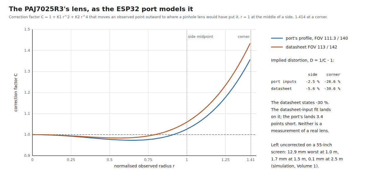
The shape is worth noticing. Both curves dip a little below 1 between the centre and r ≈ 0.8, then rise sharply. With only two coefficients and two anchors, the inner dip is a property of the polynomial, not necessarily of the lens; the note says as much (“this does not prove that the real lens follows exactly that curve”). A lens with −30 % in the corners and only −2.5 to −5.6 % at the sides is, by the numbers, nearly rectilinear along its axes and strongly compressed toward its corners, which is consistent with a 113° horizontal field fitted to a sensor whose diagonal is 1.41 times its width.
1.8 What the R3’s Lens Costs if Left Alone
How much does the correction matter? The simulation answers it by taking the datasheet-input fit as the truth (an assumption: the real lens is unmeasured), distorting the ideal image points with it, and running the full OpenFIRE pipeline with and without correction. Square layout, 55-inch picture, emitters 30 mm outside it, calibrated where the player stands, then tested at nine targets from the same place and from 30° to one side:
Table 3 — How much does the correction matter? The simulation answers it by taking the datasheet-input fit as the truth (an assumption: the real lens is unmeasured), distorting the ideal image points with it, and running the full OpenFIRE pipeline with and without correction. Square layout, 55-inch picture, emitters 30 mm outside it, calibrated where the player stands, then tested at nine targets from the same place and from 30° to one side
| Player distance | Uncorrected, worst | Uncorrected, after moving 30° aside | Port’s coefficients, worst | Datasheet-input coefficients |
|---|---|---|---|---|
| 1.0 m | 12.9 mm | 18.7 mm | 0.2 mm | 0 (by construction) |
| 1.5 m | 1.7 mm | 2.0 mm | 0.2 mm | 0 |
| 2.5 m | 0.1 mm | 0.1 mm | 0.0 mm | 0 |
Simulation, aim_maths.py section 7. A 1080p pixel on this picture is 0.63 mm.
Three conclusions follow. The distortion matters only close to the screen, because only there do the emitters reach the edges of the R3’s field; from 2.5 m all four sit within the inner third of the image, where C is within 2 % of 1, and the homography absorbs what is left. At 1 m — the distance the R3 was chosen to make possible — an uncorrected R3 misses by up to 20 pixels and the miss changes as the player moves, so calibration cannot hide it. And the two candidate coefficient sets differ by 0.2 mm in their effect, far less than either’s difference from no correction: the choice of anchor matters much less than having a correction at all.
The stock OpenFIRE v6.2 has no lens correction. It does not support the R3 either; the R3 runs only on the ESP32 port or a port of its driver (Reference Electronics, Volume 3, decision row P-RE18). Any fork that brings the R3 to the Pico has to bring the lens correction with it.
1.9 Measuring the Lens on the Bench
A two-anchor fit from datasheet figures is a starting point. The port’s note (section 11) gives the method for refining it, and the lab has what it needs:
- Fix the gun on a rotary stage or a printed indexing plate with known angular steps, with one emitter on a stand 2 m or more away, in a dark room.
- For a series of known angles θᵢ from the optical axis, out to the edge of the field along a side and along a diagonal, record the reported position. Average 200 frames per angle (about a second at 209 Hz) to remove centroid noise.
- For each point, compute the observed normalised radius rᵢ and the required factor Cᵢ = f · tan θᵢ / R_observed.
- Fit Cᵢ − 1 ≈ K1·rᵢ² + K2·rᵢ⁴ by least squares. Check the residuals, the optical centre (does the zero-angle point land at the reported centre?), and that the corrected radius is monotonic.
The same data show the optical centre’s offset from the reported centre, which a radial model assumes to be zero; a decentred lens adds a term the port does not model. Five or six R3 samples would show whether one set of coefficients serves every camera or whether a kit needs a per-unit calibration.
1.10 Why This, and Why Not the Others
Proposed: carry the ESP32 port’s two-term radial correction for the R3, with coefficients from a bench fit (1.9); until then, the datasheet-input coefficients (K1 −0.101, K2 0.1605) or the port’s (−0.129, 0.155), which differ in effect by 0.2 mm. No correction for the Wii-class camera or the R2.
Table 4 — Proposed: carry the ESP32 port's two-term radial correction for the R3, with coefficients from a bench fit (1.9); until then, the datasheet-input coefficients (K1 −0.101, K2 0.1605) or the port's (−0.129, 0.155), which differ in effect by 0.2 mm. No correction for the Wii-class camera or the R2.
| Option | Why not, or why |
|---|---|
| No correction for the R3 | Up to 12.9 mm at 1 m on a 55-inch screen, changing with player position (1.8): the R3’s reason for existing is close play |
| Port’s two-term radial model | Chosen: four multiplies and a clamp per point, already written, LGPL, shown here to leave 0.2 mm at 1 m against the assumed truth |
| An equidistant or equisolid fisheye model (r = f·θ or similar) | The R3’s numbers do not fit one: a fisheye model with f = 0.378 mm puts the edge of a 113° field at 0.37 mm from the centre, not the sensor’s 0.539 mm. Its lens is near-rectilinear along the axes and compressed at the corners, which a radial polynomial follows better |
| A full camera calibration (OpenCV-style, with tangential and decentring terms) | Needs a checkerboard the camera cannot see: it reports blobs, not images. A per-point angular sweep (1.9) gives the radial terms and the centre, which is what matters |
| A lookup table over the field | Fits any lens exactly, but needs many more measurements per camera and more flash; worth it only if the bench shows the radial model’s residuals are large |
| Correct the Wii-class camera too | The port does (K1 0.006); no source for the value was found and its effect is at most 1.2 % in the extreme corner. Left at zero until a measurement says otherwise |
1.11 What Could Not Be Verified
- The R3’s real distortion curve and optical centre. All R3 figures here are from datasheet values recorded by a sibling dive and from the ESP32 port’s own derivation; no R3 has been measured.
- Whether the datasheet’s −30 % is defined at the diagonal corner, and as geometric or “TV” distortion. The port’s note raises the same question and could not settle it either.
- The source of the port’s Wii-class K1 = 0.006.
- Whether the Wii-class camera’s reported units are square. The simulation assumes they are.
Sources
- TeamOpenFIRE,
OpenFIRE-Firmware, branchOpenFIRE-devat8b651a25(v6.2):libraries/OpenFIREPosition/OpenFIREConst.h,OpenFIRE_Square.cpp, https://github.com/TeamOpenFIRE/OpenFIRE-Firmware — read 2026-10-19. - Alessandro Satanassi,
OpenFIRE-Firmware-ESP32atf6458fc9:lightgun/lib/OpenFIREPosition/OpenFIRECameraProfile.h,OpenFIRE_Perspective_Advanced.cpp,OpenFIRE-Lens-Correction-EN-IT.md, https://github.com/alessandro-satanassi/OpenFIRE-Firmware-ESP32 — read 2026-10-19. - PixArt PAJ7025R2 and PAJ7025R3 datasheet figures as recorded in Reference Electronics, Volume 3 and IR Point Tracking, Volumes 1 and 4.
- Own simulation,
04-templates/aim_maths.py, sections 0, 1 and 7, run 2026-10-19; output in02-inputs/calc-output.txt.
Comments (0)