Aiming Maths and Calibration · Volume 3
The Homography — Derivation, the Closed Form OpenFIRE Uses, Conditioning, and What It Costs an RP2040
From the eight-equation direct linear transform to Heckbert's square-to-quad shortcut in Johnny Lee's code, why the 'hourglass' corner order is harmless in v6.2, how float32 fares, the missing guards, and the per-frame cost in cycles on an RP2040 and an RP2350
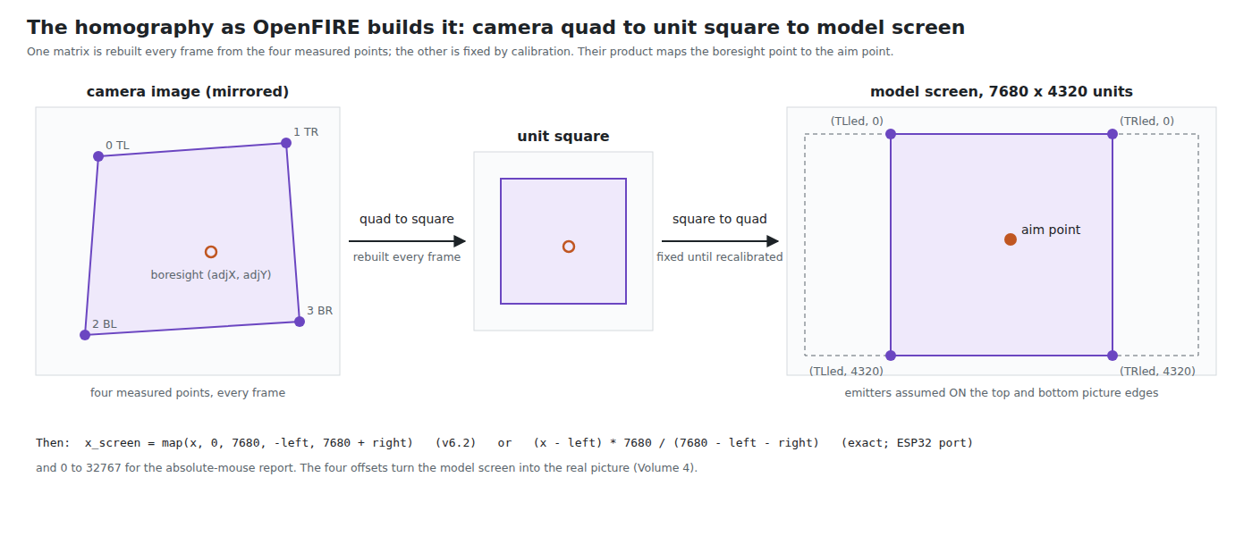
3.1 The Map Being Computed
A homography maps a point (x, y) in one plane to (x′, y′) in another by
x′ = (h11·x + h12·y + h13) / (h31·x + h32·y + h33)
y′ = (h21·x + h22·y + h23) / (h31·x + h32·y + h33)
Written with homogeneous coordinates it is one 3 × 3 matrix H acting on (x, y, 1), followed by division by the third component. Multiplying every entry of H by the same number changes nothing, so H has eight free parameters, and fixing h33 = 1 is the usual way to remove the ninth. When h31 = h32 = 0 the denominator is constant and the map is affine; the two bottom-row entries are the perspective, the part that lets a rectangle become a trapezoid.
The light gun needs the map from the camera’s image plane to the screen plane. Every frame it has four correspondences: four measured image points and the four places on the screen where the emitters are known (or assumed) to be. Each gives two equations, so four give eight, which is exactly enough.
3.2 The General Method: the Direct Linear Transform
Multiplying out the denominators and setting h33 = 1, each correspondence (x, y) → (x′, y′) gives two equations that are linear in the eight unknowns:
h11·x + h12·y + h13 − h31·x·x′ − h32·y·x′ = x′
h21·x + h22·y + h23 − h31·x·y′ − h32·y·y′ = y′
Stack four correspondences and the result is an 8 × 8 linear system, solvable by Gaussian elimination. This is the direct linear transform (DLT). The textbook form keeps all nine entries, writes the equations as A·h = 0 with A 2N × 9 for N points, and takes h as the right singular vector of A with the smallest singular value. That form takes any number of points (more than four gives a least-squares fit) and does not assume h33 ≠ 0, which matters when the true h33 is near zero.
Two practical rules come with the DLT. Normalise first: translate each point set so its centroid is at the origin and scale it so the mean distance from the origin is √2, solve, then undo the normalisation. Without it, the columns of A differ in magnitude by the square of the coordinate range (products like x·x′ reach 10⁷ while the 1s stay 1), and the solution loses precision in single precision. And check the configuration: if three of the four points are collinear the system is singular, and if they are nearly collinear it is ill-conditioned and small noise moves the answer a long way.
On a microcontroller an 8 × 8 elimination is about 200 multiply-adds and eight divides, and an SVD is far more. The firmware family uses neither.
3.3 The Closed Form in OpenFIRE
OpenFIRE_Perspective.cpp states its ancestry in its header (lines 13–17): “Derived from Wiimote Whiteboard library … Ported from Johnny Lee’s C# WiiWhiteboard project (Warper.cs file)”. The method in Lee’s file is the one Paul Heckbert set out in his 1989 thesis on texture mapping: never solve for a general four-point map directly; instead, map the unit square to each quadrilateral in closed form, and compose.
3.3.1 Square to quadrilateral
Send the unit square’s corners (0,0), (1,0), (1,1), (0,1) to the quadrilateral’s corners (x0,y0), (x1,y1), (x2,y2), (x3,y3). Put the matrix in row-vector form, [x′ y′ w] = [u v 1] · M, with
    | a  d  g |
M = | b  e  h |
    | c  f  1 |
The corner (0,0) gives c = x0, f = y0 directly. The other three corners give six equations. Define
dx1 = x1 − x2    dx2 = x3 − x2    sx = x0 − x1 + x2 − x3
dy1 = y1 − y2    dy2 = y3 − y2    sy = y0 − y1 + y2 − y3
sx and sy measure how far the quadrilateral is from a parallelogram: they are zero exactly when it is one, and then g = h = 0 and the map is affine. Otherwise g and h solve a 2 × 2 system, by Cramer’s rule:
g = (sx·dy2 − dx2·sy) / (dx1·dy2 − dx2·dy1)
h = (dx1·sy − sx·dy1) / (dx1·dy2 − dx2·dy1)
a = x1 − x0 + g·x1      b = x3 − x0 + h·x3
d = y1 − y0 + g·y1      e = y3 − y0 + h·y3
That is computeSquareToQuad(), lines 26–59, term for term. It costs two divides and about thirty other operations, with no iteration and no pivoting.
3.3.2 Quadrilateral to square
The inverse map is the inverse matrix. computeQuadToSquare() (lines 61–104) builds M for the quadrilateral and then inverts it by the adjugate: nine cofactors A to I, a determinant a·A + b·D + c·G, one divide for its reciprocal and nine multiplies. A 3 × 3 adjugate inverse is exact in exact arithmetic and needs no pivoting.
3.3.3 The composition
warp() (lines 120–135) does three things:
- On the first frame after calibration (
if (!init), line 121), it builds the square-to-quad matrix for the model screen’s four emitter positions and keeps it (dstmatrix). For the square layout these are (TLled, 0), (TRled, 0), (TLled, 4320), (TRled, 4320) in a 7680 × 4320 model screen (Open-Source Firmware, Volume 2). - Every frame, it builds the quad-to-square matrix for the four camera points (
srcmatrix) and multiplies:multMats(srcmatrix, dstmatrix, warpmatrix). In row-vector form, camera point → unit square → model screen is one matrix product, srcmatrix × dstmatrix. - It pushes one point through the product, the boresight (
srcX, srcY, set at calibration, Volume 4):
r0 = srcX·W[0] + srcY·W[4] + W[12];
r1 = srcX·W[1] + srcY·W[5] + W[13];
r3 = srcX·W[3] + srcY·W[7] + W[15];
dstX = (r0/r3);   dstY = floorf(r1/r3);
The matrices are held in 4 × 4 arrays laid out like OpenGL’s (entry 3 is g, 7 is h, 12 and 13 are c and f, 15 is the 1), a layout carried over from the code it was ported from. Only nine of the sixteen entries are ever non-trivial.
Because the homography from four points is unique, the product is the homography from the camera’s quadrilateral to the model screen’s, however it was assembled. The simulation confirms it: with an ideal camera on the bore and the exact offset map of Volume 4, the aim error is zero to within 10⁻¹² mm at every distance, angle and roll tested (aim_maths.py section 3).
3.4 The Corner Order and the “Hourglass”
Heckbert’s construction assumes the four corners are given in cyclic order around the quadrilateral: (0,0), (1,0), (1,1), (0,1). OpenFIRE v6.2 passes them as top-left, top-right, bottom-left, bottom-right (OpenFIREcommon.cpp lines 665–672), which goes around the quadrilateral as a figure of eight. The square’s edge from (1,0) to (1,1) is sent along a diagonal, from top-right to bottom-left.
The ESP32 port calls this the “hourglass bug” (Bug Clessidra) and reorders the corners to a closed perimeter before building either matrix, with the comment that the algorithm “explodes if the vertices of the quadrilateral cross in an X” (OpenFIRE_Perspective_Advanced.cpp lines 182–189).
Is it a bug in v6.2? In exact arithmetic, no. A homography exists for any four points with no three collinear, whatever order they are listed in; both matrices use the same crossed order, so the crossing cancels in the product, and the product is still the unique camera-to-screen homography. But the intermediate map is strange. With a crossed order, the two “sides” from top-right to bottom-left and from bottom-right to top-left are the quadrilateral’s diagonals, which meet at its centre; the lines x = 1 and x = 0 of the square meet only at infinity, so the quadrilateral’s centre is the image of a point at infinity. Push the boresight through the quad-to-square matrix alone while aiming at the middle of the screen and the homogeneous coordinate is exactly zero: the simulation divides by zero (aim_maths.py section 18). With the cyclic order the same coordinate is 1.0000.
v6.2 never evaluates the intermediate point. It multiplies the matrices first and projects once through the product, and the product is well-behaved: the simulation finds no loss of precision even for dead-centre aims (3.5). So the crossed order is harmless as v6.2 uses it and would be fatal in any rewrite that projects through the two maps in turn. The port’s reordering costs nothing and removes the trap; a fork should adopt it.
3.5 Conditioning and Precision
The RP2040 has no floating-point hardware, and the RP2350’s Cortex-M33 cores have single-precision only, so the question is whether float32 is enough. The simulation re-runs the whole v6.2 chain with every intermediate result rounded to float32 and compares it with float64:
Table 1 — The RP2040 has no floating-point hardware, and the RP2350's Cortex-M33 cores have single-precision only, so the question is whether float32 is enough. The simulation re-runs the whole v6.2 chain with every intermediate result rounded to float32 and compares it with float64
| Camera | Cases (positions × targets) | Worst difference |
|---|---|---|
| Wii-class (internal range 0–4095) | 36, out to 5 m and 45° | 0.47 µm on the screen |
| PAJ7025R2 (range 0–4095) | 36 | 0.78 µm |
aim_maths.py sections 10 and 18. A 1080p pixel on a 55-inch picture is 634 µm.
Float32 is more than adequate, by a factor of about a thousand. The reason is that Heckbert’s closed form never forms the large products a raw DLT does: it works with differences of coordinates (dx1, sx) whose magnitudes are a few thousand, and its largest intermediate terms are products of two of them, up to about 3 × 10⁸, which float32 holds to a relative 6 × 10⁻⁸, leaving ample room for the cancellation in the determinant. The ESP32 port scales every coordinate by 10⁻⁴ before the matrices are built (NORM_SCALE = 10000, OpenFIRE_Perspective_Advanced.h line 47; applied at lines 211–214 and 240–243). Its comment says the scale “limits losses of precision in the homographies”; the simulation suggests there was little to lose, but the scaling is harmless and would matter more for a camera with a larger range or a raw DLT.
One detail of v6.2 deserves a note: float idet = 1.0 / (a * A + b * D + c * G); (line 83). 1.0 is a double literal, so the float sum is promoted, divided in double precision and converted back. It is numerically harmless and costs about 250 cycles on an RP2040 (the bootrom’s double divide is 183 cycles against 71 for float, datasheet Table 169, plus two conversions). 1.0f removes it.
3.6 Degenerate Input and the Missing Guards
The closed form divides three times: by dx1·dy2 − dx2·dy1 (twice, in computing g and h) and by the determinant in the inverse, then by r3 in the projection. Each is zero when the geometry degenerates:
- Three points collinear in the image. The quadrilateral has collapsed to a triangle or a line. This happens when two blobs merge, when a reflection is mistaken for an emitter, or when the missing-point rebuild (Volume 2, 2.7) puts a corner in a bad place.
- The boresight on the vanishing line. r3 = 0 when the boresight maps to infinity on the model screen, which means the gun is pointing parallel to the screen. It cannot happen with all four emitters in view, but a rebuilt corner can produce it.
v6.2 checks none of these. A divide by zero in float produces infinity or NaN, and what becomes of it depends on the target: the RP2040 bootrom’s float-to-integer routine treats NaN as infinity and clamps to the integer range (datasheet §2.8.3.2), so on a Pico the cursor slams to a corner for a frame rather than crashing. The ESP32 port adds every guard: it rejects a destination whose determinant is not finite or is zero (lines 49–50), a source whose perspective term is singular (line 82) or whose inverse determinant is below 10⁻⁸ (line 101), a quadrilateral whose area is below a threshold (line 196), a near-zero r3 (line 262) and a non-finite result (line 270), and in each case keeps the last good output. That is the right behaviour, and a one-frame hold is invisible to a player.
3.7 What It Costs per Frame
The RP2040 does float arithmetic in software, through optimised routines in its boot ROM that the Pico SDK substitutes for the compiler’s own. The datasheet gives their average cost (Table 169, version 2 and 3 ROMs): add 71 cycles, subtract 74, multiply 58, divide 71, square root 63, atan2 667, sine 577, cosine 587. Counting the operations in the v6.2 code and pricing them:
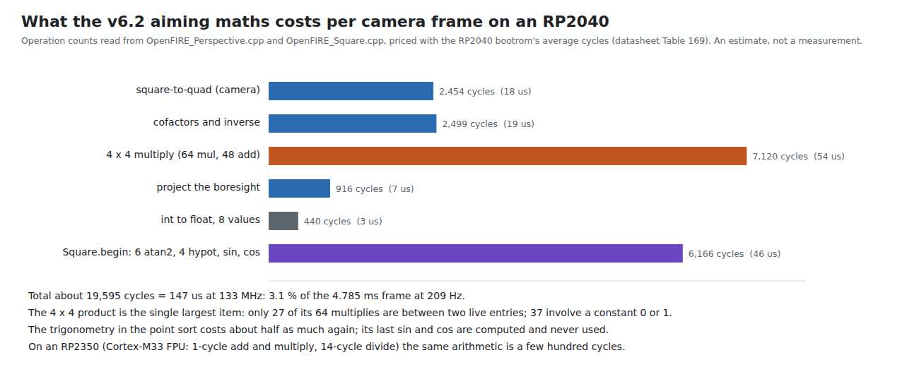
Table 2 — 3.7 What It Costs per Frame
| Part | Operations | Cycles | µs at 133 MHz |
|---|---|---|---|
| Square-to-quad for the camera points | 22 add/sub, 12 mul, 2 div | ≈ 2,450 | 18 |
| Cofactors and inverse | 11 add/sub, 26 mul, 1 double divide | ≈ 2,500 | 19 |
| 4 × 4 product | 64 mul, 48 add | 7,120 | 54 |
| Projection | 6 mul, 6 add, 2 div | 916 | 7 |
| Integer-to-float conversions | 8 | 440 | 3 |
| Point sort’s trigonometry (6 atan2, 4 hypot, an unused sin and cos) | ≈ 6,170 | 46 | |
| Total | ≈ 19,600 | ≈ 147 |
An estimate from operation counts, not a measurement. The SDK note in the datasheet says real-world timings can differ, and function-call overhead, loads and stores are not counted. The square-to-quad for the destination is built once per calibration and not counted.
At 3 % of a 4.785 ms frame, the maths is not a bottleneck on core 0, which spends far more time waiting for the I²C read (Open-Source Firmware, Volume 2). Two items are pure waste. Of the 64 multiplies in the 4 × 4 product, only 27 are between two entries that can be other than 0 or 1; the other 37 multiply by a constant, and each still costs a 58-cycle call. And the last lines of OpenFIRE_Square::begin() (lines 234–236) compute a sine and a cosine into local variables that are never used — 1,164 cycles a frame. (Whether the compiler removes them depends on whether it treats the bootrom calls as free of side effects; it was not checked.)
On an RP2350 the Cortex-M33’s floating-point unit executes add, subtract and multiply in one cycle each and divide and square root in 14 (RP2350 datasheet §3.7). The same arithmetic, without the trigonometry, is a few hundred cycles, around 2 µs at 150 MHz. The question of cost disappears.
3.8 Making It Cheaper, and Fixed Point
Nothing needs to be cheaper at 209 Hz. If a fork ever runs two cameras, or a camera at a much higher rate, or wants to free core 0 for something else, the savings in order of value are:
- A 3 × 3 product instead of 4 × 4. 27 multiplies and 18 adds instead of 64 and 48: about 4,300 cycles saved. The ESP32 port already does this (lines 112–122).
- Delete the unused sine and cosine in
OpenFIRE_Square::begin(): about 1,160 cycles. - Refresh the sort’s angles less often. The four atan2 and hypot calls that keep the missing-point rebuild current need not run every frame; every fifth would do, since they only matter when a point disappears.
- Skip the full product. Only one point is ever projected, so the three dot products of the boresight with the product’s columns can be formed directly from the two matrices, without the product: 18 multiplies instead of 27.
Fixed point looks attractive on a core without an FPU and is less so in practice. The coordinates are 12 to 14 bits; dx1·dy2 and its relatives are 26 to 28 bits; the cofactors of the inverse are products of three coordinates, about 40 bits. A fixed-point version therefore needs 64-bit intermediates, and the Cortex-M0+ has only a 32 × 32 → 32-bit multiply, so each 64-bit product is a library call of several instructions. The quantities also span very different ranges — g and h are of order 10⁻⁴ per coordinate unit while a and e are of order 1 — so each needs its own scaling, worked out by hand and re-checked whenever a camera with a different range is added. The bootrom’s float multiply, at 58 cycles, is not far from what a careful 64-bit fixed-point multiply costs, and float32’s precision has been shown to be a thousand times better than needed. On an RP2350 there is no case for fixed point at all.
3.9 Why This, and Why Not the Others
Proposed: keep Heckbert’s closed form in float32, as v6.2 has it, with the ESP32 port’s cyclic corner order, its degenerate-input guards and its 3 × 3 product, and 1.0f at line 83. These are code-hygiene changes for Our Firmware, not accuracy fixes.
Table 3 — 3.9 Why This, and Why Not the Others
| Option | Why not, or why |
|---|---|
| Heckbert closed form, float32 | Chosen: exact for four points, error under 1 µm in float32 (3.5), about 3 % of a frame on an RP2040 and negligible on an RP2350 (3.7) |
| General DLT with Gaussian elimination | Same answer for four points at several times the cost; needs normalisation to be safe in float32 |
| DLT by SVD, least squares over more than four points | The right tool for five or more emitters on a PixArt camera (Volume 2, 2.7); too heavy and pointless for four |
| Fixed point on the RP2040 | Needs 64-bit intermediates and per-quantity scaling; little or no faster than the bootrom float (3.8) |
| Keep v6.2’s crossed corner order | Harmless as v6.2 uses it, but a trap for any change that projects through the intermediate square (3.4) |
| Keep v6.2 without guards | A degenerate frame sends the cursor to a corner; holding the last good value is invisible (3.6) |
3.10 What Could Not Be Verified
- The cycle costs are estimates from operation counts and the datasheet’s average bootrom timings; nothing was timed on a Pico.
- Whether the compiler eliminates the unused sine and cosine.
- Lee’s original
Warper.cswas not read; the derivation is checked against OpenFIRE’s port of it, which credits it. - Heckbert’s thesis (Fundamentals of Texture Mapping and Image Warping, UC Berkeley, 1989) is cited for the construction from general knowledge of it; it was not re-read for this dive. The construction itself is verified against the code and the simulation.
Sources
- TeamOpenFIRE,
OpenFIRE-Firmwareat8b651a25(v6.2):libraries/OpenFIREPosition/OpenFIRE_Perspective.cpp,OpenFIRE_Square.cpp;OpenFIREmain/OpenFIREcommon.cpp— read 2026-10-19. - Alessandro Satanassi,
OpenFIRE-Firmware-ESP32atf6458fc9:lightgun/lib/OpenFIREPosition/OpenFIRE_Perspective_Advanced.cppand.h— read 2026-10-19. - Raspberry Pi Ltd, RP2040 Datasheet, §2.8.3.2 and Table 169 (bootrom floating-point routines); RP2350 Datasheet, §3.7 (Cortex-M33 FPU timing). Central Library copies.
- Own simulation,
04-templates/aim_maths.py, sections 3, 10, 14 and 18, run 2026-10-19.
Comments (0)