Aiming Maths and Calibration · Volume 2
Naming the Points, and the Models Before the Homography — Two Points, Roll, Scale and What They Cannot Correct
How the firmware decides which dot is which, the roll at which that fails, and the two simpler mappings the open firmware family used before it adopted perspective — read from the Samco and Prow source, and measured against the homography in simulation
2.1 Points Arrive Without Names
A multi-object tracking camera reports blobs in slots, and the slot a blob occupies says nothing about which emitter made it (IR Point Tracking, Volume 1 describes the slot behaviour). Before any geometry, the firmware must decide which reported point is the top-left emitter, which the top-right and so on. If it gets that wrong, everything after it is wrong in a way no calibration can repair: a homography fitted to mislabelled corners describes a screen that has been flipped or twisted.
The open firmware family has used two answers. Samco’s two-emitter sketches order the pair by X. Samco’s four-emitter sketches, Prow Enhanced and OpenFIRE assign each point to a quadrant around the mean of all four. Each answer comes with a model of the screen, and the two go together.
2.2 Two Points: Samco 2IR
The two-emitter Samco sketch (Samco_2IR/Samco_2.0_2IR/Samco_2.0_2IR.ino) is the simplest complete light-gun aiming code in the family, and it is short enough to read whole.
Naming. Lines 213–230 compare the two X values and call the larger “one” and the smaller “two”. If they are equal it gives up and returns a fixed nonsense value. Nothing else identifies the emitters. Because the camera’s X is mirrored (Volume 1, 1.3), “one” is the left-hand emitter as the player sees it.
The position. Lines 232–233 compute the midpoint of the two points and rotate it about the image centre (512, 384) by minus the angle of the line joining them:
finalX = 512 + cos(−a)·(mx − 512) − sin(−a)·(my − 384)
finalY = 384 + sin(−a)·(mx − 512) + cos(−a)·(my − 384)
with a = atan2(twoY − oneY, twoX − oneX), (mx, my) the midpoint
Calibration. Two shots. The sketch moves the cursor to (300, 200) and records finalX, finalY when the trigger is pulled (lines 142–149); then to (res_x − 300, res_y − 200), the bottom-right, and records again (lines 161–168).
The output. A straight-line map between the two recorded positions and the two cursor targets, independently on each axis (lines 185–186):
MoveXAxis = map(finalX, xLeft, xRight, 300, res_x − 300);
MoveYAxis = map(finalY, yTop, yBottom, 200, res_y − 200);
Two shots give four numbers, an offset and a gain on each axis, and that is exactly what the map has. It is a complete and consistent method for one assumption: that the image position of the bar moves in proportion to where the gun points on the screen, by the same proportion at every distance.
2.3 What Roll Correction Does
The rotation in lines 232–233 earns its place. When the player cants the gun, the camera rolls with it, and the whole image turns about the image centre. The bar’s midpoint swings around the centre, and without correction a canted gun aimed at the middle of the screen would report a point off to one side. Rotating the midpoint back by the bar’s measured angle undoes that: it computes where the midpoint would be if the camera were level.
Two properties of the correction matter. It is exact only for rotation about the image centre, which a canted camera with a centred lens provides; and it needs the line between the points to be a reliable level reference, which it is only while the bar is level on the wall and the player is not looking at it obliquely from above or below. And it assumes it can tell the emitters apart: past 90° of cant the X order of the two points reverses, the “left” emitter becomes the right one, and the measured angle jumps by 180°. A two-point gun works to a little under 90° of cant and fails abruptly beyond it.
2.4 What Two Points Cannot Correct
Where a player stands changes the mapping, and two points have no way to know. The image position of the bar is set by the angle between the camera’s axis and the bar; the screen position the gun points at is that angle times the distance. A linear map calibrated at distance D_cal therefore has the right gain at D_cal only. Aiming at a point s millimetres from the calibrated centre from distance D, the cursor lands at s · D_cal/D, so the miss is
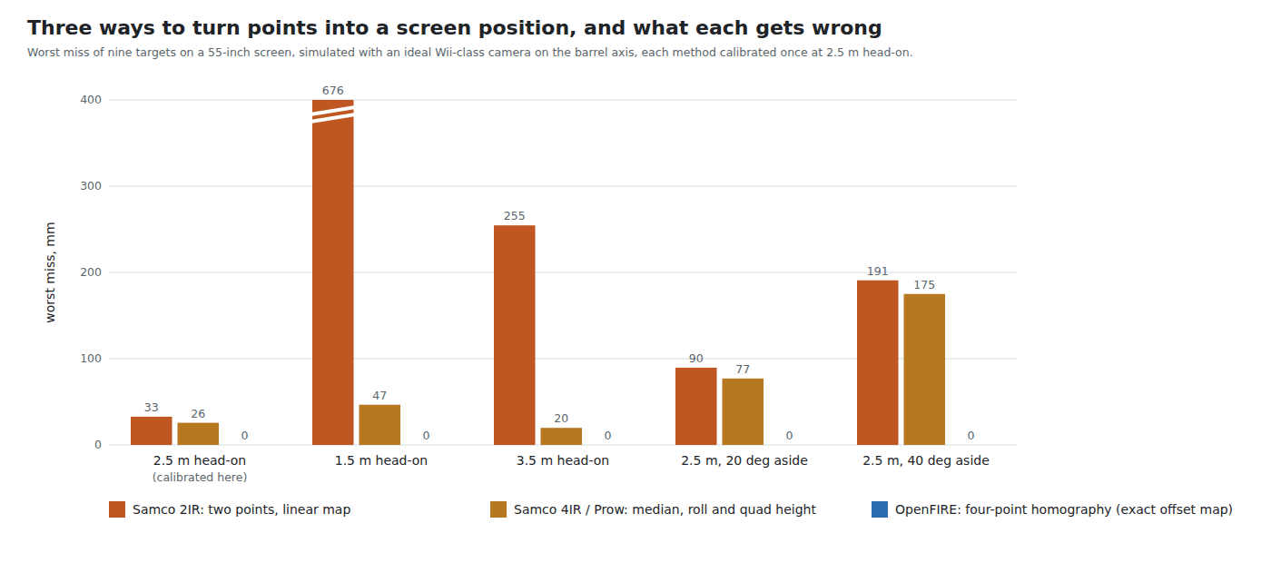
miss ≈ s · (D_cal / D − 1)At the edge of a 55-inch picture (s ≈ 550 mm) calibrated at 2.5 m, the cursor lands 365 mm past the edge from 1.5 m and 157 mm short of it from 3.5 m, before any perspective error. The simulation, which adds the perspective error IR Point Tracking, Volume 3 quantifies for a bar of this kind, gives worse:
Table 1 — At the edge of a 55-inch picture (s ≈ 550 mm) calibrated at 2.5 m, the cursor lands 365 mm past the edge from 1.5 m and 157 mm short of it from 3.5 m, before any perspective error. The simulation, which adds the perspective error [IR Point Tracking, Volume 3](/light-guns/sensing-and-aiming/ir-point-tracking/vol-3/) quantifies for a bar of this kind, gives worse
| Player position, after calibrating at 2.5 m head-on | Samco 2IR, worst of 9 targets |
|---|---|
| 2.5 m head-on (where it was calibrated) | 33 mm |
| 2.0 m | 257 mm |
| 1.5 m | 676 mm |
| 3.0 m | 148 mm |
| 3.5 m | 255 mm |
| 2.5 m, 20° to the side | 90 mm |
| 2.5 m, 40° to the side | 191 mm |
aim_maths.py sections 8 and 9; ideal Wii-class camera on the bore, bar 200 mm wide, 30 mm under the picture.
The 33 mm at the calibration position is the perspective error the two corner shots cannot remove: the map is exact at the two calibrated corners and wrong elsewhere, worst at the corners it did not see. The distance error is the larger problem: a two-point gun is accurate only from the spot where it was calibrated.
The separation of the two points could measure distance — it is inversely proportional to it — and the Wii Remote is described as doing so (IR Point Tracking, Volume 3 §3.3). But the separation also shrinks with the cosine of the angle from which the bar is seen, so a player who steps sideways looks as if he has stepped back. Samco 2IR does not use the separation at all.
2.5 Four Points as a Similarity: Samco 4IR and Prow Enhanced
The four-emitter Samco sketches and Mike Lynch’s Prow Enhanced fork, which became the foundation of OpenFIRE (Open-Source Firmware, Volume 1), took the next step: four emitters, and a distance term. They did not yet use a homography.
Position and roll. Prow’s SamcoPositionEnhanced.cpp sorts the points into quadrants (2.6), takes their mean (medianX, medianY; despite the name it is a mean, lines 192–198) and rotates it about the image centre by the mean angle of the top and bottom edges (lines 233–237) — the same roll correction as Samco 2IR, with a sturdier angle estimate.
Distance. The apparent height of the quadrilateral, h(), the mean of its left and right side lengths, scales the output range (SamcoEnhanced.ino lines 893–896):
halfHscale = h · xScale / 2;
moveXAxis  = map(finalX, xCenter + halfHscale, xCenter − halfHscale, 0, MouseMaxX);
and the same with yScale for Y. As the player steps back, h shrinks and the range shrinks with it, which is exactly the D_cal/D correction Samco 2IR lacked. The model is a similarity: position, roll and scale.
Calibration. The sketch’s own instructions (lines 36–55) describe it: shoot the centre and hold the trigger for a third of a second, then “use A/B buttons … to adjust mouse vertical range … Track the top and bottom edges of the screen while adjusting”, then the same horizontally. CalCenter() (lines 993–1034) averages every camera frame for up to 333 ms — about 70 frames at 209 Hz — into xCenter and yCenter. CalVert() and CalHoriz() let the player trim yScale and xScale by eye, and nudge the centre with the D-pad. Four numbers again, two of them found by the player watching the cursor.
What a similarity cannot represent is the perspective of a screen seen from an angle or aimed at near a corner. In the simulation, with the scales set to the values that put the cursor exactly on the edges at the calibration position (xScale 1.672, yScale 0.940):
Table 2 — What a similarity cannot represent is the perspective of a screen seen from an angle or aimed at near a corner. In the simulation, with the scales set to the values that put the cursor exactly on the edges at the calibration position (xScale 1.672, yScale 0.940)
| Player position | Prow / Samco 4IR similarity, worst of 9 targets |
|---|---|
| 2.5 m head-on (calibrated) | 26 mm |
| 1.5 m head-on | 47 mm |
| 3.5 m head-on | 20 mm |
| 2.5 m, 20° aside | 77 mm |
| 2.5 m, 40° aside | 175 mm |
The distance term works: from 1.5 m and 3.5 m the error is now tens of millimetres, not hundreds. The remaining error is perspective, and it grows quickly with the angle from which the screen is seen. That is what OpenFIRE’s switch to Johnny Lee’s homography fixed, and the right-hand bars in the figure at the top of this volume are zero at every position for that reason.
2.6 The Median Sort and Its Roll Limit
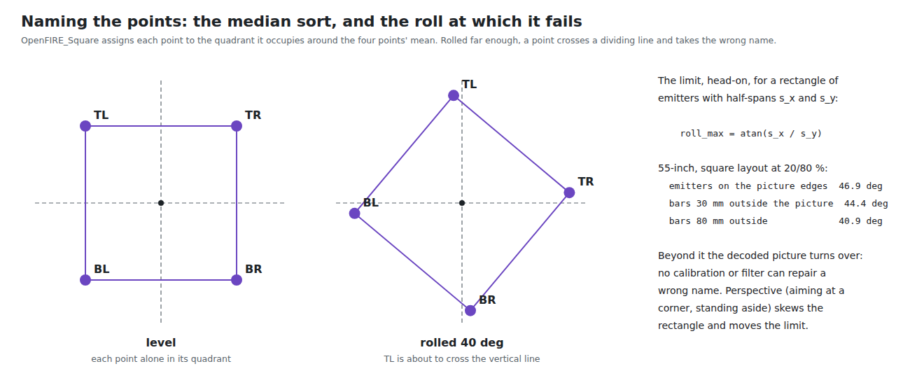
OpenFIRE kept Prow’s way of naming the points (OpenFIRE_Square.cpp lines 99–124, credited to Sam Ballantyne). Each reported point is compared with the previous frame’s mean of all four: above and left is top-left, above and right is top-right, and so on. Open-Source Firmware, Volume 2 describes it; here the question is when it fails.
Take a rectangle of emitters with half-spans s_x across and s_y down, seen head-on and rolled by θ about its centre. The top-left point, at (−s_x, −s_y), moves to x = −s_x cos θ + s_y sin θ, which reaches the vertical line through the mean when
θ_max = atan(s_x / s_y)For the square layout on a 55-inch picture (emitters at 20 % and 80 % of the width, so s_x = 365 mm):
Table 3 — For the square layout on a 55-inch picture (emitters at 20 % and 80 % of the width, so sx = 365 mm)
| Where the bars sit | s_y | Roll limit, head-on |
|---|---|---|
| Emitters on the picture’s top and bottom edges | 342 mm | 46.9° |
| Bars 30 mm outside the picture | 372 mm | 44.4° |
| Bars 80 mm outside the picture | 422 mm | 40.9° |
The “±45°” usually quoted (IR Point Tracking, Volume 3 §3.6) is therefore the right order but depends on the emitter rectangle’s shape: bars set further outside a wide picture make the rectangle taller and the limit lower. Viewing the screen at an angle, or aiming toward a corner, turns the rectangle into a trapezoid and moves the limit for one corner up and another down. Past it, the decoded picture turns over and the cursor jumps; no calibration and no filter can repair a wrong name.
For a light gun that is held upright this is a non-issue in play. It is the reason a gun canted hard for a “gangster” pose jumps, and the reason a camera mounted rotated in the barrel by more than the limit cannot be fixed in software without changing the sort (Open-Source Firmware, Volume 3 notes the camera’s “TOP” mark for this reason).
The diamond layout uses a different routine (OpenFIRE_Diamond.cpp), which compares the points with the mean offset by half the diamond’s width and height and carries a tilt flag; its limit was not derived here.
2.7 When a Point Is Missing
When one emitter leaves the camera’s field or is hidden, OpenFIRE rebuilds it from its neighbour, the last good length of the side between them and the last good angle, refreshed only after five consecutive frames with all four visible (OpenFIRE_Square.cpp lines 131–187 and 202–231; Open-Source Firmware, Volume 2 describes it and IR Point Tracking, Volume 3 §3.7 the geometry).
Mathematically the rebuild says: assume the quadrilateral is still the shape it was when last seen whole, translated with the visible points. That is an affine assumption about a perspective shape. It holds well when the gun only rotates — aiming into a corner from where the player stands changes the shape slowly — and degrades when the player moves while a point is hidden. With three real points and one rebuilt, the homography is computed from four points as usual, and any error in the rebuilt corner goes straight into the aim, weighted most heavily near that corner. A fifth emitter would let the firmware fit the homography by least squares from whichever four or more it sees, with no rebuild at all; the Wii-class camera reports only four objects, but the PixArt cameras report sixteen (IR Point Tracking, Volume 3 §3.9). That is a candidate for Our Firmware once the R2 or R3 is in use.
2.8 Why This, and Why Not the Others
Proposed: keep OpenFIRE’s four-point homography with its median sort. Do not use a two-point or similarity model for any mode of this build.
Table 4 — Proposed: keep OpenFIRE's four-point homography with its median sort. Do not use a two-point or similarity model for any mode of this build.
| Option | Why not, or why |
|---|---|
| Four-point homography (OpenFIRE) | Chosen: exact at every distance, angle and roll within the sort’s limit (simulation, and IR Point Tracking, Volume 3); already in the firmware |
| Two points, linear map (Samco 2IR) | 33 mm wrong where calibrated and hundreds of millimetres once the player moves (2.4) |
| Two points with distance from their separation (Wii-style) | Separation confuses sideways and backwards movement; still no perspective |
| Four points as a similarity (Samco 4IR, Prow) | Fixes distance, but 26 mm wrong where calibrated and 175 mm from 40° aside (2.5) |
| A sort that tolerates any roll (e.g. naming by the cyclic order of the convex hull, starting from the point nearest the top bar’s known shape) | Possible, but a light gun is held upright, and an asymmetric emitter pattern would be needed to tell upright from inverted at all. Not worth a change to the firmware’s most fragile routine |
| Five or more emitters with a least-squares fit | Not possible on the Wii-class camera (four objects); worth revisiting with a PixArt camera (2.7) |
2.9 What Could Not Be Verified
- The roll limit of the diamond layout’s sort.
- How the Wii Remote’s own software uses point separation and its motion sensors.
- Whether the simulation’s ideal scales for Prow (1.672 and 0.940) resemble what players dial in; a player adjusting by eye will land somewhere near them.
Sources
- Sam Ballantyne,
IR-Light-Gun(Samco) at929490f3:Samco_2IR/Samco_2.0_2IR/Samco_2.0_2IR.ino, https://github.com/samuelballantyne/IR-Light-Gun — read 2026-10-19. - Mike Lynch,
ir-light-gun(Prow Enhanced) ataeab7d1c:libraries/SamcoPositionEnhanced/SamcoPositionEnhanced.cpp,SamcoEnhanced/SamcoEnhanced.ino, https://github.com/Prow7/ir-light-gun — read 2026-10-19. - TeamOpenFIRE,
OpenFIRE-Firmwareat8b651a25(v6.2):libraries/OpenFIREPosition/OpenFIRE_Square.cpp,OpenFIRE_Diamond.cpp— read 2026-10-19. - Own simulation,
04-templates/aim_maths.py, sections 8, 9 and 17, run 2026-10-19.
Comments (0)