Aiming Maths and Calibration · Volume 5
Parallax — Why the Camera and the Sight Line Disagree, and by How Much
The error a camera beside the aiming line makes away from the distance it was calibrated at, derived and confirmed in simulation; why tilting the camera cannot fix it; the ESP32 port's dormant dynamic correction and the form it should take; and what it means for where the camera goes in an MP7 shell
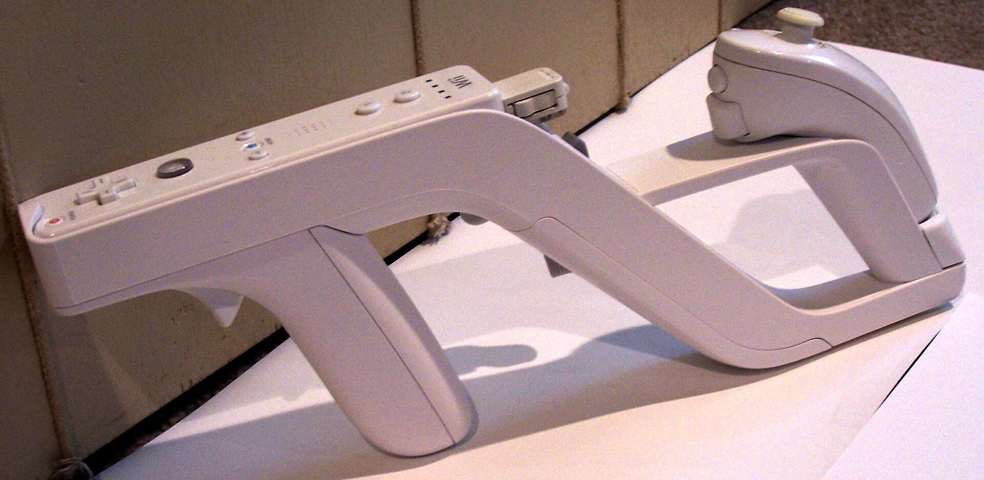
5.1 The Gun Has Two Axes
A light gun has the line the player aims along and the line the camera looks along, and they are never the same line. The camera sits in the barrel or on the frame; the player’s eye looks along the sights, or along the top of the gun, or, firing from the hip, along wherever the gun seems to point.
For a light gun the line that matters is the sight line, not the physical bore: there is no projectile, so the “shot” lands wherever the player believes the gun is pointing, and a player who aims carefully believes the sights. (A player who points from the hip aims with the whole gun, and the reference becomes vaguer, which is one reason the hip-firing player rarely notices a few millimetres.) In what follows, the “aiming line” is whichever line the player aims with, and d is the camera’s perpendicular distance from it.
Volume 1 (1.5) introduced the boresight, the image point where the aim point appears. This volume is about the fact that, with d not zero, that point moves with distance.
5.2 The Error, Derived
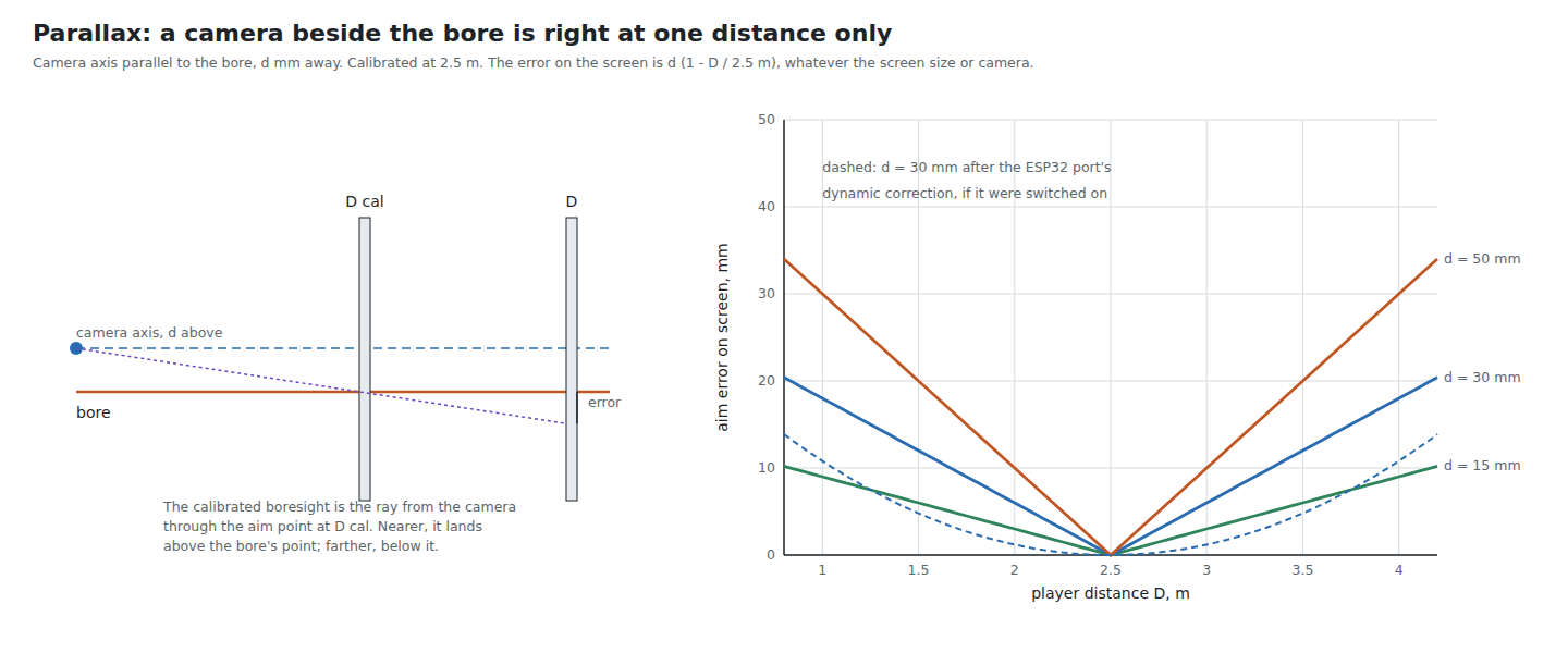
Put the camera’s centre of projection a perpendicular distance d from the aiming line, with its optical axis parallel to it. The player aims at a point P on the screen a distance D away along the aiming line. In the camera’s frame, P lies a distance D ahead and d to one side, so it appears at an angle d/D off the camera’s axis (small angles), and its image is displaced from the image centre by
Δb(D) = f · d / Din reported units. That is the boresight, and it depends on D.
Calibration (Volume 4) records the boresight at one distance, D_cal: b_cal = f · d / D_cal. At any other distance the firmware pushes b_cal through the homography and gets the point the camera sees along that ray. The ray leaves the camera, crosses the aiming line at D_cal, and at distance D sits to the other side of it by
error(D) = d · (1 − D / D_cal)on the screen, in the same units as d. Nearer than D_cal the cursor lands on the camera’s side of the aim point; farther, on the far side. Three properties make this formula worth memorising:
- It does not depend on the camera. Field of view, resolution and lens cancel; the Wii-class camera and the R3 make the same parallax error.
- It does not depend on the screen size. It is a distance in millimetres, the same on a 32-inch monitor as on a projector screen, so on a small screen it is a larger fraction of the picture.
- It is bounded by d between D = 0 and D = 2 · D_cal, and grows without limit beyond.
The simulation, which builds the full geometry and runs v6.2’s pipeline with the exact offset map, agrees to within a millimetre:
Table 1 — The simulation, which builds the full geometry and runs v6.2's pipeline with the exact offset map, agrees to within a millimetre
| d | 1.0 m | 1.5 m | 2.0 m | 2.5 m (calibrated) | 3.0 m | 4.0 m |
|---|---|---|---|---|---|---|
| 15 mm | 9.3 (9.0) | 6.1 (6.0) | 3.1 (3.0) | 0.3 (0) | 3.3 (3.0) | 9.2 (9.0) |
| 30 mm | 18.6 (18.0) | 12.3 (12.0) | 6.3 (6.0) | 0.7 (0) | 6.5 (6.0) | 18.4 (18.0) |
| 50 mm | 31.1 (30.0) | 20.5 (20.0) | 10.5 (10.0) | 1.1 (0) | 10.9 (10.0) | 30.6 (30.0) |
Worst of nine targets, mm, simulation (formula in brackets); aim_maths.py section 5. The small excess over the formula is 5.5’s second-order term.
5.3 Worked Numbers
On a 55-inch picture a 1080p pixel is 0.63 mm. Calibrating at 2.5 m and playing anywhere from 1.5 m to 4 m, the worst error is 0.6 · d:
Table 2 — On a 55-inch picture a 1080p pixel is 0.63 mm. Calibrating at 2.5 m and playing anywhere from 1.5 m to 4 m, the worst error is 0.6 · d
| d | Worst error, 1.5–4 m | In 1080p pixels, 55-inch | In 1080p pixels, 32-inch |
|---|---|---|---|
| 5 mm | 3 mm | 5 px | 8 px |
| 15 mm | 9 mm | 14 px | 24 px |
| 30 mm | 18 mm | 28 px | 49 px |
| 50 mm | 30 mm | 47 px | 81 px |
The 32-inch column uses 0.37 mm per pixel (a 708 mm-wide picture). These are pure arithmetic from the formula.
For scale: the game targets that matter most — a head in a shooting gallery, a small button in a menu — are tens of pixels across, and IR Point Tracking, Volume 3 puts the error of a two-point method at 45 to 285 mm. Parallax with d of 15 mm is small by comparison. It becomes the largest error in a well-calibrated four-point gun once the lens and the offset map are right (Volume 7), which is why it is worth designing out.
5.4 Tilt Is Free; Offset Is Not
If the camera’s axis is tilted from the aiming line by an angle α but passes through it (d = 0), the boresight moves by f · tan α, the same at every distance. One calibration shot finds it and it never changes. The simulation shows a camera pitched 2° from the bore, calibrated level and played level, with 0.04 mm of error (section 6). Camera mounts do not need to be aligned precisely in angle; calibration absorbs any reasonable tilt.
It is tempting to think that tilting the camera deliberately — “toeing it in” so that its axis crosses the aiming line at the usual playing distance — would remove parallax. It cannot. The formula in 5.2 does not contain α: tilting the camera moves the boresight in the image, which calibration would have found anyway, and the error away from D_cal is unchanged. Only d matters. That is the one design rule this volume yields: put the camera close to the aiming line, and do not spend effort on its angle.
5.5 Cant, and Aiming Across the Screen
Two refinements to 5.2.
Cant. d is a vector in the gun’s frame: a camera 30 mm above the sight line makes a vertical error. When the player cants the gun, the vector turns with it, and so does the error. At 45° of cant, a camera above the bore makes an error split equally between horizontal and vertical, of the same total size.
Aiming across the screen. D is the distance along the aiming line to the screen, not the player’s distance from it. Aiming at a corner of a 55-inch picture from 2.5 m, the line is about 3 % longer than to the centre, so even at the calibration position the error toward the corners is a few hundredths of d — the 0.3 to 1.1 mm in the simulation’s 2.5 m column. A player seated well off to one side has D larger than his distance from the screen everywhere, which adds to the same effect.
5.6 The ESP32 Port’s Dynamic Parallax
The ESP32 port contains a dynamic correction, in OpenFIRE_Perspective_Advanced.cpp lines 230–238, with the comment (translated from the Italian): “if the player’s distance decreases (area rises relative to the base), the optical centre (dynamicSrcY) is pushed up or down to compensate physically for the height of the barrel relative to the mounted sensor”:
smoothedArea = 0.1·currentArea + 0.9·smoothedArea;            (line 227)
distanceRatio = sqrtf(baseArea / smoothedArea);
dynamicSrcY  += parallaxFactor · (distanceRatio − 1.0f);
baseArea is the quadrilateral’s area at calibration, so distanceRatio estimates D / D_cal from the fact that the image of a plane shrinks as the square of distance.
Three findings:
- It is switched off.
parallaxFactordefaults toDEFAULT_PARALLAX_FACTOR = 0.0f(OpenFIRE_Perspective_Advanced.hline 42), and the only way to change it,setDynamicParallax()(line 287), is called nowhere in the source tree as of commitf6458fc9. The code runs every frame and changes nothing. - Its shape is first-order only. The boresight shift actually needed is f · d · (1/D − 1/D_cal), proportional to (D_cal / D − 1). The port applies a shift proportional to (D / D_cal − 1). The two agree in slope at D = D_cal, so with
parallaxFactortuned they agree near the calibration distance, and they part quickly away from it. With the factor tuned to the right slope, the error left over, as a fraction of d, is:
Table 3 — 2. Its shape is first-order only. The boresight shift actually needed is f · d · (1/D − 1/Dcal), proportional to (Dcal / D − 1). The port applies a shift proportional to (D / Dcal − 1). The two agree in slope at D = Dcal, so with parallaxFactor tuned they agree near the calibration distance, and they part quickly away from it. With the factor tuned to the right slope, the error left over, as a fraction of d, is
| D / D_cal | 0.4 | 0.6 | 0.8 | 1.25 | 1.6 | 2.0 |
|---|---|---|---|---|---|---|
| Uncorrected, d · (1 − D/D_cal) | 0.60 | 0.40 | 0.20 | 0.25 | 0.60 | 1.00 |
| With the port’s form | 0.36 | 0.16 | 0.04 | 0.06 | 0.36 | 1.00 |
aim_maths.py section 5. It roughly halves the error within ±40 % of D_cal and does nothing at twice it.
- It corrects one axis only and estimates distance crudely. It moves
srcYonly, so it assumes a camera directly above or below the aiming line and a gun that is never canted (5.5). And the area of the image quadrilateral falls not only with distance but with the cosine of the viewing angle and with the perspective of aiming toward a corner, so a player who steps sideways, or swings toward the edge of the screen, looks to it as if he has stepped back. The 0.1 smoothing on the area gives the estimate a time constant of about ten frames, 48 ms.
None of this is a criticism of a feature its author has evidently not finished; it is the reason the fork should not simply switch it on.
5.7 A Correct Dynamic Correction
A correction that removes parallax at every distance needs three things:
- d, as a vector in the gun’s frame, measured once on the built gun (Volume 1’s figure slot).
- The camera’s focal length in reported units, f, which the firmware never otherwise needs (Volume 1, 1.4). From the datasheet for the PixArt cameras; for the Wii-class camera, from its field of view or a bench measurement.
- The distance D along the aiming line, every frame. The homography contains it. Given f and the real spacing of the emitters in millimetres — which the firmware could learn if the player enters the screen size, or which a fixed kit bar provides — the homography can be decomposed into the camera’s rotation and position relative to the screen (a standard decomposition, since the homography of a plane is f-scaled rotation columns plus translation). From the position and the aiming direction, D follows exactly, including the cosine and corner effects that fool an area estimate.
The correction itself is then exact: push b_cal + f · R_cant · d · (1/D − 1/D_cal) through the homography, with R_cant the gun’s measured cant. On an RP2350 the decomposition is a few dozen floating-point operations. It is a substantial change for Our Firmware, and it is only worth making if the camera cannot be placed close to the aiming line (5.9).
5.8 Emitters Proud of the Screen
The same geometry applies at the screen end. If the emitters sit a distance z in front of the picture — on a frame, or a bar standing off the bezel — the homography describes their plane, and the aim point it reports is where the aiming line crosses that plane, not the picture. Seen head-on, the two coincide; seen from an angle θ, they are z · tan θ apart. The simulation: all four emitters 40 mm proud cost 6.8 mm from 1.5 m head-on (aiming at the corners is itself an angle) and 40 mm from 40° to the side (Volume 4, 4.8). Unlike camera parallax, this one depends on where the player stands, not how far away he is, and no calibration at one position removes it. Mount the bars on the bezel’s face, as close to the picture’s plane as possible.
5.9 Where the Camera Goes
For the MP7 builds (MP7 Donor Build and its printed and machined siblings), the camera’s position relative to the line the player aims along is a design choice with a calculable cost. The MP7’s sight line runs along its top rail, above the bore; a camera placed at the muzzle, inside the barrel, is below the sight line by roughly the height of the sights above the bore, and a camera mounted on the rail is close to the sight line itself. The shell’s actual dimensions belong to the MP7 dives and are not asserted here.
The rule, from 5.3: with calibration at the usual playing distance and play between 0.6 and 1.6 times that distance, the worst parallax error is 0.6 · d. An error budget of about 5 mm on a 55-inch screen (8 pixels) allows d of about 8 mm. Two consequences:
- A camera in the barrel, below the sights, is a compromise unless the sights are low. It will be accurate at the calibration distance and drift by 0.6 · d elsewhere.
- For a player who always plays from the same place, it does not matter, because D never departs far from D_cal. Parallax is a problem for a gun that is passed around a room, or played standing and sitting.
Calibrating while aiming with the sights, from the usual playing position, is the free half of the remedy.
5.10 Why This, and Why Not the Others
Proposed: design parallax out by placing the camera within about 8 mm of the sight line in the MP7 shell; calibrate from the usual playing position, aiming with the sights; do not enable the ESP32 port’s dynamic parallax as it stands.
Table 4 — Proposed: design parallax out by placing the camera within about 8 mm of the sight line in the MP7 shell; calibrate from the usual playing position, aiming with the sights; do not enable the ESP32 port's dynamic parallax as it stands.
| Option | Why not, or why |
|---|---|
| Camera close to the sight line | Chosen: the error is 0.6 · d over a wide range of distances (5.3); no firmware needed |
| Camera tilted to converge on the sight line | Does nothing: the error depends on d only (5.4) |
| Enable the ESP32 port’s dynamic parallax | Off by default and never called; first-order shape, one axis only, distance from area is fooled by sideways movement and corners (5.6) |
| A homography-based dynamic correction (5.7) | Correct, but needs d, f and the emitter spacing in millimetres, and a pose decomposition. Worth it only if the camera must sit far from the sight line |
| Ignore it | Acceptable for a player who always plays from the calibration position |
5.11 What Could Not Be Verified
- The MP7 shell’s sight height and the space for a camera at the rail or the muzzle; these belong to the MP7 dives.
- Whether any firmware other than the ESP32 port has attempted a parallax correction. GUN4IR’s “camera offset” calibration step (Volume 4, 4.10) may be one; it is closed source.
- All figures are from the formula and an ideal-camera simulation; none is measured.
Sources
- Alessandro Satanassi,
OpenFIRE-Firmware-ESP32atf6458fc9:lightgun/lib/OpenFIREPosition/OpenFIRE_Perspective_Advanced.cpp(lines 172–174, 205–238, 287) and.h(line 42); search of the whole tree forsetDynamicParallax— read 2026-10-19. - Own simulation,
04-templates/aim_maths.py, sections 5, 6 and 16, run 2026-10-19. - Photograph: “Wii Zapper-2009-03-12.jpg”, Michael Greiner (original) and Lipatden (derivative), CC BY-SA 3.0, Wikimedia Commons, https://commons.wikimedia.org/wiki/File:Wii_Zapper-2009-03-12.jpg.

Comments (0)