Aiming Maths and Calibration · Volume 4
Calibration — What Each Trigger Pull Actually Solves For
OpenFIRE's six-shot routine read line by line and reduced to its six unknowns, the exact proof of why it works, the three places v6.2 gives away accuracy (a second-order offset map, a boresight rotated by the calibration roll, and a mean that is not the centre), and the Samco and Prow routines it replaced
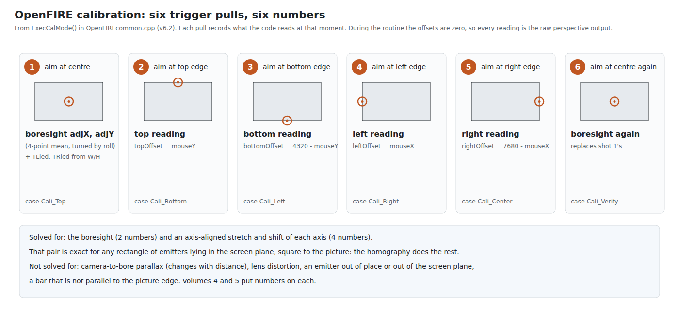
4.1 The Routine as the Code Runs It
Open-Source Firmware, Volume 5 describes calibration as a player meets it in the App and on the gun. Here is what the code records at each pull, from FW_Common::ExecCalMode() in OpenFIREcommon.cpp (v6.2).
At entry the profile’s four offsets are set to zero (lines 334–337), after backing up the old values so that cancelling can restore them (lines 324–331, 394–402). With zero offsets, the map() in GetPosition() is the identity, so during calibration mouseX and mouseY are the raw output of the homography on the 7680 × 4320 model screen. The stage counter starts at 0 and is incremented before the switch (line 414), so the first pull lands on the case named Cali_Top, and each case records what the player was aiming at for the previous prompt. The case names describe where the cursor goes next, not what was just shot.
Table 1 — 4.1 The Routine as the Code Runs It
| Pull | Player aims at | Case run | What it records |
|---|---|---|---|
| 1 | Centre of the picture | Cali_Top (lines 426–459) | Boresight adjX, adjY = the mean of the four points, rotated by the roll angle about the image centre (lines 440–443); TLled, TRled from the quad’s measured width and height (lines 445–446); the destination matrix is rebuilt (deinit(0), line 451) |
| 2 | Top edge | Cali_Bottom (line 460) | topOffset = mouseY |
| 3 | Bottom edge | Cali_Left (line 476) | bottomOffset = res_y − mouseY |
| 4 | Left edge | Cali_Right (line 492) | leftOffset = mouseX |
| 5 | Right edge | Cali_Center (line 508) | rightOffset = res_x − mouseX; the four offsets are written to the profile (lines 518–521) |
| 6 | Centre again | Cali_Verify (line 530) | Boresight recomputed exactly as in pull 1 (lines 538–541) and the matrix rebuilt; the gun enters verification mode |
A seventh pull in verification mode accepts; A or B restarts with the boresight reset to the image centre (lines 575–588); C cancels and restores the backup. Each edge pull reads one coordinate: the top and bottom shots record only Y, the left and right only X. The other coordinate of each shot is discarded.
4.2 Why Six Numbers Are Enough
The routine solves for six numbers: the boresight (two) and a stretch and shift on each axis (four). That this is enough is not obvious, and it is worth proving, because the proof shows exactly which physical assumptions the method rests on.
Let H_model be the homography the firmware computes every frame, from the camera’s quadrilateral to the model screen’s emitter rectangle, (TLled, 0)–(TRled, 4320). Let H_real be the homography from the camera to the real picture, in picture coordinates. Both are homographies from the same camera image, and they differ only in where they say the emitters are. If the real emitters form a rectangle whose sides are parallel to the picture’s edges, then the map from the model rectangle to the real rectangle is
X_real = s_x · X_model + t_x
Y_real = s_y · Y_model + t_y
an independent stretch and shift on each axis, because one axis-aligned rectangle is carried onto another by exactly that. So H_real = A · H_model with A axis-aligned, and A has four numbers. Two readings per axis — where the left and right edges of the picture fall in model coordinates, and where the top and bottom do — determine them.
Add the boresight, and the whole relationship from four image points to the barrel’s aim point on the real picture is pinned by six numbers, at any distance, angle and roll, with nothing approximate about it. The simulation confirms it: with the exact map of 4.3 and a camera on the bore, the error is zero at every position tested (aim_maths.py section 3).
The proof’s assumptions are the method’s limits:
- The emitters lie in the screen’s plane. If they stand proud of it, the homography describes their plane, not the picture’s.
- They form a rectangle, square to the picture. A bar fixed at a slight angle, or one emitter a few millimetres out of place, makes the true map from model to picture a general homography, which an axis-aligned A cannot represent.
- The boresight is a fixed image point. True for a camera tilted from the bore; false for one offset from it (Volume 5).
- The lens is a pinhole, or has been corrected to one (Volume 1).
Sections 4.8 and 4.9 put numbers on the first two; Volume 5 on the third.
4.3 The Offset Map: v6.2 Gets the Direction Wrong
The readings define where the picture’s edges fall on the model screen: the top edge at Y = T (topOffset), the bottom at Y = 4320 − B, the left at X = L, the right at X = 7680 − R. The map A must therefore carry T to 0 and 4320 − B to 4320:
Y_screen = (Y − T) · 4320 / (4320 − T − B) (exact)v6.2 instead applies (GetPosition(), lines 676–677)
mouseY = map(Y, 0, 4320, −T, 4320 + B) = −T + Y · (4320 + T + B) / 4320which stretches the range outward from the model screen’s own edges. At the top edge, where Y = T, it returns T · (T + B) / 4320, not 0. The two maps agree to first order in the offsets and differ at second order, and the error at each edge is
edge error = L · (L + R) / res (in model units, per axis)The ESP32 port found this and replaced the map. Its comment, at OpenFIREcommon.cpp lines 1338–1346 of the port, is exact: “aiming at an edge it returned offset * (offset1 + offset2) / res instead of the edge itself, an error of a few pixels on every calibrated edge (about 3-6 px with typical Square setups, up to 9-19 px).” Its MapCalibratedAxis() (lines 1168–1189) computes the exact inverse in 32-bit integers, with limits that treat an impossible calibration as none.
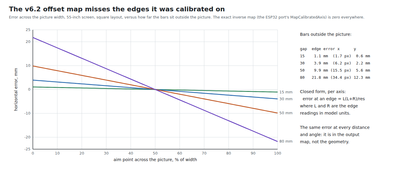
How large it is depends on how far the emitters sit outside the picture, because that sets the offsets. On a 55-inch picture with the square layout:
Table 2 — How large it is depends on how far the emitters sit outside the picture, because that sets the offsets. On a 55-inch picture with the square layout
| Bars outside the picture | Readings L = R (of 7680) | Edge error, horizontal | Edge error, vertical |
|---|---|---|---|
| 0 mm | 0 | 0 | 0 |
| 15 mm | 160 | 1.1 mm (1.7 px) | 0.6 mm |
| 30 mm | 309 | 3.9 mm (6.2 px) | 2.2 mm |
| 50 mm | 489 | 9.9 mm (15.5 px) | 5.6 mm |
| 80 mm | 727 | 21.8 mm (34.4 px) | 12.3 mm |
aim_maths.py section 2b; px are 1080p pixels on the 55-inch picture. The port’s “3–6 px typical, 9–19 px” agrees with the 30–80 mm rows.
Three properties make this error distinctive. It is the same at every distance and angle, because it lives in the output map, not the geometry; moving does not change it, and re-calibrating does not remove it. It always pulls the cursor toward the centre, so a player who aims exactly at an edge sees the cursor short of it — which matters for off-screen reloading, since the cursor must be clamped at the edge before the gun counts as off-screen (Volume 7). And it explains a piece of folk wisdom: OpenFIRE’s own guidance to put the emitters as close to the picture’s edges as possible (Open-Source Firmware, Volume 3) is, for the vertical axis, the advice that keeps this error small. With the exact map it is no longer needed for accuracy (it still helps the camera’s field of view, IR Point Tracking, Volume 4).
4.4 What TLled and TRled Are For
On the first pull, v6.2 sets the model screen’s emitter columns from the quadrilateral’s measured width W and height H, “assuming height is 100%” (line 444):
TLled = 3840 − (W · 4320 / H) / 2 TRled = 3840 + (W · 4320 / H) / 2that is, it scales the model rectangle to the same aspect ratio as the camera sees the emitters. The proof in 4.2 says any rectangle would do, since the offsets absorb the difference. The simulation agrees — and shows what the estimate is really for:
Table 3 — that is, it scales the model rectangle to the same aspect ratio as the camera sees the emitters. The proof in 4.2 says any rectangle would do, since the offsets absorb the difference. The simulation agrees — and shows what the estimate is really for
| Model columns | Offsets L, R | Worst error, exact map | Worst error, v6.2 map |
|---|---|---|---|
| From W/H at calibration (1721, 5959) | 309, 309 | 0 | 4.1 mm |
| v6.2’s uncalibrated defaults (2000, 5680) | 773, 773 | 0 | 22.3 mm |
| Deliberately wrong (1000, 6680) | −893, −893 | 0 | 29.7 mm |
aim_maths.py section 15, 55-inch, bars 30 mm out, Wii-class camera, results identical at 2.5 m head-on and at 1.8 m from 30°.
With the exact map, TLled and TRled do nothing. With v6.2’s map they keep the horizontal offsets small, and so keep the second-order error small. The aspect estimate is a workaround for the map, whether or not it was written as one. A fork that adopts the exact map can keep it (it costs nothing) or drop it; either way the result is the same.
4.5 The Boresight Shot: a Mean Is Not a Centre
The boresight should be the image position of the point the barrel aims at during the centre shot, the picture’s centre. v6.2 uses the mean of the four emitter images (testMedianX(), testMedianY()). Seen head-on, the two coincide for a symmetric layout. Seen from an angle, they do not: perspective compresses the far side of the emitter rectangle, and the mean of four projected corners is not the projection of the rectangle’s centre.
The simulation calibrates from several angles and then tests both where the player calibrated and after he moves to stand head-on:
Table 4 — The simulation calibrates from several angles and then tests both where the player calibrated and after he moves to stand head-on
| Calibrated from | Mean-to-centre gap in the image | Worst error where calibrated | Worst error after moving head-on |
|---|---|---|---|
| Head-on | 0 | 0 | 0 |
| 20° to the side | 23 arcmin | 1.1 mm | 4.1 mm |
| 30° | 31 arcmin | 1.6 mm | 9.8 mm |
| 40° | 36 arcmin | 2.0 mm | 18.5 mm |
aim_maths.py section 4; 55-inch, 2.5 m, Wii-class.
The error is small where the player calibrated, because the four edge shots partly absorb it there, and grows when he moves. A player who calibrates from the sofa at an angle and later plays standing in front of the screen carries a boresight error into every shot.
There is an exact fix, and it is one line. The centre of a rectangle is where its diagonals cross, and a homography carries straight lines to straight lines, so the image of the emitter rectangle’s centre is the intersection of the image quadrilateral’s diagonals, from any viewpoint. If the emitter rectangle is centred on the picture — the square layout’s bars are, when mounted symmetrically — that point is the image of the picture’s centre. Replacing the mean with the diagonal intersection, the simulation’s errors in the table above all fall to zero (section 19). The cost is one 2 × 2 solve on one frame per calibration.
4.6 The Boresight Shot: Rotated by the Roll
Lines 440–443 do not store the mean as it is. They rotate it about the image centre (512 × 4, 384 × 4) by OpenFIREsquare.Ang(), the mean angle of the quadrilateral’s top and bottom edges at that moment:
adjX = (mX − 2048)·cos(ang) − (mY − 1536)·sin(ang) + 2048
adjY = (mX − 2048)·sin(ang) + (mY − 1536)·cos(ang) + 1536
This is the roll correction of Samco 2IR (Volume 2, 2.3) carried into a place where it no longer belongs. In the similarity method, the measured point was rotated back every frame to undo the gun’s cant. In the homography method, the four points are never rotated; the homography itself handles roll exactly. The boresight is a fixed point in the camera’s image — where the aim point appears — and it does not move when the gun cants. Rotating it by the cant at the moment of calibration moves it away from where it belongs, by an amount proportional to that cant and to the boresight’s distance from the image centre.
If the gun is held level at calibration, ang ≈ 0 and nothing happens. If the camera sits on the bore, the boresight is at the centre and the rotation moves nothing. The error appears when both conditions fail — a camera tilted a little from the bore, and a gun canted a little during calibration. With the camera pitched 2° from the bore:
Table 5 — If the gun is held level at calibration, ang ≈ 0 and nothing happens. If the camera sits on the bore, the boresight is at the centre and the rotation moves nothing. The error appears when both conditions fail — a camera tilted a little from the bore, and a gun canted a little during calibration. With the camera pitched 2° from the bore
| Cant held during calibration | Worst error playing level, v6.2 | Without the rotation |
|---|---|---|
| 0° | 0 | 0 |
| 5° | 1.0 mm | 0.2 mm |
| 10° | 3.2 mm | 0.4 mm |
| 20° | 11.6 mm | 0.7 mm |
aim_maths.py section 6; 55-inch, 2.5 m, Wii-class. The residual without the rotation is the mean-versus-centre effect of 4.5, which the diagonal fix also removes.
The proposal for the fork is to delete the rotation, storing the diagonal intersection as it is. The calibration-shots figure records the rotation as v6.2 has it.
4.7 One Frame per Shot
Each pull records the reading from one camera frame: whatever GetPosition() last produced. That frame carries the centroid noise of all four points. For the Wii-class camera at 2.5 m, with an assumed 0.1-physical-pixel noise per point (a figure IR Point Tracking, Volume 6 sets out to measure), the boresight from one frame has a standard deviation of 0.56 mm on the screen. Averaged over 70 frames, a third of a second at 209 Hz, it falls to 0.07 mm (aim_maths.py section 20).
Prow Enhanced did exactly that average for its centre shot (CalCenter(), SamcoEnhanced.ino lines 993–1034: “accumulate center position over a bit of time for some averaging”, up to 333 ms while the trigger is held). OpenFIRE dropped it. The camera noise is not the main reason to restore it: a hand-held gun also wanders, and the trigger pull itself jerks it. An average over a held trigger, taken from a frame or two after the pull begins, averages out tremor and avoids recording the moment of the jerk. The same applies to every edge shot.
4.8 What Calibration Cannot Absorb
The proof in 4.2 assumed a rectangle of emitters, square to the picture, in its plane. Break those assumptions and the simulation shows what is left (calibrated at 2.5 m head-on with the exact map and the diagonal boresight, then tested):
Table 6 — The proof in 4.2 assumed a rectangle of emitters, square to the picture, in its plane. Break those assumptions and the simulation shows what is left (calibrated at 2.5 m head-on with the exact map and the diagonal boresight, then tested)
| Emitter fault | Where calibrated | 1.5 m | 3.5 m | 2.5 m, 30° aside | 2.0 m, 40° the other side |
|---|---|---|---|---|---|
| None | 0 | 0 | 0 | 0 | 0 |
| Top-right emitter 10 mm too far right | 5.2 mm | 6.1 | 6.1 | 5.4 | 6.3 |
| Top-right emitter 10 mm too high | 7.1 mm | 7.8 | 8.0 | 7.3 | 7.0 |
| Top bar rotated 1° | 9.0 mm | 9.0 | 9.0 | 9.0 | 9.0 |
| Top bar 15 mm proud of the screen | 1.4 mm | 3.6 | 1.6 | 9.8 | 14.8 |
| All four emitters 40 mm proud | 0 | 6.8 | 2.9 | 24.9 | 39.9 |
aim_maths.py section 16; 55-inch, Wii-class.
Two kinds of error appear. A misplaced or tilted emitter produces an error that is about the same everywhere — a fixed distortion of the mapping — of the order of the misplacement itself or larger: a 1° tilt of a 730 mm bar moves each end by about 6 mm, and the aim error is 9 mm. An emitter out of the screen plane produces an error that is zero where the player calibrated and grows with the angle from which he sees the screen, as the parallax between the two planes opens up: 40 mm of standoff costs 40 mm from 40° to the side. The practical rules follow: mount the bars level and symmetric to a millimetre or two, using the App’s alignment assistant (Open-Source Firmware, Volume 5), and as close to the screen’s surface as the bezel allows.
4.9 A Four-Corner Calibration
The axis-aligned map A has four numbers because v6.2 reads one coordinate per edge shot. If instead the player shoots the four corners of the picture (or four points inset from them) and both coordinates of each are kept, there are eight readings: enough to fit a full homography from the model screen to the picture in place of A. That map absorbs a misplaced or tilted emitter in the screen plane completely, at the calibration position, because the true model-to-picture map is then a homography.
Table 7 — 4.9 A Four-Corner Calibration
| Emitter fault, four-corner calibration | Where calibrated | 1.5 m | 3.5 m | 30° aside | 40° the other side |
|---|---|---|---|---|---|
| Top-right emitter 10 mm too far right | 0.1 mm | 1.5 | 1.4 | 1.1 | 1.3 |
| Top-right emitter 10 mm too high | 0.1 mm | 1.5 | 1.4 | 1.1 | 1.3 |
| Top bar 15 mm proud | 0 | 2.3 | 1.0 | 8.4 | 13.5 |
| All four 40 mm proud | 0 | 6.8 | 2.9 | 24.9 | 39.9 |
aim_maths.py section 22; corner targets inset 5 % from the picture’s corners.
A misplaced emitter drops from 5–8 mm to about 1.5 mm. What remains is the boresight: with an asymmetric emitter quadrilateral, the diagonals no longer cross at the image of the picture’s centre, the boresight is slightly wrong, and a boresight error is an angle, which grows with distance away from where it was calibrated. Out-of-plane emitters are not helped at all; that error is parallax, and no single-position calibration can remove it. The cost is four corner shots in place of the four edge shots, with a computation that already exists in the firmware (computeSquareToQuad), and a change to the App’s calibration screen. It is a proposal for Our Firmware, not a necessity: a correctly mounted bar does not need it.
4.10 Samco, Prow and GUN4IR
Table 8 — 4.10 Samco, Prow and GUN4IR
| Firmware | Shots | Unknowns | What it solves for |
|---|---|---|---|
| Samco 2IR | 2: near top-left, near bottom-right (Samco_2.0_2IR.ino lines 142–168) | 4 | Offset and gain per axis of a linear map from the de-rolled bar midpoint (Volume 2, 2.2) |
| Prow Enhanced / Samco 4IR | Centre held 1/3 s; then vertical and horizontal range trimmed by eye with A/B (SamcoEnhanced.ino lines 36–55, 993–1100) | 4 | Centre (2) and the two scale factors that relate the quadrilateral’s height to the screen range (Volume 2, 2.5) |
| OpenFIRE v6.2 | 6 (4.1) | 6 | Boresight (2), axis-aligned stretch and shift (4) |
| GUN4IR | ”five-step calibration of camera offset and LED placement” (user guide v1.2, as summarised in Open-Source Firmware, Volume 1) | not known | Closed source |
Only OpenFIRE’s routine solves for a model that is exact under its assumptions. Samco 2IR’s and Prow’s solve exactly for models that are not (Volume 2).
4.11 Why This, and Why Not the Others
Proposed, for Our Firmware: keep OpenFIRE’s six-shot routine and its App screens, with four changes, in order of value:
- The exact offset map (the ESP32 port’s
MapCalibratedAxis()): removes 4 mm at 30 mm bar gaps and 22 mm at 80 mm, pose-independent (4.3). - The boresight as the diagonal intersection, not rotated: removes 4–19 mm for a player who calibrated at an angle and then moved, and up to 12 mm for a canted calibration with a tilted camera (4.5, 4.6).
- Average each shot over the held trigger, skipping the first frames after the pull: removes calibration noise and the trigger jerk (4.7).
- Optionally, a four-corner mode that fits a full homography: absorbs emitter misplacement (4.9).
Table 9 — 4.11 Why This, and Why Not the Others
| Option | Why not, or why |
|---|---|
| Keep v6.2’s routine unchanged | Leaves the three errors above; each is a few lines to fix and the ESP32 port has already fixed one |
| Adopt the ESP32 port’s calibration wholesale | It fixes the map but keeps the mean and the rotation (port lines 707–716 and 805–814 match v6.2’s); its other changes come with its own camera code (decision row P-RE18 is still open) |
| Four-corner calibration as the default | Its benefit is for badly mounted bars; a well-mounted bar does not need it, and corners near the bezel are harder to hit than edge midpoints |
| Nine-point least-squares calibration | Would also average noise and absorb a little lens error, but nine shots is a chore at every profile change, and the averaging of item 3 does most of the same work |
| Prow-style trim by eye | Only made sense for a model with free scale factors; the homography has none to trim |
4.12 What Could Not Be Verified
- Every error figure is from the simulation with an ideal camera; none is a bench measurement.
- Whether the rotation of the boresight was meant to compensate for something the simulation does not model. No comment in the source explains it, and it predates OpenFIRE: the same expression rotates the output position every frame in Prow (
SamcoPositionEnhanced.cpplines 233–237), where it belonged. - GUN4IR’s calibration mathematics.
Sources
- TeamOpenFIRE,
OpenFIRE-Firmwareat8b651a25(v6.2):OpenFIREmain/OpenFIREcommon.cpp(ExecCalMode, GetPosition),OpenFIREmain/OpenFIREconstant.h(calibration stage enum, lines 73–79),libraries/OpenFIREPosition/OpenFIRE_Square.cpp— read 2026-10-19. - Alessandro Satanassi,
OpenFIRE-Firmware-ESP32atf6458fc9:lightgun/src/OpenFIREcommon.cpp(MapCalibratedAxis and its comment) — read 2026-10-19. - Mike Lynch,
ir-light-gun(Prow Enhanced) ataeab7d1c:SamcoEnhanced/SamcoEnhanced.ino,libraries/SamcoPositionEnhanced/SamcoPositionEnhanced.cpp— read 2026-10-19. - Sam Ballantyne,
IR-Light-Gun(Samco) at929490f3:Samco_2IR/Samco_2.0_2IR/Samco_2.0_2IR.ino— read 2026-10-19. - Own simulation,
04-templates/aim_maths.py, sections 2b, 3, 4, 6, 15, 16, 19, 20 and 22, run 2026-10-19.
Comments (0)