Fully Wired · Volume 1
The Fully Wired Gun — One Cable, Two Sources, One Plug
What the fully wired architecture is, why the first printed MP7 uses it, what has to cross the cable, how the commercial guns already do it, and the order in which the plugs go in
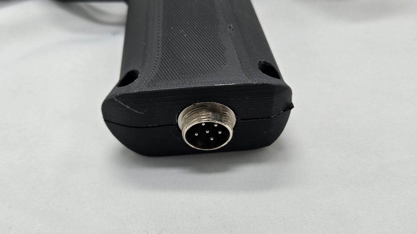
A recoil light gun needs two things from outside itself: a data link to whatever runs the game, and enough power to throw a solenoid’s plunger several times a second. The fully wired gun takes both down one cable. It is the oldest and plainest way to build a recoil gun, and it is the architecture the first build in this category uses. This dive treats it as a complete system, from the wall outlet and the PC’s USB port to the pins inside the gun’s magazine, and puts numbers on every part of the path.
1.1 What “Fully Wired” Means
In this category, “fully wired” means both the data and the recoil power arrive on a cable. Nothing in the gun stores energy beyond the local reservoir capacitor on the carrier board, and nothing in it talks by radio.
Concretely, for the printed MP7 (decision D35) it means:
- Data and logic power over USB 2.0 full speed. The Raspberry Pi Pico enumerates as OpenFIRE’s composite device (mouse, keyboard, gamepad and a serial port for feedback commands) and runs from the port’s 5 V (Open-Source Firmware, Power Supplies Vol 1).
- Recoil power from a 24 V wall brick. The rail is 24 V class, 18 to 28 V working (D14); the stages are regulated-current DRV8251A drivers (D13), fired one at a time (D16) so that a 2.5 A brick of the GST60A24 class is enough (Power Supplies Vol 2).
- One connector at the gun. A single locking GX (aviation) connector in the magazine base plate carries USB and the 24 V rail together, with no barrel jack beside it (D31). The brick’s own 5.5 × 2.1 mm plug and the PC’s USB-A plug meet the cable at its far end.
- The foot pedal on the same cable, if the pin count allows: proposed row CI-7 puts the pedal’s 3.5 mm jack at the far end of the cable and carries its two switch lines up to the gun on spare conductors (Controls and Inputs Vol 6). This dive allocates those pins.
Everything in this dive follows from those four lines.
1.2 Three Architectures, Three Dives
The Power and Connectivity sub-category splits the question “how do power and data get into the gun” three ways, one dive each:
Table 1 — The Power and Connectivity sub-category splits the question "how do power and data get into the gun" three ways, one dive each
| Architecture | Data | Recoil power | Cable to the gun | Dive |
|---|---|---|---|---|
| Fully wired | USB cable | 24 V brick, down the same cable | One umbilical, one GX plug | This dive |
| Wireless power only | USB cable | Battery pack in the gun | A USB cable only | Wireless Power Only |
| Fully wireless | Radio to a dongle (the ESP32-S3 trial, D25 and D30; Nordic boards on hand, D38) | Battery pack in the gun | None in play; a charging lead | Fully Wireless |
The battery that the other two architectures depend on is the subject of LiPo Batteries, and a single USB-C cable carrying both data and a negotiated 20 V or 28 V contract is a variant of this architecture treated in USB-C Power Delivery. This dive deals only with the two-source cable: a USB link from the PC and a separate DC pair from a brick, sharing a sleeve and a plug.
1.3 Why the First Build Is Wired
Five owner decisions point the same way.
- D17: no USB-only prototype. USB alone cannot sustain full-strength autofire (Power Supplies Vol 3), so the gun goes straight to a 24 V brick. A brick needs a cable; once there is a cable for power, carrying USB beside it costs nothing.
- D35: start with a 3D-printed MP7 to get a working model. The quickest route to a gun that shoots is the one with the fewest new subsystems. The wired gun adds no battery, no charger, no protector and no radio, each of which has its own dive and its own bench programme.
- D14 and D16: a 24 V rail, one stage at a time. These were chosen with a brick in mind: the stage is sized to sit below the brick’s over-current trip band. The same rail can later come from a 6S pack (LiPo Batteries Vol 2), so nothing in the wired gun is thrown away when a battery arrives.
- D31: one GX connector at the base plate. The connector decision presumes a cable that carries both USB and the rail.
- D6 and P-PB-9: the cable leaves through the magazine. The printed magazine is designed as the cable’s exit and strain relief (MP7 Printed Build Vol 5).
There are engineering reasons too. A cable has the lowest latency of any link (the wire itself adds about 15 ns over 3 m; Vol 5), it cannot run flat in the middle of a game, and a brick is the only source here that has a current limit built in: a fault that leaves a coil on is limited by the brick’s hiccup protection, where a battery would deliver well over a hundred amps into the same fault (LiPo Batteries Vol 4). Its costs are a cable to trip over and a plug to wear, and Vol 6 prices both.
1.4 The System, Block by Block
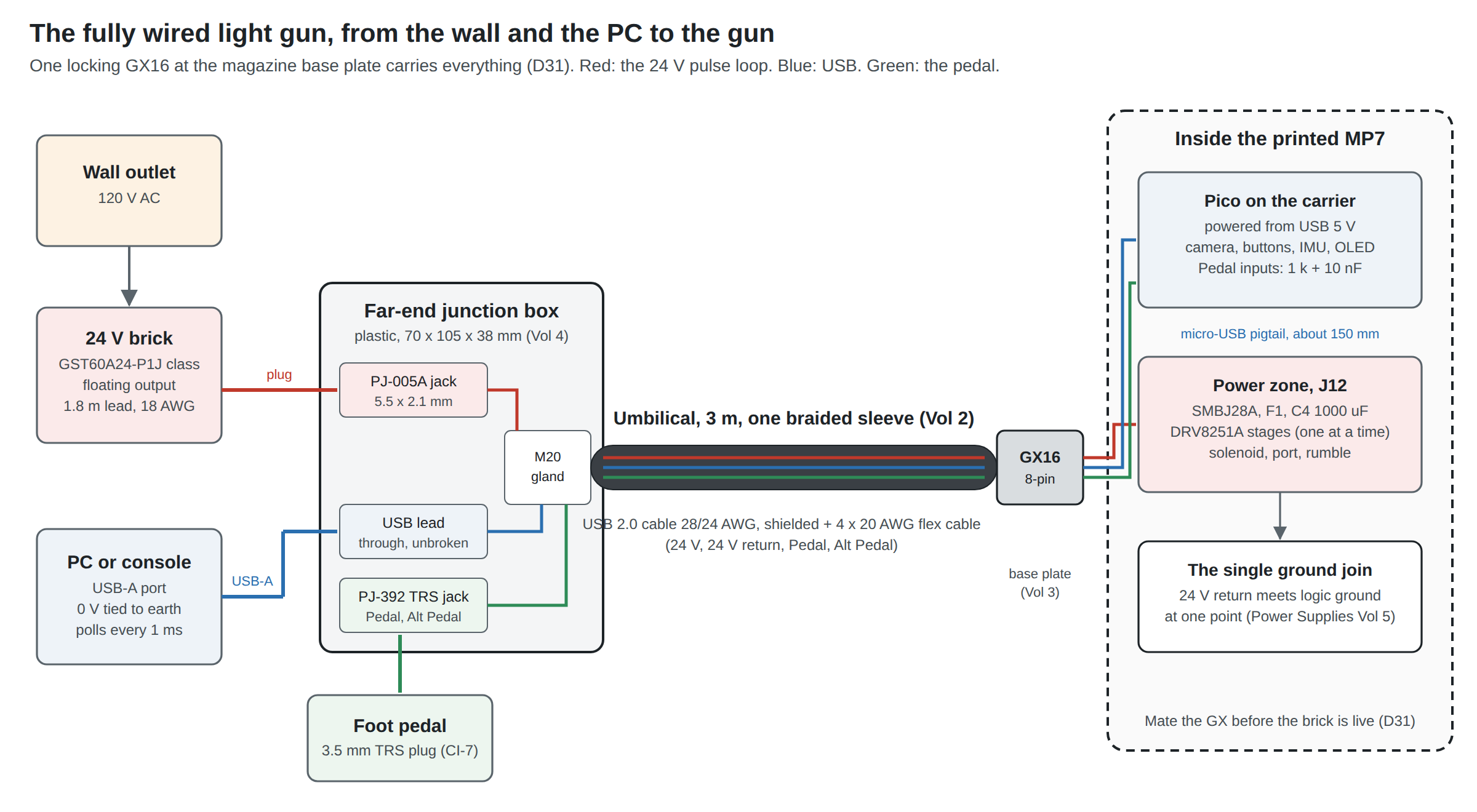
Reading the diagram from left to right:
- The brick. A Mean Well GST60A24-P1J class unit: 24 V, 2.5 A, a floating (unearthed) output, a 1.8 m lead of 18 AWG ending in a 5.5 × 2.1 mm plug. Its selection, its trip band and why it is floating belong to Power Supplies Vol 2 and are not repeated here.
- The PC or console. Any USB host. Its 0 V is almost always tied to mains earth through its own supply. It polls the gun’s interrupt endpoint every millisecond.
- The far-end junction box (Vol 4). A small plastic box that takes the brick’s plug in a panel jack and the pedal’s 3.5 mm plug in a panel jack, lets the USB cable pass straight through unbroken to its USB-A plug, and clamps the umbilical in a gland. It contains no electronics, deliberately.
- The umbilical (Vol 2). Three metres of braided sleeve over two cables: a real USB 2.0 cable (a 90 Ω shielded twisted pair for data, 24 AWG for VBUS and ground) and a four-conductor 20 AWG flexible cable for the 24 V pair and the two pedal lines.
- The GX16 (Vol 3). An eight-pin aviation connector, sockets on the cable and pins in the base plate, with the 24 V on the centre pin so that no rotational slip during mating can move it onto another contact.
- Inside the gun. A short micro-USB pigtail to the Pico’s own connector (Stage 1 of the Reference Electronics carrier keeps USB off the board), the 24 V pair to J12 and its fuse, TVS and 1000 µF reservoir, and the pedal lines to two button inputs with the 1 kΩ and 10 nF network fitted. The 24 V return and the logic ground meet at one point (D34 and Power Supplies Vol 5).
1.5 What Has to Cross the Cable
Eight conductors, not counting the USB cable’s shield:
Table 2 — Eight conductors, not counting the USB cable's shield
| Signal | From | Normal level | Current | Character |
|---|---|---|---|---|
| VBUS | PC | 4.75 to 5.25 V at a high-power port | about 150 mA estimated for Pico, camera and LEDs (Power Supplies Vol 1); 500 mA is the configured limit | Steady |
| USB GND | PC | 0 V | the same | The reference for D+ and D− |
| D+ | both | 0 to 3.3 V, differential | 12 Mbit/s, 4 to 20 ns edges | |
| D− | both | 0 to 3.3 V, differential | as D+ | |
| +24 V | brick | 24 V class, 18 to 28 V window (D14) | up to about 2.4 A while a regulated stage ramps; rumble about 0.09 A | Pulsed, a few tens of milliseconds at a time |
| 24 V return | gun | 0 V of the brick | the same | Must not share a conductor with USB GND |
| Pedal | pedal switch | pulled up to 3.3 V in the gun | under 1 mA | A contact closure to ground |
| Alt Pedal | pedal switch | the same | the same | the same |
Two facts in that table drive most of the design. The 24 V conductor carries amps in pulses, and its return must come back on its own conductor; if it shares the USB ground, every shot shifts the gun’s ground against the PC’s, which is the commonest cause of a gun that disconnects when it fires (Power Supplies Vol 5). And the data pair is a transmission line at 3 m, so it must be a real USB pair, not any two wires in a multicore (Vol 5).
The pedal’s ground is the gun’s logic ground, carried on the USB GND conductor. Its current is a fraction of a milliamp and adds nothing measurable to the USB ground drop.
1.6 How the Commercial and Kit Guns Do It
Every recoil gun on sale that is not battery-powered is some version of this architecture. Three are instructive because each makes a different choice about where the two sources join.
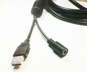
Ultimarc AimTrak with recoil. Ultimarc’s page says simply that “The recoil power is routed via the connecting cable”, which is a 4 m USB cable; the recoil supply is 24 to 36 V, centre-positive on a 5.5 × 2.1 mm plug, and buyers are told “DO NOT use a supply with a current capability of greater than 4 amps”, because the brick’s current limit is part of the design.1 The gun with recoil is $120.00 and without it $95.00 (Ultimarc, 2026-10-19). The join is a moulded split near the far end of one cable, with the power socket in-line rather than in a box.
GUN4IR GC45, UK and EU set. The pre-modded set ships “3m USB and power cables, tied together in a nice sleeve”, with “1x USB to 5v power connector and power switch”, and states that the solenoid’s 12 V supply is not included.2 That is two separate cables in one sleeve, the arrangement this dive also chooses, at 12 V rather than 24 V. The set was listed at €250,00 and sold out on 2026-10-19.
Blamcon. Gaming Nexus’s review of the Blamcon printed guns notes that “all of the Blamcon guns … use the GX16 connector on the gun. This connector leads to a cable that splits into the USB and power wire to power the solenoid”, and that the reviewer found “the wires to the GX16 connector” among the hardest joints to solder.3 It is the nearest published precedent for D31: a printed gun, a GX16 in the base of the grip, and one cable that splits at the far end.
None of the three publishes its pin allocation, its conductor gauges or its grounding, which is the gap the rest of this dive fills.
1.7 The Order the Plugs Go In
D31 accepts that a GX connector is not made for mating live, and fixes the order instead. The rule, with the reason for each step:
Table 3 — D31 accepts that a GX connector is not made for mating live, and fixes the order instead. The rule, with the reason for each step
| Step | Action | Why in this order |
|---|---|---|
| 1 | Mate the GX at the gun and tighten the ring. The brick is unplugged at the box; USB may be live. | The GX is the only contact without a make-last design. With the brick out, the only live source during mating is the PC’s current-limited VBUS, and the pin map (Vol 3) puts VBUS between the two pedal pins, so a slip can push no more than a few milliamps through a pedal input’s 1 kΩ. |
| 2 | Plug the USB-A into the PC, if it is not already in. | USB is designed for live insertion; its plug makes ground and VBUS before data. |
| 3 | Plug the brick’s barrel into the junction box with the brick unpowered. | The gun’s 1000 µF reservoir charges through the brick’s soft start, not through a spark at the jack. |
| 4 | Plug the brick into the wall. | |
| To unplug | Reverse: brick out of the wall, then the GX. | The reservoir discharges through the stages’ quiescent current; the gun’s GX pins carry no hazard once the brick is off. |
Step 3 is the one most likely to be skipped. Its cost is a small spark and contact erosion at the jack every time the brick’s barrel goes in live, and the larger concern of a voltage overshoot when a live source is switched into a cable with a capacitor at the end (Vol 4, 4.6). A labelled box with the order printed on its lid is the practical fix.
1.8 What This Dive Covers, and What It Leaves to Others
Table 4 — 1.8 What This Dive Covers, and What It Leaves to Others
| Question | Where it is answered |
|---|---|
| The whole wired system as a block diagram, and why it comes first | This volume |
| The umbilical: conductors, gauges, voltage drop, shielding, sleeve, flex life, strain relief | Vol 2 |
| The GX16: ratings, the pin map, slips, wiring the gun side | Vol 3 |
| The far-end junction box: circuit, parts, prices, build | Vol 4 |
| USB signal integrity through a non-impedance-controlled connector, latency, grounding in the cable | Vol 5 |
| What fails, what it all costs, bench checks and the decisions to log | Vol 6 |
| Bricks, trip bands, the barrel jack’s history, cable drop in general, the input TVS | Power Supplies |
| The ground join and diagnosing disconnects | Power Supplies Vol 5 |
| The carrier board, J12, the stages, the camera | Reference Electronics |
| The pedal, its jack wiring and its input filter | Controls and Inputs Vols 5–6 |
| The magazine as the cable’s exit, its clamp and service connector | MP7 Printed Build Vol 5 |
| The full latency chain from camera to screen | Aiming Maths and Calibration Vol 7 |
| Firmware changes (none are needed for this architecture) | Our Firmware |
1.9 Why This, and Why Not the Others
Criteria for the first build’s architecture: fewest new subsystems between the parts on hand and a gun that shoots (D35); full-strength autofire (D17); the 24 V rail and one-stage rule (D14, D16); a current-limited source while the firmware and stages are unproven; latency; cost.
Table 5 — 1.9 Why This, and Why Not the Others
| Candidate | Verdict | Reason |
|---|---|---|
| Fully wired: USB plus a 24 V brick on one umbilical and one GX plug | Pick for the first build | Adds only a cable, a connector and a passive box. The brick’s current limit backs up an unproven stage. Lowest latency and no runtime limit. Its costs, a tether and a plug that wears, are known and cheap to manage. |
| Two separate cables, USB and a barrel-jack lead | Rejected | Two holes in the base plate, two leads to snag, and a barrel jack that does not lock (the PS-4 option D31 withdrew at the gun). |
| USB only, recoil from VBUS through storage | Rejected (D17) | Fades to a tap within a burst from any USB-A port (Power Supplies Vol 3). |
| One USB-C cable with Power Delivery at 20 V or 28 V | Not first | Removes the brick and the box, but adds a PD sink, a charger able to deliver 20 V at 3 A, and a host or adapter that can do it; its own dive, USB-C Power Delivery, weighs it. |
| Wireless power only: USB cable plus a pack in the gun | Second | Keeps the cable and adds the pack, protector and charger. Worth it only if the brick lead is the part players object to (Wireless Power Only). |
| Fully wireless | Later | Needs both the pack and a radio link the D25 trial has not yet tested (Fully Wireless). |
Footnotes
-
Ultimarc, “AimTrak Light Gun With Recoil” (C-ATE0BK and colours), product page: “The recoil power is routed via the connecting cable”; “4 Meter USB Cable”; “The required voltage is 24-36 Volts”; “DO NOT use a supply with a current capability of greater than 4 amps”; $120.00. Photo
images/1/recoilpower1.jpgfrom the same page. https://www.ultimarc.com/light-guns/aimtrak-light-gun/aimtrak-light-gun-with-recoil/ (read 2026-10-19). ↩ -
GUN4IR, “UK and EU Exclusive - GUN4IR® GC45 Pre-Modded lightgun set”: “3m USB and power cables, tied together in a nice sleeve”; “1x USB to 5v power connector and power switch”; €250,00, sold out. https://www.gun4ir.com/products/uk-exclusive-gun4ir®-gc45-pre-modded-lightgun-set (read 2026-10-19). ↩
-
John Yan, “Blamcon Light Guns”, Gaming Nexus, 1 October 2025, text and photo 10. https://www.gamingnexus.com/Article/16263/Blamcon-Light-Guns/ (read 2026-10-19). ↩
Comments (0)