Fully Wired · Volume 3
The GX16 — Ratings, the Pin Map, and a Slip That Cannot Put 24 V on USB
What a GX16 aviation connector is and what its sellers' ratings are worth, why it needs eight pins, the pin allocation that puts 24 V where no slip can move it and VBUS where a slip does no harm, and how the gun side is wired
D31 settled the connector family: one GX at the magazine base plate for everything, mated with the brick unplugged, “and the pins are allocated so a one-position slip cannot put 24 V on a USB or logic pin.” This volume does the allocation. Power Supplies Vol 2 owns the history of the connector choice, the barrel jack it replaced and why; that is not repeated.
3.1 What a GX16 Is
“GX16” names a pattern, not a product. It is a circular metal connector with an M16 × 1 coupling thread, made by many factories to broadly the same dimensions, sold in pairs: a panel part with a nut and a cable part with a knurled coupling ring and a screw clamp. Contacts are solder-cup, the insert is keyed, and the pin counts sold run from two to around ten.
Olimex publishes a dimension drawing for its four-pin GX16 that stands in for the family: M16 × 1 thread, an 18.8 mm hex panel nut, a cable clamp 10.0 mm across, and 45.7 mm long mated.1 A panel part therefore needs a 16 mm hole (or the anti-rotation shape of the part bought) and a boss wider than the nut’s 18.8 mm with room for a wrench. Whether that fits the base plate is the measurement MP7 Printed Build is waiting on (MP7 Printed Build Vol 5, 5.6).
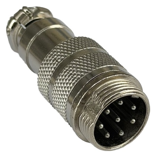
The eight-pin insert is the one that matters here: seven contacts on a circle and one on the axis, as Tayda’s photograph shows. That geometry is what the pin map in 3.5 exploits.
3.2 What the Ratings Are Worth
Table 1 — 3.2 What the Ratings Are Worth
| Source | Part | Current | Voltage | Other |
|---|---|---|---|---|
| Tayda (A-8801, $1.09, 2026-10-19)2 | GX16, 8-pin | ”5A @250V” | ||
| Olimex (€1.55 a pair, 2026-10-19)1 | GX16, 4-pin | ”20 A / 220 V” | 1000 V AC withstand | contact resistance 20 mΩ |
| Olimex3 | GX12, 4-pin | 5 A | 250 V AC / 300 V DC | (the figure Power Supplies Vol 2 quotes) |
| binder, 723 series (RS listing)4 | M16, 8-pin, maker part 09-0174-00-08 | 5 A per contact | 60 V | IP67, more than 500 mating cycles |
Two lessons. Seller figures for nominally the same GX16 differ by a factor of four, and Olimex’s 20 A for a four-pin part sits beside its own 5 A for the smaller GX12 with no test conditions for either. And the one maker-backed figure for this size, binder’s for a properly specified M16 eight-pin connector, is 5 A per contact, 60 V and more than 500 matings.
What the gun needs is modest against any of them: about 2.4 A on two contacts while a stage ramps, a few hundred milliamps on VBUS and ground, and microamps on the rest. Current is not the GX16’s problem. Its unknowns are contact resistance at eight pins, plating, and how many matings it survives, and those are bench checks (Vol 6, W2 and W3). Power Supplies’ open question, “GX16 current rating still from sellers only”, is answered in this sense: no maker datasheet for a GX16 was found, and the design does not need one, because it runs every contact at under half the lowest figure any seller gives.
3.3 Why Eight Pins
The cable carries eight conductors (Vol 1, 1.5): VBUS, USB ground, D+, D−, +24 V, 24 V return, Pedal and Alt Pedal. Each needs its own contact:
- The 24 V return cannot share a contact with USB ground. Sharing puts the pulse current through the USB ground path, the fault Power Supplies Vol 5 traces most disconnects to. The two grounds meet once, inside the gun, at the single join.
- The pedal lines need no ground of their own. Their switch returns through the pedal plug’s sleeve, which the junction box ties to USB ground (Vol 4); a fraction of a milliamp adds nothing to that conductor’s drop.
- The USB shield gets no pin. It is terminated at the PC end only (Vol 5, 5.6).
Six or seven pins would mean dropping the pedal from the cable (the fallback in Controls and Inputs Vol 6, a jack on the gun) or doubling up returns, which is the one thing not to do. More than eight would give a spare and a shield pin, but the larger pin counts in a 16 mm shell crowd the contacts, and nothing needs the spare. Eight is the count.
3.4 How a Slip Happens
A keyed connector cannot mate at the wrong angle once the key is in its slot. The risk D31 names is the moment before: the plug is offered up, turned to find the key, and pressed, and if the contacts reach their sockets before the key reaches its slot, pins can touch neighbouring sockets for a moment. Power Supplies Vol 2 describes it as pins touching “the wrong sockets briefly” while the coupling ring is turned.
Whether this can happen at all depends on two lengths the sellers do not publish: how far the key projects ahead of the pin tips, and how far the pins sit back inside the shell. If the key engages before any pin touches a socket, a slip is impossible; if not, the worst plausible error is a rotation of one position, since a larger rotation leaves the key visibly out of line. Both lengths can be measured with calipers on the part in hand (bench check W2). The pin map assumes the worse case.
A rotation moves every contact on the circle to its neighbour, one way or the other, and leaves the centre contact where it is. A tilt large enough to bring the centre pin across to a socket on the circle (several millimetres) cannot happen inside a 16 mm shell that guides the plug.
3.5 The Pin Map
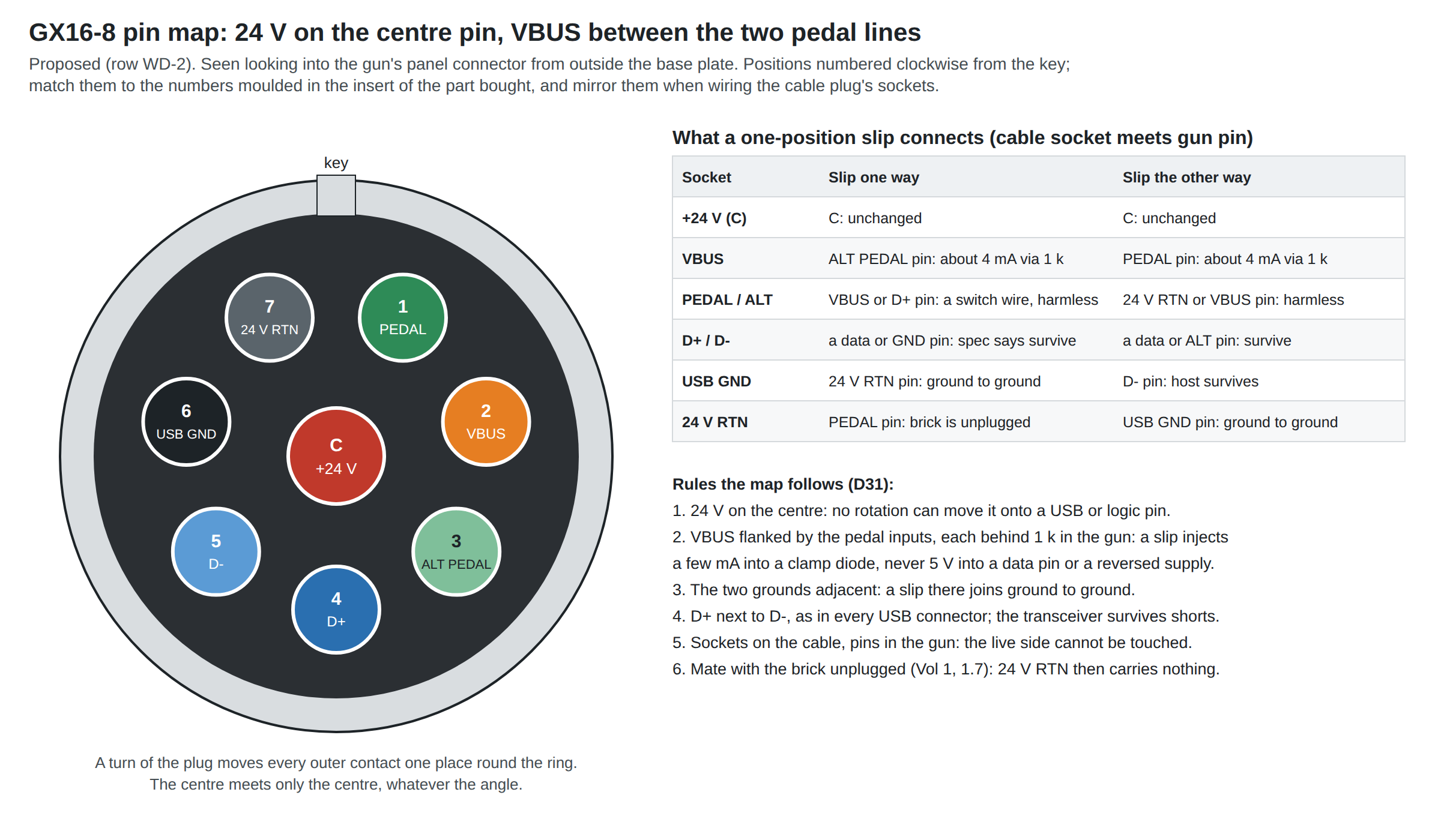
Table 2 — 3.5 The Pin Map
| Position | Signal | Wire colour suggested | Neighbours on the circle |
|---|---|---|---|
| Centre | +24 V | red, 20 AWG (85004 core 1) | none: it has no neighbours that a rotation can bring |
| 1 | Pedal | green | 7 (24 V return), 2 (VBUS) |
| 2 | VBUS | USB red | 1 (Pedal), 3 (Alt Pedal) |
| 3 | Alt Pedal | green/white | 2 (VBUS), 4 (D+) |
| 4 | D+ | USB green | 3, 5 |
| 5 | D− | USB white | 4, 6 (USB ground) |
| 6 | USB ground | USB black | 5, 7 |
| 7 | 24 V return | black or grey, 20 AWG | 6 (USB ground), 1 (Pedal) |
The reasoning, rule by rule:
- 24 V on the centre. This is the whole of D31’s requirement in one placement. No rotation moves the centre contact, so no slip, in either direction, by any number of positions, can put 24 V on a USB or logic pin.
- VBUS between the two pedal inputs. VBUS is the only other source that may be live while the GX is mated (the PC stays on; Vol 1, 1.7). If it slips, it lands on a pedal pin, which in the gun reaches the Pico only through the 1 kΩ of the input network (Controls and Inputs Vol 5, 5.7). The worst case is 5 V through 1 kΩ into a clamp diode of an unpowered Pico: about 4 mA. The alternatives are worse. Next to USB ground, a slip would put host VBUS on the gun’s ground while a gun data pin sat on host ground, driving current through the RP2040’s protection diodes limited only by the USB line’s series resistor, tens of times more. Next to D+ or D−, it would put 5 V on a data pin of an unpowered Pico.
- The two grounds side by side. A slip between positions 6 and 7 joins ground to ground, which is what the gun’s single join does anyway.
- D+ beside D−. As in every USB connector. A slip swaps or grounds them, and the USB specification requires a transceiver to “withstand a continuous short circuit of D+ and/or D- to VBUS, GND, other data line, or the cable shield at the connector, for a minimum of 24 hours without degradation”.5
- What a slip does to the gun. In every one-position slip, the gun’s own VBUS pin meets a pedal or Alt Pedal socket, so the Pico is simply unpowered. Nothing enumerates; the user sees a dead gun, turns the plug until the key drops in, and tightens the ring.
With the brick unplugged during mating, as the procedure requires, the 24 V return carries nothing, and its landing on the Pedal pin in one direction is harmless. If the procedure were ignored and the brick were live, that slip would let the gun’s reservoir charge through a pedal input’s 1 kΩ, about 24 mA decaying over a second, into a clamp diode. That is the one case the map cannot make harmless, and the reason Vol 4’s box puts the order on its lid.
The map is proposed, as row WD-2 (Vol 6). The position numbers are this dive’s, counted clockwise from the key on the gun’s mating face. GX inserts carry their own moulded numbers, which differ between makers; transfer the map to the part’s numbers before wiring, and mirror it for the cable plug, whose sockets are seen from the other side.
3.6 Sockets on the Cable, Pins in the Gun
The rule for any connector that carries power is that the live side has the sockets, so that nothing exposed can be touched or shorted. Here the sources, the brick and the PC, are at the far end, so the cable plug carries the sockets and the gun’s panel part carries the pins, which is also how GX pairs are normally sold (panel male, cable female, in Olimex’s listing).1
One qualification: the gun has a source of its own. The 1000 µF reservoir behind J12 holds 0.29 J at 24 V, and it sits behind the centre pin when the plug is pulled. It discharges through the stages’ supply current and any bleed resistor on the carrier; how quickly is a bench check (W4). Until it is measured, treat the gun’s centre pin as live for a few seconds after unplugging, and keep metal off the base plate.
3.7 Panel or Inline
Table 3 — 3.7 Panel or Inline
| Mounting | Where | Verdict |
|---|---|---|
| Panel part in the base plate | Printed MP7 | Proposed. One clean round connector where a magazine floor plate would be; the plate is printed with a boss for it. MP7 Printed Build Vol 5 draws exactly this. |
| Inline pair on a short pigtail from the base plate | Airsoft donor | The donor’s machined spare magazine (D21) may not have room for a 16 mm hole and a nut; a pigtail with a gland needs only a cable-sized hole (P-MP7-5). |
| Panel part in the grip’s back strap or the stock | Neither | Moves the cable to where the hand or the shoulder is (P-PB-9 rejected both). |
With the panel part, the plate carries the tug (2.8 in Vol 2): design the boss for 40 N with margin.
3.8 Wiring the Gun Side
Behind the panel part, inside the printed magazine, a short harness runs up to the carrier. Its three branches:
- USB: a micro-USB pigtail to the Pico’s own socket. Stage 1 keeps USB data off carrier traces (Reference Electronics Vol 8, 8.3), so the GX’s four USB pins go to a micro-B plug. The simplest source is a short micro-USB cable cut to length, which keeps a real twisted pair and its foil. About 150 mm reaches from the base plate to a Pico whose USB end faces the grip. Strip no more than needed at the solder cups; keep the pair twisted to within a few millimetres of the cups.
- 24 V: the centre and position 7 to J12. A pair of 20 AWG, twisted, to a JST VH plug at the carrier’s power entry (Reference Electronics Vol 8). The fuse, TVS and reservoir are on the carrier, so nothing is added in the harness.
- Pedal: positions 1 and 3 to the pedal header. Two thin wires to the carrier’s pump-and-pedal connector (J4, Reference Electronics Vol 8), where the 1 kΩ and 10 nF are fitted.
A latched service connector at the top of the magazine (P-MP7-6) lets the magazine come out with the GX and harness attached.
Soldering order. Do the centre cup first, while the others are still reachable round it; then the circle, working round from the key. Slide a short piece of heat shrink over every cup. Before closing the plate, check with a meter, plug unmated, that no pin is shorted to its neighbours and that the centre reads open to every other pin.
3.9 Why This, and Why Not the Others
Criteria for the connector and its map: D31 (one locking plug for USB and 24 V; a slip cannot put 24 V on a USB or logic pin); eight contacts; fits a 16 mm hole in a printed base plate; stocked and cheap enough for a kit; a known way to fail.
Table 4 — 3.9 Why This, and Why Not the Others
| Candidate | Verdict | Reason |
|---|---|---|
| GX16-8, 24 V on the centre, VBUS between the pedal pins | Pick (proposed, WD-2) | Meets D31 by geometry rather than by care. $1.09 a part at Tayda. Unknown cycle life and contact resistance, to be measured. |
| GX16-8 with 24 V on the circle, flanked by its own return and a spare | Rejected | Possible only by giving up the pedal or USB ground’s separation: there is no spare at eight pins. |
| GX16-8 with VBUS next to a ground | Rejected | A slip lifts the gun’s ground to 5 V with a data pin on the host’s ground (3.5, rule 2). |
| GX16 with six or seven pins | Rejected | Drops the pedal from the cable or merges returns. |
| GX12 | Fallback | Only if the base plate cannot take a 16 mm hole. Re-map by the same rules if its insert has a centre contact. |
| binder 723 series M16, 8-pin | Upgrade for a kit | Maker datasheet, 5 A per contact, IP67, more than 500 matings, but many times the price of a GX16 pair, and a different thread and shell to design round.4 Worth it if kit buyers wear GX16s out. |
| USB-C panel extension beside a separate locking DC connector | Rejected (D31) | Two holes and two plugs. |
| Magnetic breakaway connector | Not chosen | Breaks away rather than pulling the PC off the desk, an attractive property; no stocked part found with eight contacts rated for the 24 V pulse. Revisit if snagging proves to be the main failure (Vol 6). |
3.10 What Could Not Be Verified
- Any maker datasheet for a GX16. Only sellers’ figures exist; the 8-pin contact resistance and mating life are unknown.
- The key-to-pin engagement lengths that decide whether a slip can happen at all (bench check W2).
- The moulded position numbers on the insert of the parts that will be bought.
- The reservoir’s discharge time after unplugging (W4).
Footnotes
-
Olimex, CONNECTOR-GX16-4: “Rated voltage/current: 20 A / 220 V”, withstand 1000 V AC, contact resistance 20 mΩ, 16 mm thread, €1.55 for a male panel and female cable pair, in stock; drawing
resources/gx-connector-dimension.jpg. https://www.olimex.com/Products/Components/Connectors/CONNECTOR-GX16-4/ (read 2026-10-19). ↩ ↩2 ↩3 -
Tayda Electronics, “8 Pins Male Circular Connector GX16”, SKU A-8801, “Current Rated: 5A @250V”, $1.09. https://www.taydaelectronics.com/connectors-sockets/midi-connectors/8-pins-male-circular-connector-gx16.html (read 2026-10-19). ↩
-
Olimex, CONNECTOR-GX12-4 datasheet, as cited in Power Supplies Vol 2. ↩
-
RS Components listing for binder 09-0174-00-08, “Circular Connector, 8 Contacts, Panel Mount, M16 Connector, Socket, Female, IP67, 723 Series”: 5 A, 60 V, more than 500 mating cycles. https://uk.rs-online.com/web/p/industrial-circular-connectors/2616231 (search listing, 2026-10-19; binder’s own datasheet not read). ↩ ↩2
-
USB Implementers Forum, Universal Serial Bus Specification Revision 2.0, §7.1.1 “Short Circuit Withstand”. https://www.usb.org/document-library/usb-20-specification (downloaded 2026-10-19). ↩
Comments (0)