Fully Wired · Volume 2
The Umbilical — Conductors, Drop, Shielding, Flex Life and Strain Relief
Three metres of cable that carries a 90-ohm data pair, a 5 V supply held to a 125 mV ground budget, and amps of pulsed 24 V: what each conductor must be, what the drop costs a regulated stage, which cable types publish a flex life, and where the cable is held
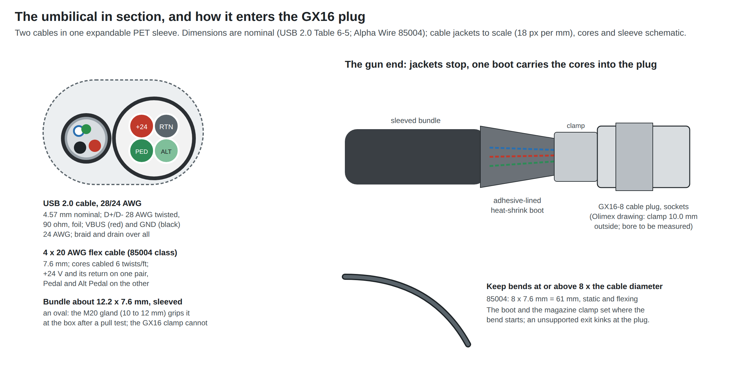
The umbilical is the part of a wired gun that the player handles most and the designer thinks about least. It is also where three different electrical regimes share one sleeve: a transmission line at 12 Mbit/s, a 5 V supply whose ground the USB specification holds to 125 mV of drop, and a pulsed 24 V supply carrying a couple of amps. This volume sizes each, then chooses a cable that will survive being swung around a living room.
General cable drop for solenoid leads, including the familiar table of loop resistance by gauge, is in Power Supplies Vol 2, section 2.8, and is not repeated. What is new here is the USB half of the cable, what the drop means once the stage is regulated (D13), and the mechanical side.
2.1 What the Cable Has to Do
Table 1 — 2.1 What the Cable Has to Do
| Requirement | Number | Source |
|---|---|---|
| Data pair impedance | 90 Ω ± 15 % differential, shielded, twisted | USB 2.0 §7.1.1.11 |
| One-way delay of the data pair | ≤ 26 ns, and ≤ 5.2 ns per metre | USB 2.0 §7.1.1.1 and §7.1.161 |
| Ground drop, host to device, all cables | ≤ 125 mV | USB 2.0 §7.2.2 (VGNDD)1 |
| 24 V loop resistance | as low as the cable’s weight allows; the stage needs headroom | 2.4 |
| 24 V return | its own conductor, never shared with USB ground | Power Supplies Vol 5 |
| Pedal lines | two conductors, any gauge | Controls and Inputs Vol 6 |
| Length, gun to junction box | 3 m | 2.9 |
| Survives | hand flexing at the gun end, being stepped on, and a 40 N tug | 2.6, 2.8 |
The 40 N figure is not a requirement anyone wrote for a light gun. It is the USB specification’s cable pull-out test: an axial load of 40 newtons for one minute with no damage to the plug’s cable clamp.1 It is a sensible floor for a cable a player will trip over.
2.2 The Build: Two Cables in One Sleeve
The proposed umbilical is two off-the-shelf cables in one braided sleeve:
- A USB 2.0 cable of the 28/24 AWG construction, bought long and cut: 28 AWG twisted data pair under foil, 24 AWG VBUS and ground, braid and drain over all. Monoprice’s product 5440 is a widely sold example, a 15 ft (4.6 m) A-to-B cable described as “28/24AWG”; its own page refused automated reading on 2026-10-19, so its price is to be read at order time. Any cable that states 28/24 or 28/22 and is shielded will do. The B end is cut off; the A end stays and becomes the plug into the PC.
- A four-core 20 AWG flexible cable for the 24 V pair and the pedal pair. The datasheet-backed choice is Alpha Wire’s Xtra-Guard Flex 85004: four 20 AWG cores of 63/38 stranding, cabled at a minimum of 6 twists per foot, a 0.300 in (7.6 mm) PVC jacket, a minimum bend radius of eight times the diameter static and flexing, a maximum pull of 32 lb, and a UL AWM 2587 “constant flexing” rating.2
This is the arrangement GUN4IR ships with its GC45 set (“3m USB and power cables, tied together in a nice sleeve”; Vol 1, 1.6), with the difference that the power cable here also carries the pedal.
Why not one cable with everything in it: there is no stocked jacketed cable that contains a real 90 Ω USB pair beside 20 AWG power cores at a hand-held diameter. The candidates that come close are compared in 2.10.
2.3 The 5 V Side: USB’s Own Budget
The USB specification limits the voltage drop on the ground conductor between host and device to 125 mV, and lists the maximum resistance it allows for each gauge of cable conductor (Table 6-6: 28 AWG 23.20 Ω per 100 m, 26 AWG 14.60, 24 AWG 9.09, 22 AWG 5.74, 20 AWG 3.58).1 Those maxima, not copper’s nominal values, decide the gauge.
The USB conductors here run about 4.0 m from PC to gun: roughly 1 m from the PC to the junction box, 3 m of umbilical, plus a 150 mm micro-USB pigtail inside the gun and one GX contact (20 mΩ, Olimex’s figure for its GX16; Vol 3).
Table 2 — 2.3 The 5 V Side: USB's Own Budget
| VBUS/GND gauge | Ground drop at 150 mA (the gun’s estimated draw) | Ground drop at 500 mA (a high-power device) | Verdict for 4 m |
|---|---|---|---|
| 28 AWG | 147 mV | 491 mV | Fails even at the gun’s own draw |
| 26 AWG | 96 mV | 319 mV | Passes at 150 mA, little margin |
| 24 AWG | 63 mV | 209 mV | Passes at the gun’s draw with half the budget spare |
| 22 AWG | 43 mV | 142 mV | Comfortable |
| 20 AWG | 30 mV | 99 mV | Meets the spec even as a high-power device |
From wired_calcs.py, at the specification’s maximum resistances. The 150 mA is Power Supplies Vol 1’s estimate for Pico, camera and LEDs; rumble, solenoid and port run from 24 V and are not in it.
Read to the letter of the specification for a device drawing the full 500 mA, a 4 m cable needs 22 AWG power conductors (the 125 mV limit at 500 mA allows 4.36 m of 22 AWG but only 2.75 m of 24 AWG). The gun draws about a third of that, so 28/24 is adequate and 28/22 is better if it is available at the same price. 28/28 cables, the thin ones sold as charge leads, fail outright at this length and are the commonest reason a long USB lead browns out a device.
The ground drop matters more than its size suggests. It is the offset between the gun’s ground and the PC’s, the same quantity that pulse current in a shared return drives to volts (Power Supplies Vol 5). Keeping the 24 V return on its own conductor keeps this number at tens of millivolts. Vol 5 shows how much offset the full-speed receiver tolerates.
2.4 The 24 V Side: What the Drop Costs a Regulated Stage
With an unregulated low-side switch, every volt lost in the cable is force lost at the coil, which is why Power Supplies Vol 2 treats cable drop as a loss of kick. With the regulated DRV8251A stages decided in D13, the driver sets the current, and the supply voltage becomes only headroom: the stage can hold its set current as long as the voltage at the gun covers the coil’s resistance and the bridge’s on-resistance at that current (Solenoid Recoil Vol 8).
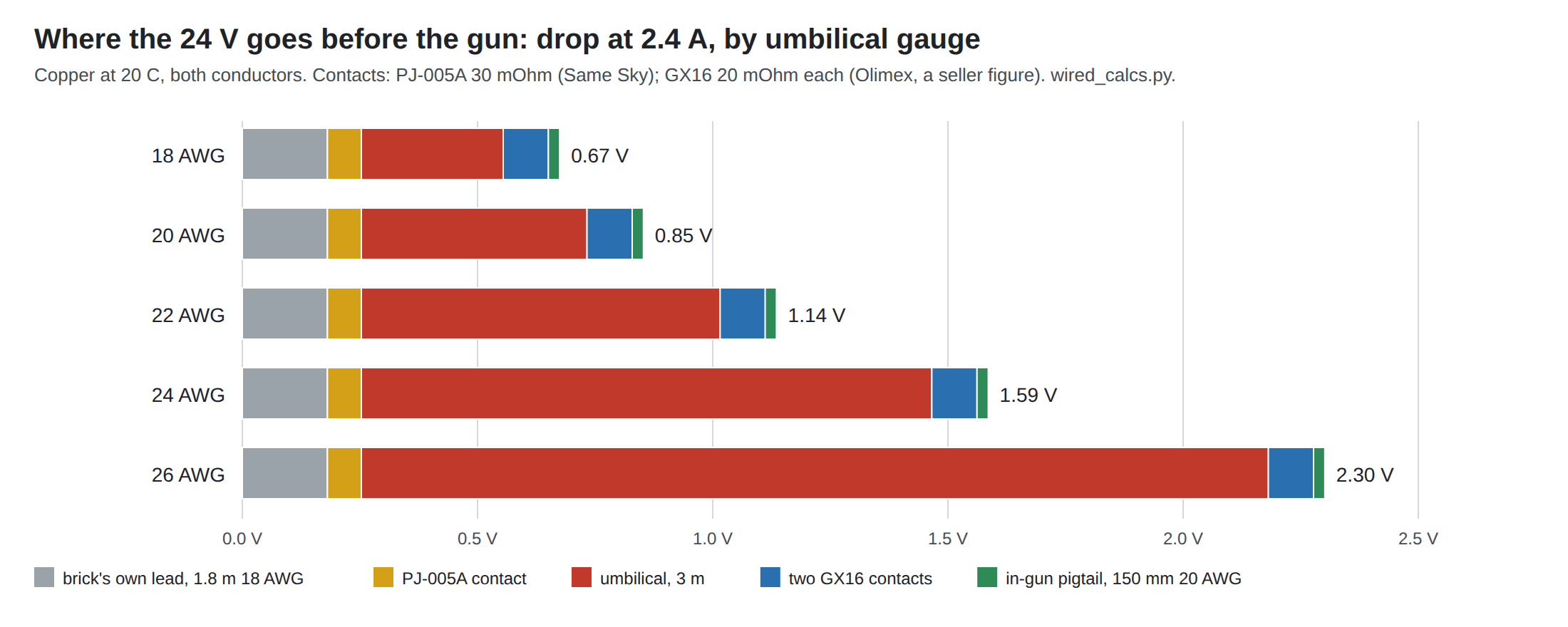
The whole loop at 2.4 A, brick to J12, with the umbilical as the variable:
Table 3 — The whole loop at 2.4 A, brick to J12, with the umbilical as the variable
| Umbilical gauge | Umbilical loop | Total loop | Drop at 2.4 A | Voltage at J12 | Largest hot coil the stage can regulate at 2.4 A |
|---|---|---|---|---|---|
| 18 AWG | 126 mΩ | 281 mΩ | 0.67 V | 23.33 V | 9.27 Ω |
| 20 AWG | 200 mΩ | 355 mΩ | 0.85 V | 23.15 V | 9.19 Ω |
| 22 AWG | 318 mΩ | 473 mΩ | 1.14 V | 22.86 V | 9.08 Ω |
| 24 AWG | 505 mΩ | 661 mΩ | 1.59 V | 22.41 V | 8.89 Ω |
| 26 AWG | 803 mΩ | 959 mΩ | 2.30 V | 21.70 V | 8.59 Ω |
Copper at 20 °C; 24.0 V at the brick; the brick’s 1.8 m 18 AWG lead; PJ-005A contact 30 mΩ (Power Supplies Vol 2); two GX contacts at 20 mΩ each; the DRV8251A’s typical 225 mΩ high side plus 225 mΩ low side (Reference Electronics Vol 5). “Hot” means the resistance the coil has at its working temperature, which for copper is about 8 % above its cold value for a 20 °C rise and 16 % for a 40 °C rise.
The finding: under regulated drive, the umbilical’s gauge barely matters electrically. Going from 26 AWG to 18 AWG moves the largest coil the stage can hold at 2.4 A from 8.6 Ω to 9.3 Ω, an 8 % change. The bridge’s own 0.45 Ω and the brick’s voltage are larger terms than the cable. The same calculation at the 18 V bottom of the D14 window (a reduced supply, not the brick) gives 6.8 Ω for 18 AWG and 6.4 Ω for 24 AWG.
Two caveats keep the table conservative. The cable carries 2.4 A only while the regulated stage is ramping the coil up at full supply voltage; once it is holding, the bridge chops, the 1000 µF reservoir supplies the ripple, and the cable carries an average that is smaller than the coil current (LiPo Batteries Vol 3 works the same relation for a pack). And the 20 mΩ GX contact figure is a seller’s, for a four-pin part; it should be measured on the part bought (Vol 6, bench check W3).
So the gauge is chosen on other grounds: 20 AWG is heavy enough that the drop is under a volt and the conductors are mechanically robust at the solder cups, and light enough that the four-core cable stays at 7.6 mm. 18 AWG buys 0.18 V and costs stiffness; 22 AWG and finer save little weight and make the USB-side argument of 2.3 (a separate return that stays quiet) depend on joints that are harder to make well.
Heating is not a constraint at any of these gauges: 2.4 A in short pulses at autofire duty is well under 2 A RMS, and 20 AWG flexible cable carries several amps continuously.
2.5 Shielding and Twisting
The USB cable brings its own shield. A 28/24 cable has a foil over the data pair and a braid and drain over everything (USB 2.0 §6.6). Where that shield is terminated is a grounding question and is settled in Vol 5: at the PC end through the USB-A plug’s shell, as made, and folded back and insulated at the GX end, because the eight-pin GX has no pin to spare for it and the printed gun has no metal chassis to take it.
The power pair is twisted, not shielded. What protects the data pair from the pulse current beside it is geometry: a small loop on the 24 V side (its two conductors cabled together at 6 twists per foot in the 85004) and a differential receiver on the USB side. A shield on the power pair would add weight and stiffness for little; the field it would contain is mostly magnetic, at audio frequencies, and a foil shield does little against that. Keeping the loop small is what helps.
The pedal pair rides in the same jacket as the 24 V pair. Its lines see the pulse edges by coupling. They are switch inputs read through a 32-read firmware filter, with the 1 kΩ and 10 nF network and a TVS at the jack fitted for exactly this reason (Controls and Inputs Vol 5, 5.7). The proposed carrier draws that network; nothing more is needed in the cable.
2.6 Flex Life: What the Datasheets Say
A light-gun cable fails in one place: where it leaves a rigid part. Near the plug the cable is bent over a short radius every time the gun is swung, and stranded copper work-hardens there and breaks one strand at a time. The only published numbers come from industrial cable makers, and they are measured on motion-control rigs, not on hand-held leads, so they rank cables rather than predict years.
Table 4 — 2.6 Flex Life: What the Datasheets Say
| Cable type | Published flex figure | Diameter | Bend radius | Verdict |
|---|---|---|---|---|
| Consumer USB 2.0 cable (28/24, PVC) | None published by the sellers checked | 4.57 mm nominal for 28/24 (USB 2.0 Table 6-5) | not stated | Used for the data pair because nothing else gives a true 90 Ω pair; protect its exit |
| Alpha Wire Xtra-Guard Flex, 85000 series (85004: 4 × 20 AWG) | “Rated for up to 14 million flex life cycles (85000 series)“ | 7.6 mm | 8 × D static and dynamic (61 mm) | Pick for the power and pedal cable |
| Alpha Wire Xtra-Guard Flex, 86000 series (shielded) | “up to 6 Million flex life cycles (86000 series)“ | larger | Shield not needed (2.5) | |
| igus chainflex CFBUS family | rated for drag chains | 8.5 to 10.5 mm on distributor listings | 4 to 7 × D | Too thick and stiff for a hand-held lead |
| Cat 6A S/FTP patch cable | none | about 6 to 7 mm | One jacket, 100 Ω pairs within the USB tolerance, but 24 to 26 AWG conductors for the 24 V pair; see 2.10 | |
| Coiled (retractile) cord | varies by maker | Stores length; pulls the gun with a constant force; not chosen |
Alpha Wire’s figures are from the series’ product page;2 the page does not state the test method behind them. The practical reading is that a constant-flex rated cable resists work-hardening far better than an appliance cord of the same gauge, and that both fail first where they are bent tightest. That is what 2.8 is for.
2.7 The Sleeve
An expandable PET braided sleeve holds the two cables together, stops them twisting round each other, and takes the scuffing. Two points of fit:
- Size. The bundle is an oval of about 12.2 by 7.6 mm. A sleeve of 1/2 in (13 mm) nominal expands over it with room to slide; a 3/8 in sleeve will not pass over the 85004.
- Ends. PET braid frays when cut cold. Cut it with a hot knife and finish both ends under adhesive-lined heat shrink, which at the gun end is also the boot of 2.8.
Expandable sleeve is sold by the metre by many cable-management suppliers; no single maker’s page was read for this volume, so no price is given here. It is the cheapest item in the cable.
2.8 Strain Relief at Both Ends
At the gun end, the force path matters more than the clamp. With a panel-mount GX in the base plate (MP7 Printed Build Vol 5, 5.6), a tug on the umbilical goes from the cable, through the plug’s own clamp and its coupling ring, into the panel connector and its nut, and so into the printed base plate. Three things follow:
- The plug’s clamp grips a boot, not the bundle. The two jackets cannot both enter a GX16 plug: Olimex’s drawing gives its cable clamp an outside dimension of 10.0 mm,3 so the bore it grips is smaller, against a 12.2 mm bundle. The jackets are therefore stopped about 25 mm short of the plug, the cores continue inside an adhesive-lined heat-shrink boot (3:1 or 4:1), and the clamp grips the boot. The USB pair keeps its twist and foil up to the solder cups (Vol 5 gives the limit, about 25 mm untwisted). The clamp’s real bore is to be measured on the plugs bought.
- The boot sets the bend. Its stiffness tapers the bend so that the cable’s first 60 mm out of the plug cannot fold tighter than the 85004’s 61 mm minimum radius. A bare exit kinks at the plug, and that is where flex failures start.
- The base plate takes the tug. The panel connector’s nut and the plate around it should be designed for the USB pull-out figure, 40 N, with margin; in PETG that means a boss of full wall thickness round the connector hole, not a thin printed skin. Inside the magazine, the short harness from the panel connector to the carrier is clamped to a printed boss (P-MP7-6) so that no pull reaches the carrier even if the panel nut loosens.
At the box end, the sleeved bundle enters through an M20 nylon cable gland with a 10 to 12 mm clamping range (Vol 4). An oval bundle in a round seal grips by deformation; a pull test (2.1’s 40 N, applied by hand with a luggage scale) confirms it holds. If it slips, a turn of self-amalgamating tape under the seal fixes it.
At the PC end there is nothing to design: the USB-A plug is the cable maker’s, moulded, and the junction box takes any pull before it reaches it.
2.9 Why Three Metres
Three metres is the gun-to-box length, chosen from the playing distance. The aiming dives work the gun at 1.5 to 3.5 m from a 55-inch screen (Aiming Maths and Calibration Vol 7), and the box lies on the floor near the PC, which is usually under or beside the screen. Three metres reaches a player standing at 2.5 m with slack for the gun to be raised and swung.
The electrical limits are well clear of it. The USB pair runs about 4 m in total against the specification’s 26 ns one-way limit, which at 5.2 ns per metre is 5 m; the 24 V drop is under a volt; the ground drop at the gun’s draw is 63 mV. A 4 m umbilical would still pass all three, and anything longer should move the box, not lengthen the USB pair.
2.10 Why This, and Why Not the Others
Criteria: a true 90 Ω pair for USB; VBUS and ground at 24 AWG or heavier over 4 m; a 24 V pair that is not shared with USB ground; two pedal conductors; a published flex rating where one exists; a diameter and stiffness a player can swing; parts that can be bought without a cable-assembly house.
Table 5 — 2.10 Why This, and Why Not the Others
| Candidate | Verdict | Reason |
|---|---|---|
| USB 2.0 cable, 28/24, plus a 4 × 20 AWG constant-flex cable (Alpha Wire 85004 class), in one PET sleeve | Pick (proposed, row WD-1) | Real USB pair and shield; 24 V return on its own conductor; pedal on spare cores; flex-rated power cable; both parts stocked. The bundle is 12.2 mm across, so the gun end needs the boot of 2.8. |
| The same with a 2 × 18 AWG power cable and a separate pedal pair | Rejected | Three cables in the sleeve, and the 0.18 V saved over 20 AWG buys nothing under regulated drive (2.4). |
| A 4 × 20 AWG cable without a flex rating (appliance or alarm cable) | Fallback | Electrically identical and lighter; fails sooner at the plug. Acceptable for the first bench cable. |
| One Cat 6A S/FTP patch cable for everything | Rejected | One slim jacket and pairs whose 100 Ω sits within USB’s 90 Ω ± 15 %, but every conductor is 24 to 26 AWG: the 24 V loop rises to 0.5 to 0.8 Ω, VBUS and ground are 26 AWG at best (96 mV at the gun’s draw over 4 m), and there are exactly eight conductors with none spare. |
| A shielded multicore with untwisted cores carrying D+ and D− | Rejected | No defined impedance on the data pair, so nothing guarantees the full-speed eye at 3 m (Vol 5); many builds get away with it, which is not the same thing. |
| Industrial hybrid or chainflex bus cable | Rejected | 8.5 to 10.5 mm and stiff; designed for drag chains, not hands. |
| A 28/28 USB cable | Rejected | Fails the 125 mV ground budget at 4 m even at 150 mA (2.3). |
| Coiled cord | Rejected | Pulls on the gun all the time, and its springback swings the gun’s weight distribution. |
2.11 What Could Not Be Verified
- Prices for the Monoprice 5440 cable, the Alpha Wire 85004 and PET sleeving: the seller pages refused automated reading on 2026-10-19 (Monoprice) or price by the spool (Alpha Wire). Read at order time.
- The GX16 plug’s clamp bore. Only the clamp’s 10.0 mm outside dimension is on Olimex’s drawing.
- Alpha Wire’s flex-cycle test method. The page gives “up to 14 million” without the bend radius, speed or failure criterion.
- The gun’s 5 V draw is Power Supplies’ estimate (150 mA), not a measurement.
- The GX contact resistance (20 mΩ) is Olimex’s figure for a four-pin GX16, not for the eight-pin part.
Footnotes
-
USB Implementers Forum, Universal Serial Bus Specification Revision 2.0 (
usb_20.pdfinusb_20_20250603.zip): §6.6.2 Table 6-5 (nominal cable diameters), §6.6.3 Table 6-6 (conductor resistance), Table 6-7 (cable pull-out, EIA 364-38, 40 N for one minute; durability 1,500 cycles), §7.1.1.1 (90 Ω ± 15 %, 26 ns), §7.1.16 (“The cable delay must also be less than 5.2 ns per meter”), §7.2.2 (125 mV VGNDD). https://www.usb.org/document-library/usb-20-specification (downloaded 2026-10-19). ↩ ↩2 ↩3 ↩4 ↩5 -
Alpha Wire, Xtra-Guard Flex 85004 product page: construction (4 × 20 AWG 63/38 bare copper, cabled 6.0 twists/foot minimum, jacket 0.300 ± 0.017 in, PVC), “Bend Radius 8X Cable Diameter (static), 8X Cable Diameter (dynamic)”, “Pull Tension 32 Lbs, Maximum”, UL AWM 2587; series text “Rated for up to 14 million flex life cycles (85000 series), up to 6 Million flex life cycles (86000 series)”. https://www.alphawire.com/en/Products/Cable/Xtra-Guard-Performance-Cable/Xtra-Guard-Flex/85004 (read 2026-10-19). ↩ ↩2
-
Olimex, CONNECTOR-GX16-4 product page and dimension drawing
gx-connector-dimension.jpg(cable clamp 10.00 mm; M16 × 1 thread; contact resistance 20 mΩ; “20 A / 220 V”; €1.55 a pair). https://www.olimex.com/Products/Components/Connectors/CONNECTOR-GX16-4/ (read 2026-10-19). ↩
Comments (0)