Fully Wired · Volume 4
The Far-End Junction Box — Where the Brick, the PC and the Pedal Meet the Cable
A passive breakout in a three-dollar plastic box: what goes in it and what deliberately does not, why it must not be metal, the parts with dated prices, the build, and the hot-plug hazard at the barrel jack
D31 moves the barrel jack from the gun to “the far end” of the cable, where “the brick’s own 5.5 × 2.1 mm plug and the PC’s USB meet the cable”. CI-7 adds the pedal’s jack to the same place. Something has to hold those three and clamp the umbilical. This volume designs that something, and the main design decision turns out to be what to leave out of it.
4.1 What the Box Is For
Table 1 — 4.1 What the Box Is For
| Job | How |
|---|---|
| Accept the brick’s 5.5 × 2.1 mm plug | A panel barrel jack, J1 |
| Accept the pedal’s 3.5 mm TRS plug | A panel jack, J2 (tip Pedal, ring Alt Pedal, sleeve ground; Controls and Inputs Vol 6) |
| Pass USB to the PC | The umbilical’s USB cable runs straight through and out to its own USB-A plug |
| Take the pull off all three | An M20 gland on the umbilical, a bushing on the USB lead, panel nuts on the jacks |
| Show whether the brick is live | An LED across the 24 V pair, so step 1 of the mating order can be checked at a glance |
| Carry the mating order | Printed on the lid |
| Sit on the floor or under a desk | A flanged box that can be screwed down |
4.2 The Circuit
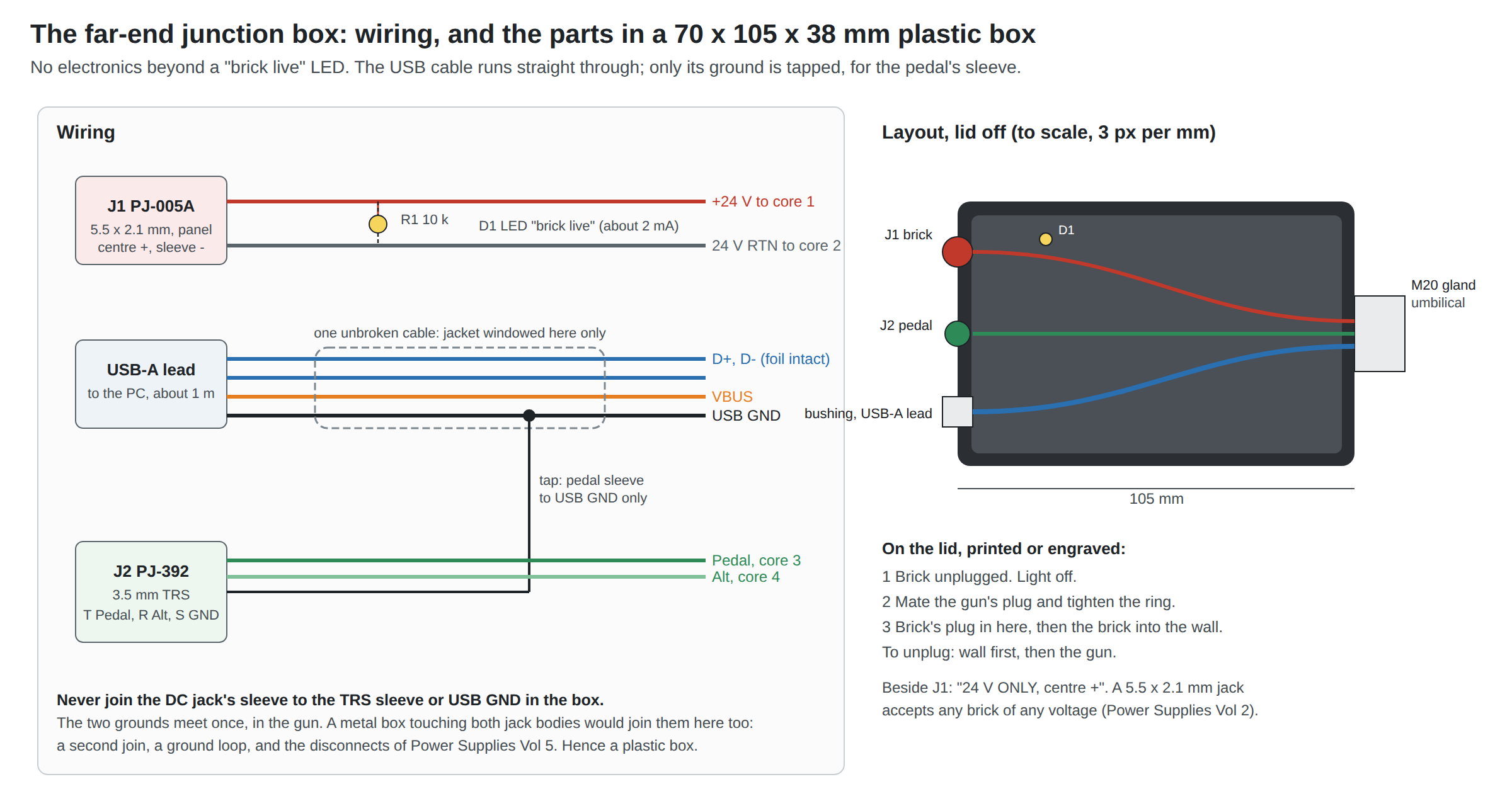
Four nets, and one rule:
- 24 V and 24 V return from J1’s centre and sleeve to cores 1 and 2 of the four-core cable. Polarity per the bricks: centre positive (Power Supplies Vol 2).
- D1 and R1 across the 24 V pair: a 3 mm LED and 10 kΩ, about 2.2 mA and 53 mW at 24 V. It is lit whenever the brick is live, which is the state in which the GX must not be mated.
- USB: untouched. The USB cable enters through the bushing from the PC side and leaves through the gland in the umbilical’s sleeve. Only its outer jacket is opened, for about 20 mm in the middle of the box, to reach the ground conductor.
- Pedal: J2’s tip to core 3, ring to core 4, and sleeve to the USB cable’s ground conductor at that window, soldered and sleeved.
The rule: J1’s sleeve (the brick’s 0 V) is joined to nothing in the box except core 2. The two grounds, brick and USB, meet once, in the gun, at the single join (Power Supplies Vol 5; D34). A second join in the box would make a loop through the cable’s two ground conductors, and pulse current would divide between them, half of it in the USB ground, which is precisely what the separate return exists to prevent.
The pedal’s sleeve goes to USB ground, not to the 24 V return, for a related reason. The pedal input in the gun is referenced to logic ground. Returned through core 2, it would read low with the 24 V return’s pulse drop added (up to about 0.5 V at 2.4 A on 3 m of 20 AWG; Vol 2), which is inside the switching threshold’s margin but pointlessly close to it.
4.3 Why Plastic: the Box Must Not Join the Grounds
The obvious enclosure for a small floor box is a diecast aluminium one of the 1590 family, cheap and nearly indestructible. It is the wrong choice here. Panel jacks bolt through the wall with metal bushings and nuts, and on many jacks the bushing is the sleeve contact. Bolt the barrel jack and the TRS jack into one metal box and the box joins their sleeves: brick 0 V to USB ground, the second join of 4.2, made by the enclosure without a wire in sight.
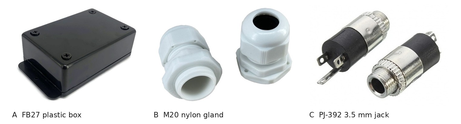
It can be avoided in metal with insulating shoulder washers on every jack, but a plastic box avoids it by default and costs less. The pick is a flanged ABS box of 70 × 105 × 38 mm (usable 63 × 98 × 29 mm), Future Box FB27 as sold by Tayda (parts, 4.5); any plastic box of about that size will do, and so will one printed in PETG on the lab’s Prusas.
4.4 What Is Deliberately Left Out
Table 2 — 4.4 What Is Deliberately Left Out
| Candidate | Left out because |
|---|---|
| A fuse | The brick is the current limit: its over-current trip band starts at about 2.63 A for the GST60A24 (Power Supplies Vol 2), so a crushed umbilical shorting core 1 to core 2 sends the brick into hiccup, not the cable into flames. The gun has its own fuse, F1, on the carrier. A fuse in the box would protect only the umbilical, and the brick already does. |
| A TVS on the 24 V pair | The gun’s input TVS (SMBJ28A, D33) is at J12, where the stages are. A second one in the box would clamp the same rail 3 m further from the parts it protects. |
| A power switch | A switch in the 24 V line looks convenient, and it would make step 3 of the mating order unnecessary. It is left out for the first build because it adds a contact in the pulse loop and lets the GX be mated with the brick in the wall and only a switch, easily left on, between them. Revisit if the order proves tedious (Vol 6, question 3). |
| A USB hub or USB electronics | Nothing needs them. The USB cable passes through so the data pair stays one uninterrupted, impedance-controlled cable from PC to gun. |
| Ferrites | Power Supplies Vol 5 explains why they do not cure a shared-return disconnect, and the architecture has no shared return. Add one on the USB-A lead only if a radiated-emissions problem is ever found. |
| A TVS on the pedal lines at J2 | Controls and Inputs Vol 5 calls a TVS at the pedal jack “cheap insurance” against ESD from a foot. With the jack now in the box, it belongs here, between each pedal line and the tapped USB ground. The part is Reference Electronics’ to choose; the box leaves room for two SOD-123 parts on a scrap of perfboard behind J2. Fitted, part to be named (question for the carrier design). |
4.5 Parts, With Dated Prices
Prices as listed on 2026-10-19 on the pages named. Tayda’s pages could be read; DigiKey, Mouser and Hammond refused automated reading that day, so maker-branded alternatives are named without prices.
Table 3 — 4.5 Parts, With Dated Prices
| Ref | Part | Pick | Price, 2026-10-19 | Why |
|---|---|---|---|---|
| Box | Flanged ABS box, 70 × 105 × 38 mm | Future Box FB27 (Tayda A-3622)1 | $2.94 | Plastic (4.3); flanges for screwing down; room for a 20 mm gland hole in a 38 mm end wall |
| J1 | Panel barrel jack, 5.5 × 2.1 mm, 5 A | Same Sky PJ-005A2 | not readable | The part Power Supplies chose for the gun before D31: 5 A, 24 V, 30 mΩ contact, 5,000 cycles, panel nut; it moves to the box with its datasheet |
| J1 alt | the same, unbranded | Tayda DC-099 (A-5245)3 | $0.06 | ”30VDC 5A” on the listing; no maker datasheet; acceptable for a bench cable |
| J2 | 3.5 mm stereo enclosed chassis jack | PJ-392 (Tayda A-2585)4 | $0.15 | Panel thread and nut; three contacts for tip, ring and sleeve |
| Gland | Nylon cable gland, M20 × 1.5, 10–12 mm | Tayda A-80795 | $0.65 | The sleeved bundle (12.2 × 7.6 mm) is at the top of its range: grips once tightened; pull-test it |
| Bushing | Strain-relief bushing for round cable | PINGOOD 5R-4/RH (Tayda A-4409)6 | $0.10 | Snaps into a hole and grips the USB-A lead; listed for 6.4 mm cable, so build the 4.6 mm USB lead up with heat shrink to fit |
| D1 | 3 mm LED, any colour | stock | cents | |
| R1 | 10 kΩ, 0.25 W | stock | cents | 53 mW dissipated |
| Lid label | engraved on the lab’s CO2 laser, or printed | The mating order (Vol 1, 1.7) |
Box total, excluding the PJ-005A: about $4 at Tayda’s prices. The umbilical’s cables, the GX pair and the brick are priced in Vol 6’s whole-system table.
4.6 The Barrel Jack and Hot-Plugging
The barrel jack is the one connector in the system that will be mated live, sooner or later, however clearly the lid is labelled: someone will plug the brick into the wall first and the barrel in second. Two things happen when they do.
A spark at the jack. The gun’s 1000 µF reservoir is at 0 V and the brick’s output is at 24 V; the first contact charges the reservoir through the cable’s resistance, a few hundred milliohms, with a peak current limited mainly by the brick’s own output capacitance and the cable’s inductance. The arc pits the jack’s centre pin. Over thousands of cycles that raises its contact resistance, the 30 mΩ of the datasheet.
A voltage overshoot at the gun. A source switched suddenly into a cable with a capacitor at its end forms an LC circuit, and with a low-loss capacitor the voltage at the capacitor can ring to nearly twice the source voltage. Linear Technology’s Application Note 88 documents exactly this for ceramic input capacitors on a hot-plugged supply lead.7 Twice 24 V is beyond the SMBJ28A’s clamp and the DRV8251A’s 50 V absolute maximum. What saves the gun is that its reservoir is an electrolytic or polymer capacitor whose equivalent series resistance damps the ring, and that the TVS clamps what is left. How much overshoot actually occurs with this cable and this reservoir is a measurement, not a calculation, because it depends on the reservoir’s ESR and the cable’s inductance, neither of which is known yet (bench check W5).
Hence step 3 of the mating order: plug the barrel in while the brick is unpowered, so the brick’s own soft start charges the reservoir. The LED makes a breach visible.
4.7 Building It
- Drill. One end wall: J1 (the PJ-005A’s panel hole per its datasheet), J2 (the PJ-392’s thread, 6 mm class; measure), the bushing’s hole (per its listing), and a 3 mm hole in the lid or wall for D1. The other end wall: 20 mm for the M20 gland. Keep the jacks low in the wall so the plugs do not lever the lid off.
- Pass the cables. Feed the USB-A lead in through the bushing, and the sleeved umbilical in through the gland. Leave the sleeve stopping just inside the gland’s seal.
- Window the USB cable. In the middle of the box, slit 20 mm of outer jacket, find the ground conductor (black in most cables) without disturbing the braid round the data pair more than necessary, strip 5 mm, and solder J2’s sleeve wire to it. Sleeve the joint and close the window with heat shrink split and wrapped, or self-amalgamating tape.
- Wire J1 and J2 to cores 1 to 4, D1 and R1 across J1’s pins.
- Check with a meter, before the gun is ever connected: J1’s sleeve open to J2’s sleeve and to the USB-A plug’s ground pin (the rule of 4.2); J1 centre to the GX socket at the centre; each pedal contact to its GX socket; the USB-A plug’s four pins to their GX sockets. Then plug the brick in and confirm 24 V between the GX centre socket and position 7, and the LED lit.
- Pull-test the gland and the bushing by hand at about 40 N (Vol 2, 2.1).
- Label the lid.
4.8 Why This, and Why Not the Others
Criteria: D31 (the brick’s plug and the PC’s USB meet the cable at its far end); CI-7 (the pedal jack there too); no second join between the grounds; no break in the USB pair; robust to being kicked; cheap; buildable in an evening.
Table 4 — 4.8 Why This, and Why Not the Others
| Candidate | Verdict | Reason |
|---|---|---|
| Passive plastic box: barrel jack, TRS jack, LED, USB passing through, gland and bushing | Pick (proposed, WD-3) | Does every job of 4.1 and nothing else; cannot join the grounds; about $4 plus the jack. |
| The same in a diecast aluminium 1590A or 1590B | Rejected | $4.29 and $5.49 at Tayda, but the metal joins the jack sleeves (4.3) unless every jack is insulated. |
| A moulded Y-split, as on Ultimarc’s AimTrak lead (Vol 1, 1.6) | Not buildable | Needs an overmoulding tool. A heat-shrink Y-split is possible but has no place for the pedal jack or a gland. |
| USB through a panel USB-B socket on the box, with a separate USB lead to the PC | Rejected | Adds a connector pair and a break in the controlled-impedance pair; buys only a detachable PC lead. |
| A printed box | Equivalent | Same function; worth it if a shape that clips to a desk leg is wanted. |
| Electronics in the box (fuse, switch, hub, protection) | Rejected for now | Each one either duplicates a protection the brick or the carrier already provides, or adds a contact in the pulse loop (4.4). |
4.9 What Could Not Be Verified
- The PJ-005A’s current price, and whether its panel bushing is a sleeve contact (it does not matter in a plastic box).
- The PJ-392’s sleeve-to-bushing connection and its thread size: read the Tayda datasheet link or measure.
- The bushing’s real grip range: Tayda lists only “6.4mm”.
- The pedal TVS part (to be chosen with the carrier).
- The hot-plug overshoot with the real reservoir and cable (W5).
Footnotes
-
Tayda Electronics, “Project Plastic Box 27”, Future Box FB27, SKU A-3622: “Dimension (W x L x H): 70 X 105 X 38 mm. Usable Area (W x L x H): 63 X 98 X 29 mm”, $2.94. https://www.taydaelectronics.com/project-plastic-box-27.html (read 2026-10-19). ↩
-
Same Sky (formerly CUI Devices), PJ-005A datasheet, as cited in Power Supplies Vol 2 section 2.12 (5 A, 24 Vdc, 30 mΩ, 5,000 cycles). ↩
-
Tayda Electronics, “DC Power Jack 2.1mm*5.5mm Panel Mount Round DC-099”, SKU A-5245, “Rated Voltage: 30VDC 5A”, $0.06. https://www.taydaelectronics.com/dc-power-jack-2-1mm-x-5-5-mm-round-type-panel-mount-dc-099.html (read 2026-10-19). ↩
-
Tayda Electronics, “PJ-392 3.5mm Stereo Enclosed Chassis Socket Jack”, SKU A-2585, $0.15. https://www.taydaelectronics.com/pj-392-3-5mm-stereo-enclosed-chassis-socket.html (read 2026-10-19). ↩
-
Tayda Electronics, “Cable gland for holding various wires together”, SKU A-8079: “Thread Size: M20x1.5 … Max Cable Diameter: 12mm Minimum Cable Diameter: 10mm IP Rating: IP68”, $0.65. https://www.taydaelectronics.com/cable-gland-for-holding-various-wires-together.html (read 2026-10-19). ↩
-
Tayda Electronics, “Black Strain Relief Bushing for Round Shape”, PINGOOD 5R-4/RH, SKU A-4409, “Cable Size: 6.4mm”, $0.10. https://www.taydaelectronics.com/black-strain-relief-bushing-for-round-shap.html (read 2026-10-19). ↩
-
Goran Perica, Ceramic Input Capacitors Can Cause Overvoltage Transients, Linear Technology Application Note 88, March 2001 (now Analog Devices), https://www.analog.com/media/en/technical-documentation/application-notes/an88f.pdf . Identified 2026-10-19 by search; the PDF itself was not read for this volume, so its figures are not quoted. Listed for the Library. ↩
Comments (0)