Fully Wired · Volume 5
Signal Integrity, Latency and Grounding Down the Cable
Why full-speed USB shrugs off an aviation connector but not an arbitrary pair of wires, how much ground offset its receiver tolerates, what three metres of cable add to the gun's latency (a millisecond of polling and twenty nanoseconds of wire), and where every ground in the system meets
The brief for this volume was a worry: USB through a connector that was never designed for it, over three metres, beside a cable carrying amps of pulsed current. The answer is that full-speed USB is forgiving in exactly the ways that matter here and unforgiving in one way that does not apply if the cable is built as Vol 2 describes. The numbers below are from the USB 2.0 specification unless another source is named.1
5.1 Full Speed, in Numbers
The RP2040 has a full-speed USB device controller and PHY: 12 Mbit/s, the speed of USB 1.1, which USB 2.0 carries forward unchanged.
Table 1 — 5.1 Full Speed, in Numbers
| Quantity | Value | Source |
|---|---|---|
| Bit time | 83.3 ns | 12 Mbit/s |
| Driver rise and fall, 10 to 90 % | 4 to 20 ns, matched within ± 10 % | §7.1.2.1, Table 7-9 |
| Driver output, low and high | below 0.3 V; above 2.8 V | §7.1.1 |
| Crossover voltage | 1.3 to 2.0 V | §7.1.2.1 |
| Receiver differential sensitivity | 200 mV | §7.1.4.1 |
| Receiver common-mode range | 0.8 to 2.5 V | §7.1.4.1, Table 7-7 |
| Cable impedance | 90 Ω ± 15 % differential; 30 Ω ± 30 % common mode | §7.1.1.1 |
| Cable one-way delay | ≤ 26 ns, and ≤ 5.2 ns per metre | §7.1.1.1, §7.1.16 |
| Ground drop, all cables | ≤ 125 mV | §7.2.2 |
Full speed is also source-terminated: each driver’s output impedance (28 to 44 Ω per line, including its series resistor) matches the cable, and the far end is not terminated. An edge travels down the cable, doubles at the open end, travels back and is absorbed at the driver. Everything in this volume follows from that arrangement and the 4 ns fastest edge.
5.2 The Cable Is a Transmission Line; the Connector Is Not
A piece of interconnect behaves as a lumped element, rather than a transmission line, when its delay is short against the signal’s rise time. A common engineering rule puts the boundary at about one sixth of the rise time. At the cable’s 5 ns per metre and full speed’s fastest 4 ns edge, that is about 13 cm; at the slowest, 20 ns, about 67 cm (wired_calcs.py).
- The 4 m of USB cable is 20 ns long, five times the fastest edge. It is a transmission line, and its impedance matters. It is also inside the 26 ns budget with room to spare.
- The GX16 and its solder cups are about 40 mm of untwisted, unshielded conductor (two contacts’ worth of pin and socket plus the cups at each end), about 0.2 ns. That is a small fraction of the 13 cm boundary. To the signal it is a few nanohenries of extra series inductance and a fraction of a picofarad, invisible against a 4 ns edge. The connector’s lack of a controlled impedance does not matter at full speed. It would matter at high speed (480 Mbit/s, with edges of a few hundred picoseconds), which the RP2040 does not use.
- The micro-USB pigtail inside the gun is 150 mm of real USB pair: just over the 13 cm boundary, and a correct pair anyway.
- The junction box does not touch the pair at all (Vol 4).
So the untwisted length at the GX is not a signal-integrity problem at 40 mm. It becomes one only if the pair is untwisted over a length comparable to the 13 cm boundary. A practical limit of about 25 mm untwisted at each side of the connector keeps the whole discontinuity well inside it, and is what Vol 3 asks for at the solder cups.
5.3 Why a Real USB Pair, Then
If the connector is invisible, why insist on a real USB cable for the 3 m run rather than two cores of the four-core power cable, or any pair in a multicore? Because the cable is not invisible. A mismatched line reflects part of each edge back at the source, where a mismatch with the driver reflects part of it again; the re-reflection arrives at the receiver one round trip (40 ns at 4 m) after the edge, inside the same 83 ns bit.
The reflection coefficient at a nominally 90 Ω source for several cable impedances (wired_calcs.py):
Table 2 — The reflection coefficient at a nominally 90 Ω source for several cable impedances (wiredcalcs.py)
| Pair impedance | Example | Source reflection coefficient |
|---|---|---|
| 70 Ω | a loosely twisted pair in a jacket | + 0.12 |
| 90 Ω | a USB cable | 0 |
| 100 Ω | a Cat 5e or Cat 6 pair | − 0.05 |
| 120 Ω | an untwisted pair of cores in a multicore | − 0.14 |
| 150 Ω | two cores far apart | − 0.25 |
None of these is catastrophic at full speed, and that is why so many hand-built guns work on whatever pair they were wired with. A 100 Ω data-cable pair is within USB’s 90 Ω ± 15 % and is effectively correct. What an arbitrary pair lacks is the rest of the specification: no stated impedance, no balance between the two conductors (USB allows 5 % resistance unbalance), no foil, and no guarantee against the next cable bought being different. A real USB cable costs a few dollars and removes the question. The cost argument runs one way.
5.4 How Much Ground Offset the Receiver Tolerates
The gun’s driver swings its lines between about 0 and 3.3 V relative to the gun’s ground, crossing at 1.3 to 2.0 V. The PC’s receiver sees those voltages relative to the PC’s ground. If the gun’s ground sits ΔV above or below the PC’s, everything the receiver sees moves by ΔV.
The receiver is guaranteed to work for a common-mode voltage between 0.8 and 2.5 V. The crossover sits at 1.3 to 2.0 V. So the margin is about 0.5 V in either direction: a ground offset of half a volt can push the signal’s common mode to the edge of the guaranteed range, and an offset of a volt or two takes it outside, at which point the receiver may misread packets, and the host treats the device as gone.
That is the mechanism behind Power Supplies Vol 5’s worked example, where a 2 A pulse returning through a 1.06 Ω shared ground conductor lifts the gun’s ground about 2.1 V: four times the margin. In the architecture of this dive, the ground offset is the logic current in the USB ground conductor alone, about 63 mV at the gun’s estimated 150 mA over 4 m of 24 AWG (Vol 2, 2.3), an eighth of the margin, and it does not change when the coil fires, because no pulse current flows in that conductor.
5.5 The Pulse Beside the Pair
With the returns separated, what remains is coupling: the 24 V pair’s changing current inducing voltage in the USB conductors that run beside it for 3 m.
- Magnetic coupling from the pulse’s edges (a regulated stage switches the coil’s current at its chopping rate, and the initial rise and the decay are fast) induces voltage in any loop the USB conductors form. In a twisted pair, adjacent twists cancel the differential part; what is left is mostly common mode, which the receiver rejects up to its 0.5 V margin. Twisting the 24 V pair (the 85004 cables its cores at 6 twists per foot) shrinks the source loop as well. The DRV8251A stages keep the fastest edges inside the gun: the coil’s current loop closes through C4 on the carrier (Reference Electronics Vol 8), and the cable sees the smoothed supply current.
- Electric coupling is what the USB cable’s foil and braid stop, provided the shield is terminated somewhere (5.6).
- The pedal lines are the exposed ones: unshielded, in the same jacket as the 24 V pair. They are switch inputs behind a 1 kΩ and 10 nF filter and a 32-read firmware filter (Controls and Inputs Vol 5), which is plenty for induced spikes of nanoseconds.
5.6 Every Ground, and Where They Meet
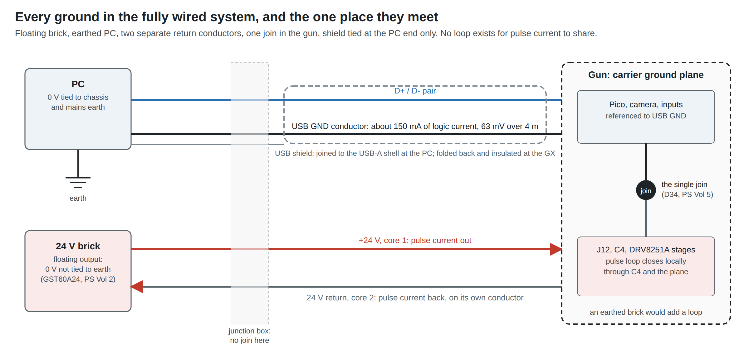
The grounding rules are Power Supplies Vol 5’s; what this section adds is where each one lands in the wired system.
Table 3 — 5.6 Every Ground, and Where They Meet
| Ground | Its reference | Where it goes | Why |
|---|---|---|---|
| PC 0 V | mains earth, through the PC’s supply | USB GND conductor, USB-A shell | Every host does this |
| Brick 0 V | nothing: the GST60A24’s output floats | 24 V return, core 2 | A floating brick means the pulse current has one path home, its own conductor. An earthed brick would add a second, through the house wiring, the PC and the USB ground (Power Supplies Vol 5, 5.5) |
| Junction box | none | joins nothing (Vol 4, 4.2–4.3) | Any join here is a second join |
| Gun | the carrier’s solid plane (D34) | USB GND and 24 V return both land on it: the single join | Required, so that the stages’ gate signals have a reference; Reference Electronics Vol 8 places it |
| USB shield | the PC’s chassis, through the USB-A shell | folded back and insulated at the GX | The GX has no spare pin, the printed gun has no chassis, and a shield bonded at the gun would be a second, parallel ground path between gun and PC. Tied at the host end it still drains electric-field pickup |
The single-ended shield is a deliberate departure from a standard USB cable, whose shield is bonded at both plug shells. At full speed and 4 m, the electrostatic screening of a one-end shield is what matters, and it gives up nothing measurable; the cost of bonding it at the gun would be a parallel ground path that pulse current could share if the gun’s join were ever made wrongly.
The one way to break all of this from outside the gun is to swap the brick for one with an earthed output. Any brick with a three-pin mains plug should be checked with a meter, output 0 V to the mains plug’s earth pin, before use. The GST60A24 class was chosen in Power Supplies partly for its floating output.
5.7 Latency: What the Cable Adds
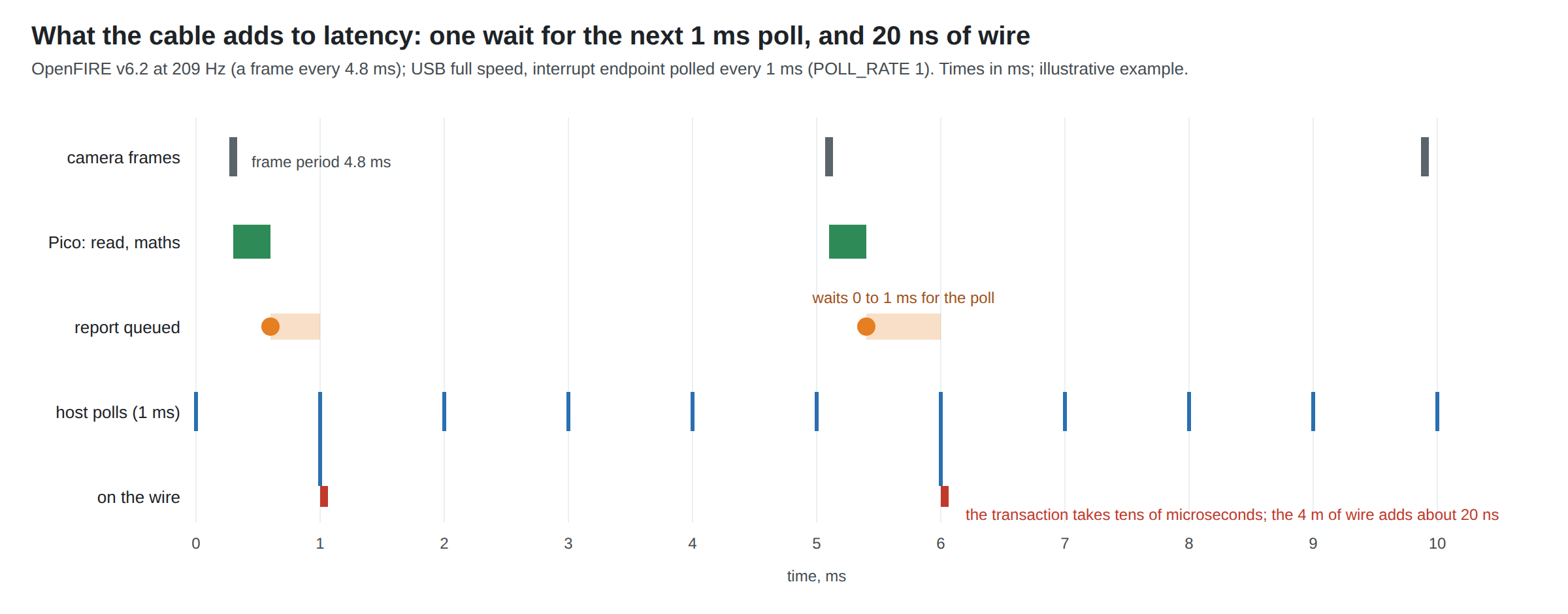
The whole latency chain from the light changing to the picture changing is worked through in Aiming Maths and Calibration Vol 7, 7.5: the gun’s own share is about 2.7 to 8.8 ms (5.6 ms on average with Average smoothing), and the game and the television dominate the rest. What belongs to the wired architecture specifically is three terms:
Table 4 — The whole latency chain from the light changing to the picture changing is worked through in [Aiming Maths and Calibration Vol 7, 7.5](/light-guns/sensing-and-aiming/aiming-maths-and-calibration/vol-7/): the gun's own share is about 2.7 to 8.8 ms (5.6 ms on average with Average smoothing), and the game and the television dominate the rest. What belongs to the wired architecture specifically is three terms
| Term | Size | Note |
|---|---|---|
| Propagation down the cable | about 20 ns for 4 m | At 5 ns per metre. Negligible by five orders of magnitude. |
| Waiting for the host’s poll | 0 to 1 ms, 0.5 ms on average | OpenFIRE’s interrupt endpoints request a 1 ms interval (POLL_RATE 1); 1 ms is the shortest full speed allows (§5.7.4: 1 to 255 ms) |
| The transaction | tens of microseconds | A few bytes at 12 Mbit/s plus token, handshake and bit stuffing |
So the wired link’s contribution is about half a millisecond on average and at most one, uniformly distributed and uncorrelated with anything the player does. It is already counted in the Aiming Maths chain as its “USB report waiting for the host’s poll” row, and it is the floor any other architecture is measured against: a radio link adds its own air-time, retry and dongle-to-host poll on top (Fully Wireless; Open-Source Firmware Vol 6, 6.12 on the D25 trial’s questions).
The recoil path. By default the gun fires its own solenoid when the trigger is pulled, so the cable adds nothing to the kick’s timing. When the game drives feedback instead (force-feedback commands from a hook program over the serial interface; Open-Source Firmware), the command crosses the same USB link in the other direction, with the same 0 to 1 ms frame granularity plus whatever the host software adds. The 24 V supply is already at the gun: no part of the power path is in the timing.
5.8 Measuring It
All with the lab’s Analog Discovery Pro ADP3450, following the ground-loop precautions of Power Supplies Vol 5, 5.10 (gun and instrument on the same PC):
- Ground offset during firing (W6 in Vol 6). Gun ground and the PC’s USB shell, two channels subtracted. Expected tens of millivolts, unchanged by the coil. Volts mean the return is shared somewhere.
- Packet integrity under autofire (W7). The logic analyser’s USB decoder on D+ and D− at a breakout near the PC, a few minutes of autofire, counting retries and resets; or simply the host’s own log of device disconnects.
- The gun’s share of latency, as Aiming Maths Vol 7, 7.6 describes, once with the 4 m umbilical and once with a 0.5 m USB lead straight to the Pico. The two histograms should be indistinguishable. If they are not, something other than the wire is responsible.
5.9 What Could Not Be Verified
- The 25 mm untwisted limit is an engineering margin derived here from the 13 cm lumped-element boundary, not a figure from the USB specification.
- The 4 m cable’s real impedance and delay are the 28/24 cable maker’s, unmeasured; a NanoVNA on the lab bench can measure both (time-domain mode, open-ended pair).
- The coupling from the 24 V pair into the USB pair has not been measured; the expectation of no effect rests on the separate return and the twisted pair (W7).
- Host-side latency after the poll (operating system and game input handling) is outside this dive and was not measured.
Footnotes
-
USB Implementers Forum, Universal Serial Bus Specification Revision 2.0 (
usb_20.pdfinusb_20_20250603.zip), sections as cited in the tables. https://www.usb.org/document-library/usb-20-specification (downloaded 2026-10-19). ↩
Comments (0)