Controls and Inputs · Volume 5
Debounce and Timing — What the Contacts Do, What OpenFIRE Does About It, and What It Costs
OpenFIRE waits for 32 identical reads and then ignores the pin for 15 or 20 milliseconds. The lockout limits the repeat rate, not the latency; the 32-read filter is the delay, and nobody has measured how long it takes in run mode. A Hall trigger can skip both
5.1 How Long Contacts Bounce
The best open measurement of switch bounce is Jack Ganssle’s A Guide to Debouncing (2004, revised 2014). He put eighteen different switches on a scope. Sixteen of them “exhibited an average 1557 µsec of bouncing”, with a maximum of about 6,200 µs; the two outliers were far worse, one taking 157 ms to settle on opening. His conclusion in the second part is that “Most switches seem to exhibit under 10 msec bounce rates”, and he designs for 20 ms “to be conservative”.
The one datasheet figure among the parts in Volume 3 agrees: the Omron B3F tact switch’s sheet gives “Bounce time 5 ms max.” None of the snap-action switch datasheets read gives a bounce time (Volume 3, §3.3).
Bounce is worse at the opening edge in several of Ganssle’s switches, and it varies from one actuation to the next. A debounce scheme therefore has to handle a few milliseconds routinely, tolerate the occasional ten, and treat anything far longer as a worn or contaminated switch.
5.2 What OpenFIRE Does, From the Source
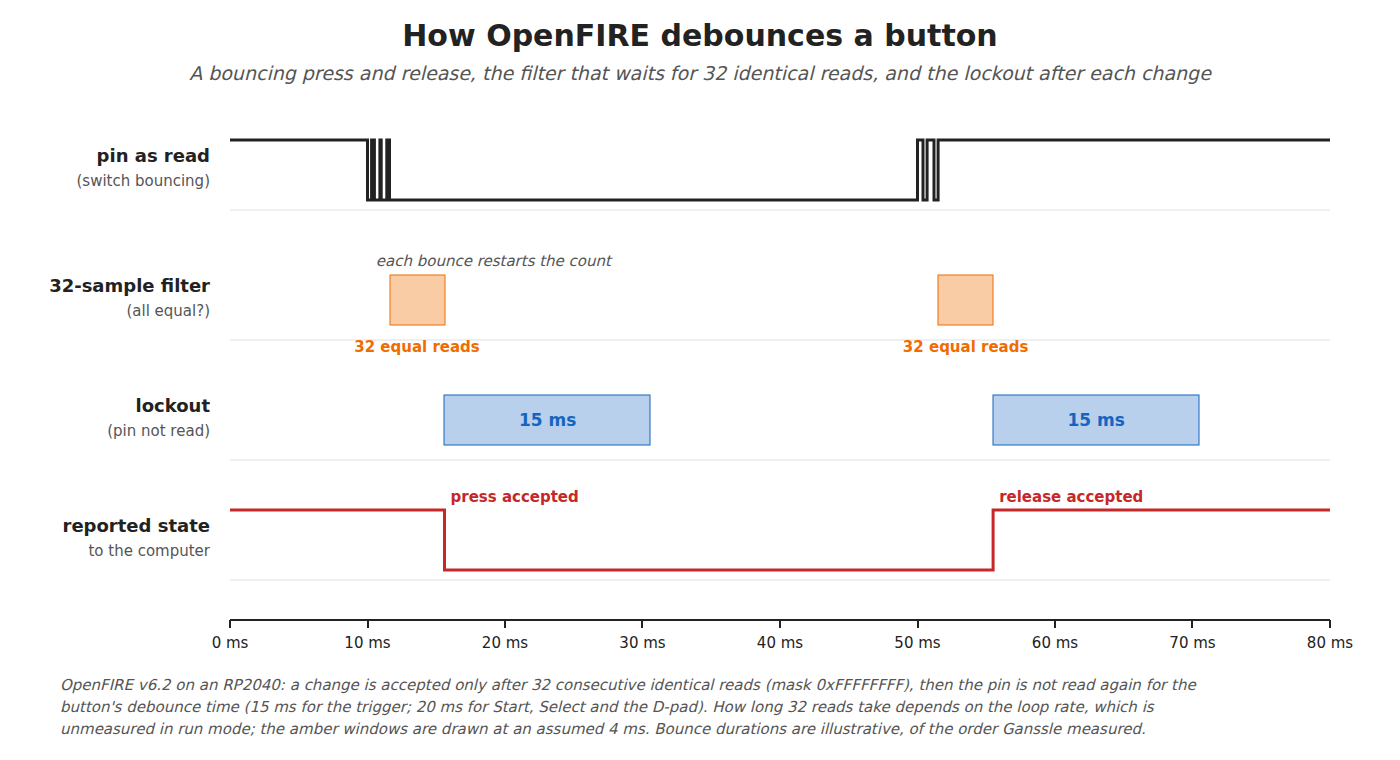
The button library (libraries/LightgunButtons/LightgunButtons.cpp, OpenFIRE v6.2) runs two mechanisms in its Poll() function. Read line by line:
- A lockout counter. If a button has a non-zero
debounceCount, the elapsed milliseconds since the last poll are subtracted from it, and the pin is not read at all until it reaches zero. - A sample filter. When the pin is read, the reading is shifted into a 32-bit history (
stateFifo). The masked history must be all ones or all zeros for the reading to count; anything else is treated as “bouncing, continue to next button”. - On an accepted change, the button’s state is updated, the press or release is reported, and the lockout counter is loaded with that button’s
debounceTicks. This happens on the release as well as on the press.
The constants, from the descriptor table in OpenFIREprefs.h and the board flags in OpenFIREBoard.h:
Table 1 — The constants, from the descriptor table in OpenFIREprefs.h and the board flags in OpenFIREBoard.h
| Button | Debounce time (lockout) | Filter mask on RP2040 |
|---|---|---|
| Trigger | 15 ms | BTN_AG_MASK = 0xFFFFFFFF (32 reads) |
| A, B, C | 15 ms | BTN_AG_MASK2 = 0xFFFFFFFF |
| Start, Select | 20 ms | 0xFFFFFFFF |
| D-pad, all four | 20 ms | 0xFFFFFFFF |
| Pedal, Alt Pedal, Pump, Home | 15 ms | 0xFFFFFFFF |
The ESP32 port uses the same table and the same masks (its OpenFIREBoard.h applies them to RP2040 and ESP32 alike), and adds an inversion mask so that normally-closed switches can be used.
A design choice worth noticing. The predecessor firmware, Mike Lynch’s SAMCO Prow Enhanced, set different filter lengths for the trigger and the other buttons on some chips: on the SAMD21, 10 reads for the trigger (0x3FF) against 12 for the rest (0xFFF); on the ATmega32U4, 2 against 4. The trigger was given the shorter filter, which is to say less delay. On the RP2040 both are 32, so OpenFIRE gives the trigger no such preference. Its trigger lockout is also 15 ms where Prow’s was 20.
5.3 A Correction to a Published Volume
Reference Electronics, Volume 4, §4.3 says the lockout “is 15 for every button in the default descriptor table in OpenFIREprefs.h”. The table gives 20 ms for Start, Select and the four D-pad directions and 15 ms for the rest. Open-Source Firmware, Volume 6, §6.3 already prints the right figures. The difference changes nothing in Reference Electronics’ design conclusion, since both values are far longer than ordinary bounce; it is reported to the controlling session rather than edited here.
5.4 What It Costs in Latency
The two mechanisms cost different things.
The lockout is not latency. It starts after a change has been accepted and reported. What it limits is how soon the next change can be seen: a press locks the input for 15 ms, then a release locks it for another 15 ms. A full press-release cycle of the trigger cannot complete in less than about 30 ms plus two filter windows, a ceiling of roughly 30 pulls a second. No finger approaches that, but autofire is not a finger, which is why OpenFIRE’s autofire timing lives in the solenoid code and not here (Open-Source Firmware, Volume 5).
The filter is the latency. A press is reported only after 32 consecutive identical reads, counted from the last bounce. So the delay from the finger to the report is the bounce time plus 32 reads. How long 32 reads take depends on where the firmware is:
- In the menu and calibration paths the firmware calls
Poll(1), which reads at most once per millisecond. There, 32 reads take at least 32 ms. - In the run-mode loop on the second core it calls
Poll(0), which reads on every pass of the loop. There, 32 reads take 32 loop passes, and the loop rate in run mode has not been measured by anyone whose work was found (Reference Electronics, Volume 4 leaves the same slot). A loop of 100 µs would make the filter 3.2 ms; a loop of 1 ms would make it 32 ms.
That second number is the single most important unknown in this volume. The camera, the homography and the USB reports share the loop (Open-Source Firmware, Volume 2), so the filter’s length in time is a by-product of everything else the firmware does, not a design choice. A filter defined in reads rather than in time also changes length whenever the loop’s workload changes, for instance between the stopgap camera and the PixArt camera.
The Aiming Maths and Calibration dive’s latency chain puts the trigger alongside the camera and the display; the measurement in 5.9 is the input this volume owes to that chain.
5.5 Hardware Debounce
The classic hardware debouncer is an RC network ahead of a Schmitt-trigger input. Ganssle’s guidance is to size the RC for about 20 ms and to “use a device with Schmitt Trigger inputs”; his warning, “Never run the cap directly to the input on a microprocessor”, is about inputs without hysteresis. The RP2040’s pads have a Schmitt trigger enabled by default (the SCHMITT bit in each pad control register resets to 1, RP2040 datasheet), so a capacitor at the pin is safe on this chip.
Reference Electronics, Volume 4 draws an optional 1 kΩ series resistor and 10 nF capacitor on each button. Worked through, that network is not a bounce filter and was not presented as one:
Table 2 — [Reference Electronics, Volume 4](/light-guns/building-the-electronics/reference-electronics/vol-4/) draws an optional 1 kΩ series resistor and 10 nF capacitor on each button. Worked through, that network is not a bounce filter and was not presented as one
| Pull-up | Release time constant (pull-up × 10 nF) | Press time constant | Against bounce of about 1.5 ms |
|---|---|---|---|
| Internal, 50–80 kΩ | 0.5–0.8 ms | about 10 µs | shortens nothing much; the firmware still does the work |
| External 3.3 kΩ (proposed in Volume 3, §3.4) | 33 µs | under 10 µs | none |
What it does do is reject spikes of microseconds, the kind a solenoid’s switching edge can couple into a long lead, which is the role Reference Electronics gives it. With the stronger pull-up proposed in Volume 3 the release edge becomes sharper still, which is no loss: the firmware’s filter handles bounce either way.
A true hardware debouncer is not worth fitting here. A 20 ms RC would add up to 20 ms of delay on top of a firmware filter that cannot be turned off without forking, buying nothing. The one case where hardware filtering earns its place is a long lead (5.7).
Interrupts. Ganssle’s other rule is “don’t tie undebounced switches … to interrupt inputs on the CPU”, and to read them in a timer-driven routine instead. OpenFIRE polls; a fork should keep it that way for buttons.
5.6 The Hall Trigger Needs None of It
The trigger is a Hall sensor (D8). Read through the ADC in the fork (Reference Electronics, Volume 4, §4.6), it has no contacts and therefore no bounce. Its noise is a few millivolts, and the press and release thresholds are about 150 ADC counts apart against about 4 counts of noise. That hysteresis is the debounce.
So the fork’s trigger path should bypass the button library’s filter and lockout: compare each ADC reading with the thresholds and report a change at once. That removes the 32-read delay from the one input where delay matters most, and makes the Hall trigger faster than a microswitch trigger under stock firmware, not merely more durable. This is proposed as row CI-6 for Our Firmware.
With stock firmware and the digital DRV5023 in the same footprint, the sensor’s output is an open-drain switch to ground with built-in hysteresis; it does not bounce either, but it goes through the button library like any switch and pays the same filter delay.
5.7 Long Leads: the Pedal
A foot pedal sits at the end of a metre or more of cable, which is an antenna lying on the floor. The two hazards are induced spikes (from the solenoid’s own cable, which runs alongside it into the gun) and electrostatic discharge from a foot or a carpet. The firmware filter’s 32 identical reads reject a short spike; ESD is a different matter. Fitting Reference Electronics’ optional RC on the pedal input, and a TVS at the jack, is cheap insurance; the circuit is Reference Electronics’ to draw (Volume 4, §4.8 puts the pedal on its own JST PH lead to a panel jack). Volume 6 covers the pedal itself.
5.8 How Much Delay a Player Notices
Ganssle, informally, from his own testing: “a 100 msec delay is quite noticeable”, while “50 msec, though, seemed instantaneous”. That is a rule of thumb for a button with no other feedback, not a light-gun figure; in a light gun the trigger’s delay adds to the camera’s, the firmware’s and the display’s, and the total is what the player feels. The Aiming Maths and Calibration, Volume 7 latency chain is where that total is added up. The button path’s share should be a few milliseconds, which is achievable for the trigger by 5.6 and must be measured for the rest by 5.9.
5.9 Measuring It
Two captures settle the open questions in this volume, both on the ADP3450 (decision D9).
5.10 Why This, and Why Not the Others
Table 3 — 5.10 Why This, and Why Not the Others
| Choice | Picked | Rejected, and why |
|---|---|---|
| Debounce for buttons | Stock firmware: 32-read filter plus 15/20 ms lockout | A hardware 20 ms RC: adds delay on top of a filter that remains. A shorter firmware filter: a fork change worth making only after 5.9 measures the loop |
| Debounce for the trigger | None: the fork reads the ADC with threshold hysteresis and bypasses the filter (CI-6) | Running the analog trigger through the button library: pays the 32-read delay for a sensor that cannot bounce |
| RC on each input | Optional 1 kΩ / 10 nF (Reference Electronics), fitted on the pedal | Fitted everywhere: harmless but unnecessary on short leads |
| Reading method | Polling | Interrupts: Ganssle’s rule; no gain at these rates |
5.11 What Could Not Be Verified
- The run-mode loop rate, and therefore the filter’s real length in milliseconds.
- Bounce times for the D2F-01F and the SKRHABE010; their datasheets give none.
- Whether the lockout’s 30 ms cycle ceiling ever bites in a real game (it should not for a finger).
Sources
- TeamOpenFIRE, OpenFIRE-Firmware v6.2 (dev branch):
libraries/LightgunButtons/LightgunButtons.cpp(Poll()),OpenFIREmain/OpenFIREprefs.h(descriptor table, lines 207–223),libraries/OpenFIREPosition/OpenFIREBoard.h(masks),OpenFIREmain/OpenFIREmain.ino(Poll(1)andPoll(0)call sites). https://github.com/TeamOpenFIRE/OpenFIRE-Firmware (read 2026-10-19). - Alessandro Satanassi, OpenFIRE-Firmware-ESP32,
lightgun/lib/OpenFIREPosition/OpenFIREBoard.handlightgun/lib/LightgunButtons/LightgunButtons.cpp(inversion mask) (read 2026-10-19). - Mike Lynch (Prow7), ir-light-gun (SAMCO Prow Enhanced), https://github.com/Prow7/ir-light-gun,
libraries/SamcoPositionEnhanced/SamcoBoard.handSamcoEnhanced/SamcoEnhanced.ino(read 2026-10-19). - Jack Ganssle, A Guide to Debouncing, parts 1 and 2, The Ganssle Group, 2004, rev. 4 2014. https://www.ganssle.com/debouncing.htm and https://www.ganssle.com/debouncing-pt2.htm (read 2026-10-19).
- Omron, B3F Tactile Switch datasheet, “Bounce time 5 ms max.” (read 2026-10-19).
- Raspberry Pi Ltd, RP2040 Datasheet, pad control registers (
SCHMITTreset value 1) and GPIO electrical characteristics. Central Library (read 2026-10-19).
Comments (0)