Ruger 10/22 · Volume 2
How It Works — Blowback, the V-Block, the Rotary Magazine and the Decelerator
The full cycle of operation, part by part, from Ruger's manuals and the 1964 patents
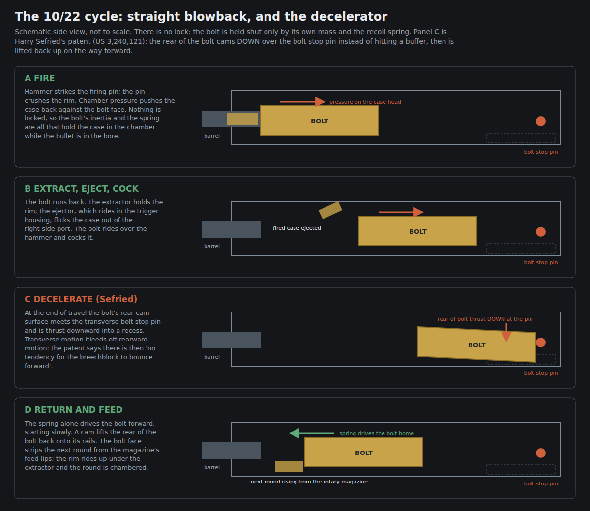
This is the mechanism volume. It follows a cartridge from the magazine to the ejection port and names every part that touches it, and it explains the four features that make the 10/22 behave the way it does: an unlocked bolt, a cam at the back of the receiver, a magazine that presents every round at the same angle, and a barrel held by a clamp. Volume 7 covers taking it apart and keeping it running; this volume is what Volume 7 assumes.
The sources throughout are Ruger’s two current manuals — PM058, for rifles made before model number 32000, which is what both rifles in Volume 8 are, and PM1269, for model 32000 and later — the 1964 American Rifleman test report, and the two Sefried patents.12345
2.1 What Kind of Action This Is
Ruger’s manual opens its mechanical description by calling the 10/22 an “autoloading, recoil operated rifle.”1 Twenty-two pages later, in the section on cleaning, the same manual calls it “this blow-back operated autoloading firearm.”1
The second phrase is the precise one. In a recoil-operated firearm in the strict sense the barrel moves; in the 10/22 the barrel is clamped to the receiver and never moves. What happens is straight blowback: the bolt is not locked to anything. When the cartridge fires, pressure in the case pushes the case head back against the bolt face, and the only things resisting are the inertia of the bolt and the force of the recoil spring. The .22 Long Rifle’s pressure and case-head area are small enough that a bolt of practical weight, with a light spring, holds the case in the chamber long enough for the bullet to leave and pressure to fall, and then the bolt is driven back to cycle the action. Ruger’s manual describes the result without the vocabulary: “the same gas pressure that drives the bullet forward also acts through the cartridge case to push the bolt to the rear. That action causes extraction and ejection of the fired cartridge case.”2
Three practical consequences follow from blowback and recur throughout these volumes:
- Bolt mass and spring rate are the tuning variables. There is no gas port or lock timing to adjust. Aftermarket bolts, springs and buffers work by changing mass, spring force or the end-of-travel behaviour, and nothing else. (Volume 4; for the effect on subsonic ammunition, the .22 Rimfire dive’s Volume 9.)
- The chamber must be clean. An unlocked bolt extracts on residual pressure. Ruger: “Cleanliness is most important to the function of this blow-back operated autoloading firearm. Any failures to feed or extract rounds may be indications of a dirty chamber.”1
- The fouling goes into the action. With no lock and no seal, combustion residue blows back around the case into the receiver. On a suppressed rifle the volume of gas going backward rises. (Volume 7.)
2.2 The Parts, by Group
A 10/22 separates into five groups. The names are Ruger’s, from the parts lists in its manuals.12
Table 1 — 2.2 The Parts, by Group
| Group | Parts (Ruger’s names) | How it is attached |
|---|---|---|
| Receiver | Receiver; receiver filler screws (4); on model 32000 and later, a cleanout hole plug | — the serial-numbered part |
| Barrel | Barrel; barrel retainer V-block; barrel retainer screws (2); sights | V-block and two screws |
| Bolt group | Bolt; firing pin; firing pin rebound spring; firing pin stop (or retention) pin; extractor; extractor spring; extractor plunger. Separately: the cocking handle, guide rod and recoil spring assembly | Lies in the receiver; the bolt clips onto the cocking handle; retained by the bolt stop pin |
| Trigger housing | Trigger guard; bolt lock and spring; hammer, hammer pivot pin, strut, spring and washer; ejector; safety, safety detent plunger and spring; disconnector; sear and sear spring; trigger, trigger pivot pin, trigger plunger and spring; magazine latch, pivot pins, plunger and spring | Two receiver cross pins |
| Stock | Stock; buttplate or recoil pad; barrel band (carbine); takedown screw | Takedown screw into the bottom of the receiver; barrel band at the front on carbines |
The bolt stop pin belongs to none of these groups on its own. It is a transverse pin through the rear of the receiver, and it is held in place, like the two receiver cross pins, by the stock around it — which is why Ruger warns, when lifting the action out, to “be careful the two receiver cross pins and bolt stop pin do not fall out.”1 Section 2.4 explains why it is the most interesting part in the rifle.
2.3 The Cycle, Step by Step
Ruger’s own description of the cycle, from the manual, is the baseline:1
Retracting the cocking handle cocks the internal hammer and compresses the recoil spring. When the bolt is manually released, it moves forward (driven by the recoil spring), strips a cartridge from the magazine, if a loaded magazine is in place, and chambers the cartridge. The bolt is held against the chambered cartridge by the recoil spring.
When the trigger is pulled, the hammer is released and strikes the firing pin. The firing pin indents the cartridge case rim and ignites the priming compound inside the rim. … The bolt then moves rearward automatically, extracting and ejecting the fired cartridge case, and at the same time cocking the hammer and compressing the recoil spring … Once the trigger is released, the rifle is ready to fire again.
Expanded, part by part:
- Loading. The shooter draws the cocking handle back. The handle is not part of the bolt: it rides on its own guide rod with the recoil spring around it, in a pocket on the right side of the receiver, and a recess in the top of the bolt clips over it (Ruger’s reassembly instruction is to “lay the recessed section of the top of the bolt on the section of the cocking handle that mates with it” and press “until a ‘click’ is heard”).1 Pulling the handle drags the bolt back, compresses the spring, and lets the bolt override the hammer and cock it.
- Feeding. Released, the spring drives handle and bolt forward. The bottom of the bolt face meets the rim of the top cartridge, which the magazine is holding against its feed lips. The bolt pushes the round forward out of the lips; as the round moves, its rim rides up ramps at the rear of the magazine’s feed gate “into the cartridge head recess of the breech block and under the extractor,” and its nose, which the magazine already holds tilted slightly upward, enters the chamber.4 Section 2.5 explains why no feed ramp is needed on the barrel.
- Chambering. The round seats; the extractor’s spring-loaded hook snaps over the rim; the bolt comes to rest against the barrel’s breech face, held there only by the spring.
- Firing. The trigger releases the sear; the sear releases the hammer; the hammer, driven by its spring on a strut, strikes the rear of the firing pin; the pin crushes the rim against the breech face and fires the priming compound in the rim.
- Blowback. Pressure pushes the case back against the bolt face. The bolt, unlocked, begins to move once its inertia and the spring are overcome, dragging the case with it on the extractor.
- Extraction and ejection. As the bolt travels back, the base of the case meets the ejector — which projects up into the bolt’s path from the trigger housing — and is pivoted out of the ejection port on the right (Section 2.6).
- Cocking. The bolt passes over the hammer and pushes it down into the housing, where the sear catches it. The disconnector keeps the hammer from following the bolt forward while the trigger is still held back; releasing the trigger resets it. That is what makes the rifle semi-automatic: one shot per pull.
- Deceleration. Near the end of its travel the bolt meets the bolt stop pin. It does not simply hit it (Section 2.4).
- Return. The spring drives the bolt forward again and the cycle repeats from step 2. After the last round the bolt closes on an empty chamber. The rifle does not lock open on an empty magazine. Ruger: “The bolt does not remain open after the last shot has been fired, nor does the bolt automatically lock open when the magazine is empty.”1 (Ruger’s newest parts list does include a part named “Last Round Spring” in the bolt assembly of model 32000 and later rifles; the manual does not describe its function, and no last-round hold-open is claimed for any rifle here.2)
2.4 The Decelerator
The 10/22’s bolt is fast. A blowback bolt returning at full speed could close before a lightly sprung magazine had lifted the next cartridge into place, and a bolt that slams into a hard stop tends to rebound forward, adding speed to the return stroke. Harry Sefried’s patent states the problem in one sentence: “The breechblock of an automatic blow back gun can go rearward and return at such a rate as to fire too rapidly, or it may be too rapid for the reliable feeding of cartridges from the magazine into the barrel chamber.”5
His solution adds no parts. The rear of the bolt carries a curved cam surface. The receiver carries a transverse pin — the bolt stop pin. As the bolt nears the end of its travel, the cam meets the pin and the pin’s round surface drives the tail of the bolt downward, into a clearance recess below the rails. In the patent’s preferred embodiment the pin is “for example, of 0.250 inch” diameter, and the bolt’s cam is two radii — 0.1562 in and 0.109 in — and a flat, with “the radius of the pin … smaller than the radius of R but larger than the radius of R′.”5 Rearward momentum is converted into downward motion, and the bolt stops.
Then, on the way forward, a second pair of cam surfaces, on the receiver rails ahead of the rear, lifts the tail of the bolt back up onto its rails.
What the patent claims for this is specific, and it is the most important paragraph in this volume for anyone about to buy a “bolt buffer”:
There is no tendency for the breechblock to bounce forward (at the completion of its rearward movement) as there would be if the breechblock were stopped by a resilient buffer or by striking against a fixed stop member while traveling at the velocity typical in self loading firearms mechanisms. By eliminating the bounce effect the present invention secures the advantage of having the breechblock move forward under the influence of the return spring only. Accordingly, the breechblock will begin its forward stroke with a gradually accelerated motion, the cyclic rate of the firearm will be reduced, and reliability of feed will be increased when spring-actuated magazines are used because the reduced forward velocity of the breechblock gives the magazine more time in which to position the next cartridge for insertion into the firing chamber.5
The patent closes: “The retardation is sufficient to permit reliable feeding of cartridges from magazines having a relatively slow rate of feed of the cartridges to loading position such as rotary magazines.”5 Kuleck’s history confirms the production rifle uses the idea: “The bolt stop acts as a rate reducer, giving the rotary magazine time to present the next cartridge in front of the bolt as the bolt returns to battery.”6 And the 1964 test report connects it to the magazine directly: the delay is why the rotor spring can be light, and the light rotor spring is why the magazine is easy to load.3
⚠ Two cautions about reading a patent. A patent’s preferred embodiment is not a production drawing; the pin diameter and radii are given “for example,” and no Ruger drawing of the production bolt or pin was available for this dive. And the patent’s argument is an argument from design intent, not a test result. What it establishes beyond doubt is that the bolt stop pin in a 10/22 is not a mere stop: it is one half of a cam, and anything that replaces it changes the cam. Volume 4 takes that to the aftermarket buffers.
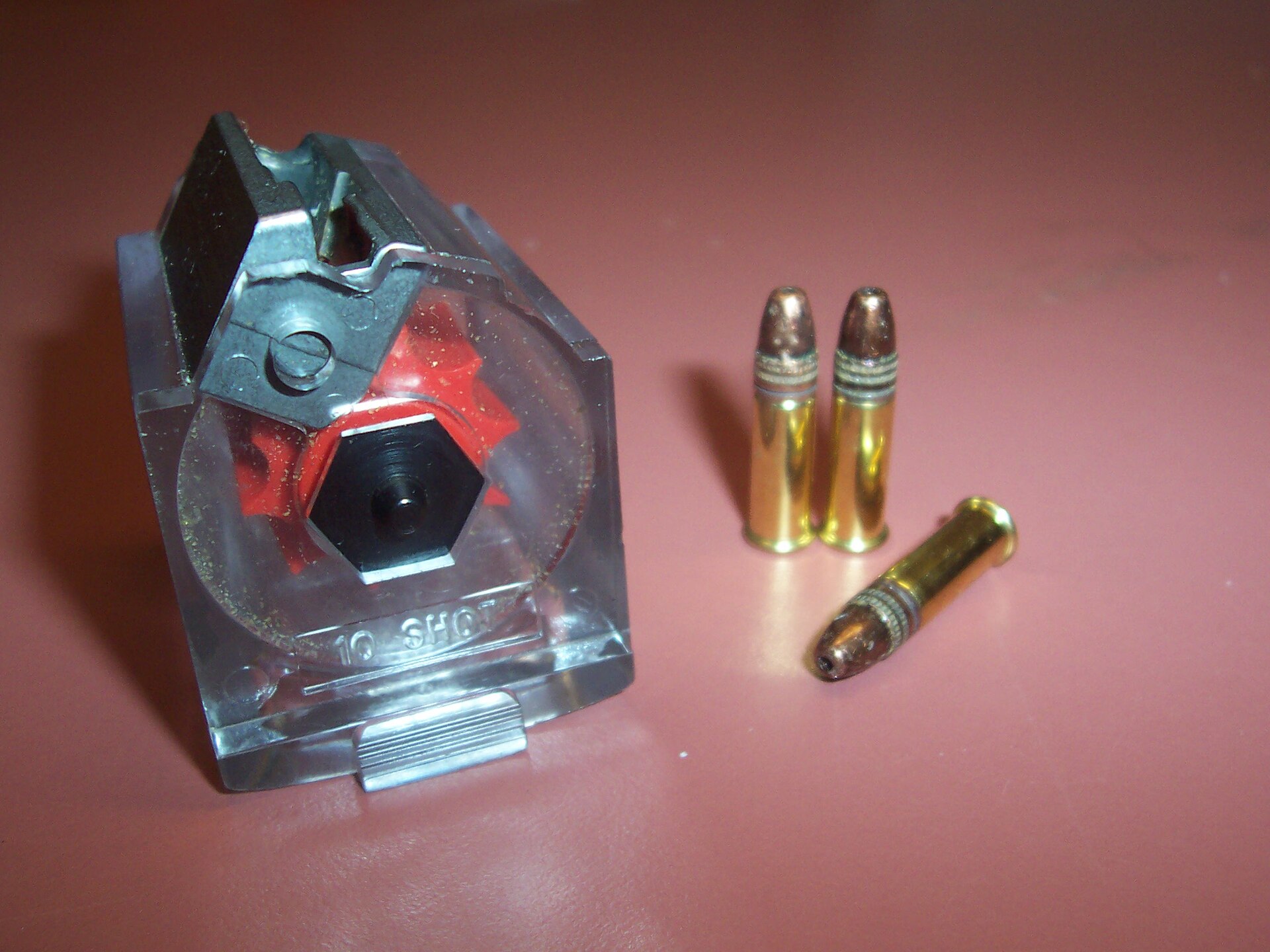
2.5 The Rotary Magazine
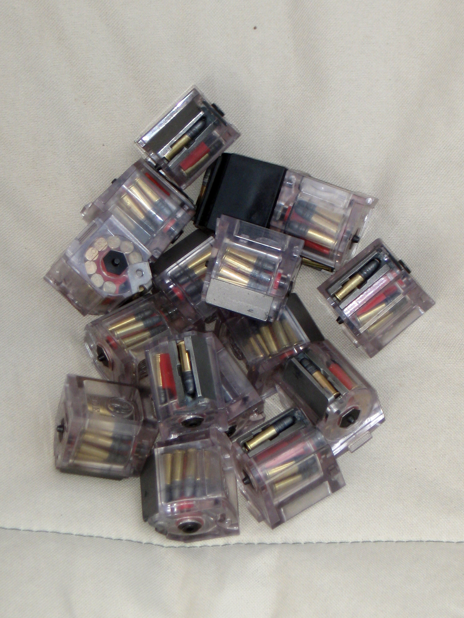
The patent for the magazine, filed by Sefried and McClenahan on 24 March 1964, describes it more precisely than any later account.4
The rotor. A rotor on a central pin carries “a plurality of peripheral cartridge pockets P and dividing ribs R.” The pockets are skewed: their axes are inclined to the rotor axis so that “the rim of one cartridge lies ahead of the rim of the next cartridge in the direction of feeding.” Two things follow, and the patent claims both. The rounds cannot interlock rims, which is the classic rimfire double-feed; and “the skewed ribs and pockets of the rotor minimize the diameter of the magazine for any given capacity by allowing the rims to overlap.”4 That second point is why ten rounds fit in a magazine that sits flush with the bottom of the stock.
The spring. A torsion spring inside the rotor, anchored at one end in the rotor and at the other in the frame, turns the rotor and holds the top cartridge against the lips. The spring is preloaded at assembly by turning the rotor against it.4 Ruger’s 2003 manual gave the factory setting in figures — “rotating the magazine cap nut until the rotor stops turning. Then the nut is turned an additional 1 1/4 turns beyond the ‘stop’ position” — and later manuals drop the figure and say only that tension “is set at the factory.”71
The gate and lips. At the top is a feed gate, which the patent recommends be “a casting, preferably of metal.” The 1964 test found exactly that: a plastic body with a “magazine throat [that] is a steel investment casting.”43 The lips are offset from the bore axis to ease the rim into the bolt’s recess.
The last round. One rib of the rotor is extended into a finger that “cams the last cartridge against the baffle on the gate and elevates it into position for entry into the chamber” — the rotor has run out of neighbouring cartridges to push against, so the finger does the job.4
The magazine is the feed ramp. Because the pockets are skewed, the patent notes, the top cartridge “will have its bullet end somewhat elevated toward the mouth of the chamber, thus eliminating the need for a long guide ramp on the barrel.”4 Kuleck’s caption on the patent drawing says the same: “the magazine serves as the feed ramp.”6 This has a practical consequence for feeding problems: a damaged lip or a burr on the gate is a damaged feed ramp, which is why Ruger’s malfunction checklist says to “check the magazine throat … free of nicks and burrs and … not deformed.”1
How it is held. The magazine has no side walls in the receiver to locate it. The central pin projects from both ends of the magazine; its front end enters a bore in the receiver’s forward wall “in which it makes a close fit,” and its rear engages the spring-loaded latch, which “snaps forward to lock the magazine in position.”4 The magazine’s own pin, not its body, is what aligns it to the bolt.
Ruger on care. Ruger’s current instruction is unambiguous: “Do not disassemble the magazine. Improper reassembly or improper tensioning of the rotor spring can cause a potentially dangerous malfunction. If you experience a problem with the magazine, don’t use it. Get a new one.”2 That reverses the 1964 direction sheet, which told owners to strip the magazine “after firing 500 rounds or so” and explained how to retension the rotor spring.3 The tension test Ruger does publish is simple and worth doing on every magazine: load one round, press firmly on the top of the case, release quickly — “The cartridge should instantly and fully move in to the feeding position.”2
2.6 Extraction and Ejection
The extractor is in the bolt: a hook on the right side of the bolt face, held against the rim by the extractor spring through the extractor plunger.1 It holds the case to the bolt face during extraction. It is small, its hook takes all of the extraction load, and it is the part the aftermarket replaces most often after the bolt lock (Volume 4). Ruger’s cleaning instruction names it specifically: “Thoroughly clean the chamber and the extractor as often as necessary to prevent the accumulation of grease and dirt.”1
The ejector is not in the bolt. It is a part of the trigger housing, pivoting on a pin and projecting upward into a slot in the receiver so that it lies in the path of the case head as the bolt comes back.12 The consequence for reassembly is written into Ruger’s instructions twice: “Be sure the ejector is held in the ejector slot as you set the trigger guard in place.”1 An ejector that is not in its slot means a rifle that will not throw its cases.
Ruger also documents the failure a blowback rifle is most prone to when worked by hand: “when the bolt is operated by hand, there can be a failure to extract the cartridge from the chamber, or a failure to eject the cartridge clear of the rifle. These failures usually are the result of the bolt not being pulled rearward vigorously, coupled with an accumulation of fouling in the chamber.” The extracted round “can be ‘ejected’ into the magazine area, instead of outside the rifle” — and if an empty magazine is fitted, it may land on the magazine and be rechambered when the bolt closes.2 Unloading is therefore magazine first, then bolt, then a look.
2.7 The Trigger Housing
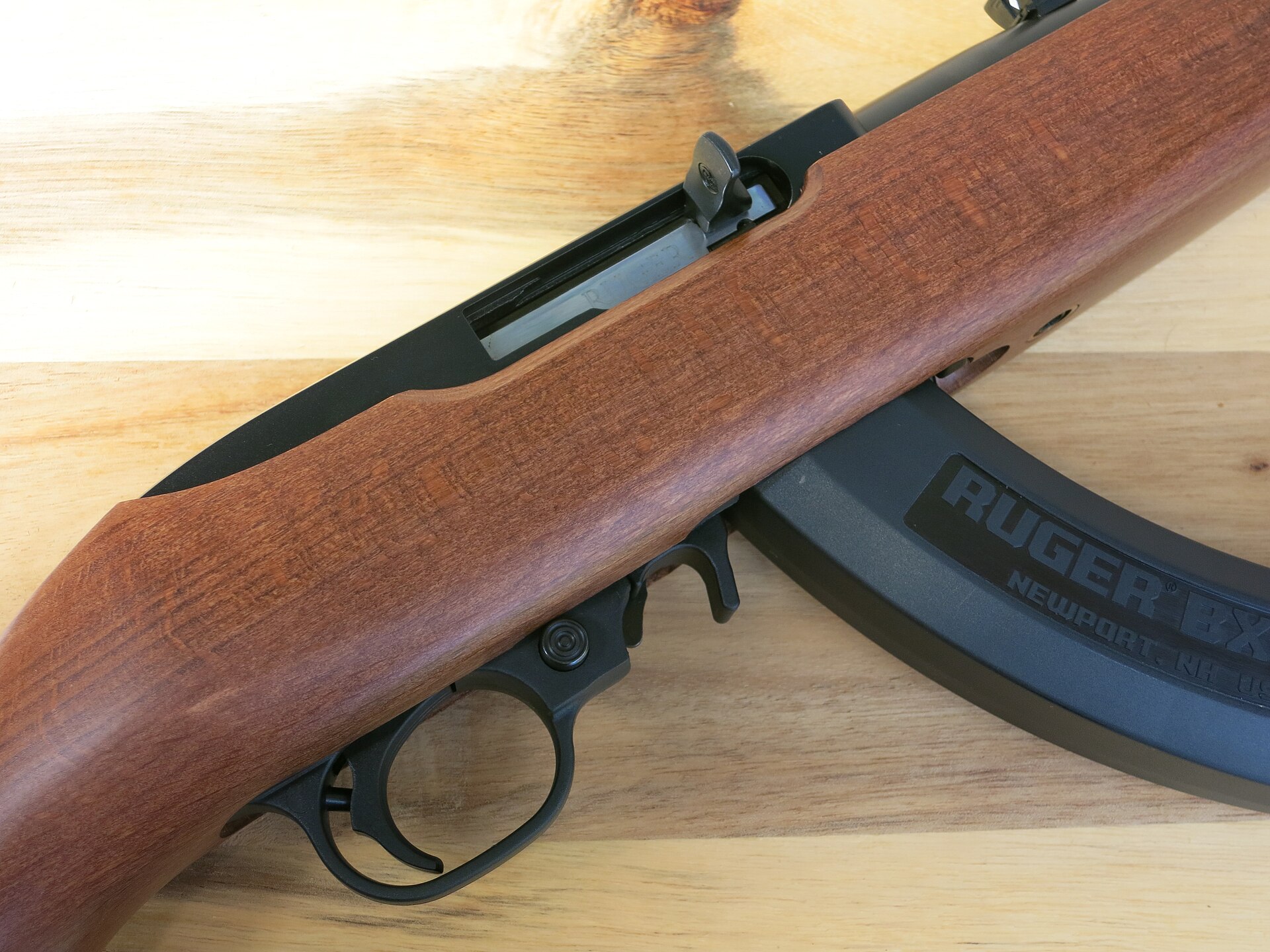
Kuleck traces the lockwork to the Winchester Model 1905, via the .44 carbine, “albeit with two transverse pins retaining the trigger assembly to the receiver.”6 Inside the housing, on the parts list: hammer, hammer strut and spring; sear and sear spring; trigger and trigger plunger; disconnector; the cross-bolt safety and its detent; the bolt lock and its spring; the ejector; and the magazine latch.1
- The safety is a cross-button in the front of the trigger guard. Pushed to the right side (the cocking-handle side) it is on, and “the sear is blocked.” Pushed left it is off and shows a red band. It “can be operated only when the hammer is cocked.” It is held in each position by a spring-loaded detent, and “a distinct ‘click’ should be heard”; if it is not, Ruger says to stop using the rifle and send it in.1
- Factory-fit parts. Ruger marks certain fire-control parts as factory-fit only, fitted “on an exchange basis.” In the current manual those are the sear, hammer and trigger; on the Takedown supplemental list, the barrel-joint insert.2 This bears on repair (Volume 7).
- Trigger weight. The 1964 report measured “about 7 lbs.”3 Ruger’s BX-Trigger, now standard, is specified at 2.5 to 3 lb.8 Neither rifle in Volume 8 had a BX-Trigger fitted as of September 2026.
2.8 The Bolt Lock
The bolt lock is a small lever in the front of the trigger guard, behind the magazine release.2 Its only job is to hold the bolt open for inspection, cleaning and changing magazines. It is not a last-round hold-open (Section 2.3), and Ruger says bluntly that it is not a safety: “A slight jar to the butt end of the rifle CAN cause the bolt stop to disengage and feed a cartridge into the chamber. The bolt stop should only be relied upon to hold the bolt in its rearward position when the chamber is empty and an empty magazine is in place.”2
On every 10/22 made before model number 32000, the lock is operated by pressing on two different parts of the lever.1
- To lock open: retract the handle fully, “press in on the lower section of the bolt lock,” release the handle. It moves forward a fraction of an inch and stops.
- To release: retract the handle fully, “then press in on the upper section of the bolt lock,” release.
- “NOTE: Simply retracting the bolt will not disengage the lock. The bolt lock must be deliberately pressed up while the bolt is held fully to the rear. Only then will the bolt close when released. This is designed to prevent accidental release of the bolt from its open position.”
That note is the whole story of the first aftermarket part. The release takes two hands — one on the cocking handle, one finger on a small lever inside the trigger guard — and it is designed to. Shooters who want to drop the bolt by pulling and releasing the handle, as on nearly every other self-loader, replace the lock. Ruger’s own newer rifles now do exactly that: the manual for model 32000 and later says “Retract the bolt handle to its extreme rearward position and fully release it … Retracting the bolt will disengage the bolt lock.”2 Volume 4 covers the replacements and a trap in combining them.
2.9 The V-Block
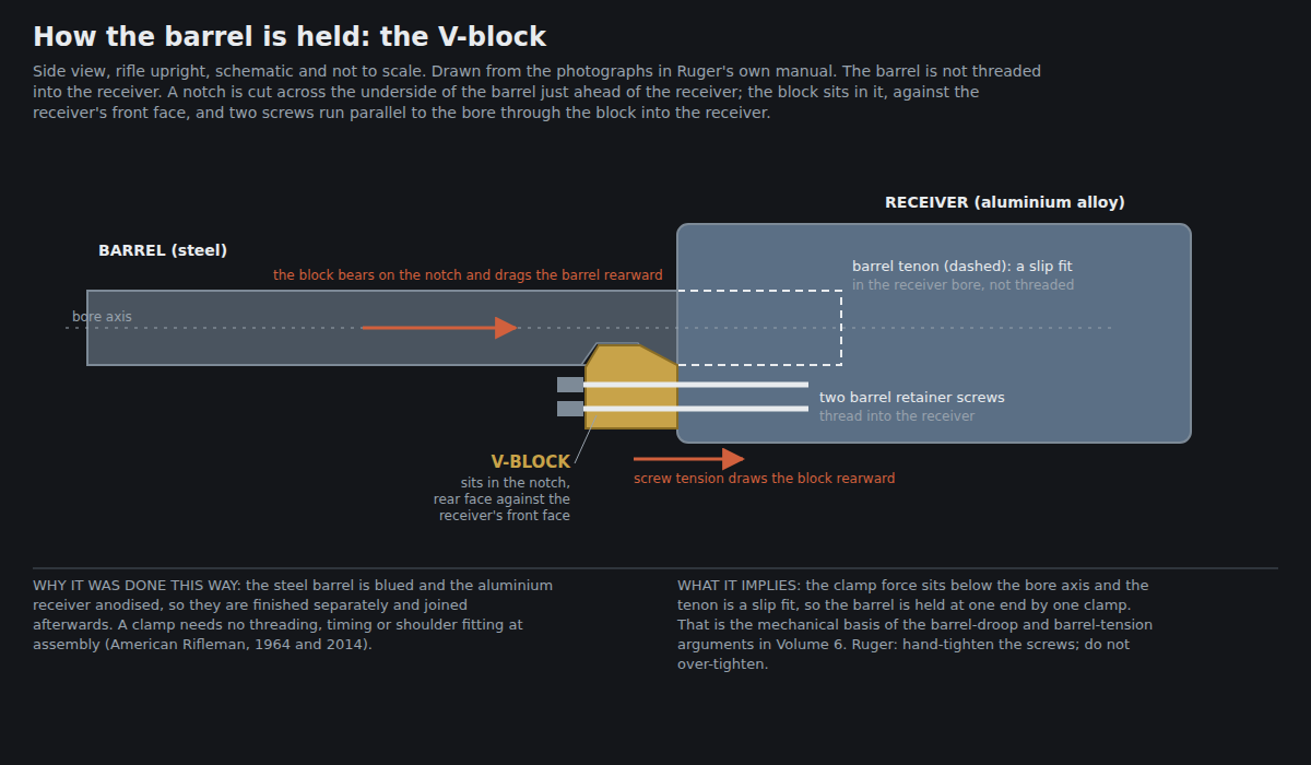
The barrel is not threaded into the receiver. The 1964 report put it exactly: “two longitudinal screws which draw the barrel up tightly against the receiver face. (The barrel tenon is not threaded into the receiver.)”3 Ruger’s current manual shows the parts: the barrel retainer V-block and two barrel retainer screws, removed with a 5/32 in hex key. To reinstall: “Insert the barrel into the receiver. Place the barrel retainer v-block into the notch in the bottom of the barrel. Insert the two barrel retainer screws through the holes in the barrel retainer v-block and into the receiver, then hand tighten them until they are securely in place. CAUTION: Do not over tighten the barrel retainer screws.”2
How it works, from those photographs: the block’s wedge-shaped edge engages the angled face of the notch. Tightening the screws draws the block rearward against the receiver’s front face, and the wedge drags the barrel rearward with it. The barrel’s position fore and aft is therefore set by where the notch is cut relative to the breech end — which is why a barrel can be changed with a hex key and no headspace gauges on the factory design (Volume 5 on what an aftermarket barrel must get right).
Two consequences are the subject of Volume 6, and are stated here so that the mechanism is complete:
- The clamp force acts below the bore axis. Both screws lie under the barrel. The barrel is held at its rear by one clamp on one side of its axis, with the tenon a slip fit in the receiver bore.
- The tenon fit is the alignment. Nothing but the fit of the tenon in the receiver bore keeps the barrel concentric and square to the receiver. KIDD’s own barrel pages attribute barrel droop to “an insecure or inconsistent tenon/shoulder fit,” and say that with a proper fit “v-block screws only need to be snug (~10 in-lb).”9 That is KIDD’s figure for its own barrels in a properly fitted receiver; Ruger publishes no torque for its screws and says only to hand-tighten.
2.10 The Stock Interface
The stock holds the action at two points on a carbine and one on a sporter. The takedown screw runs up through the stock into the bottom front of the receiver; the carbine’s barrel band clamps barrel and forend together at the front; sporter-pattern rifles, including the Deluxe Sporter, have no band.1 The 1964 report describes the bedding: “Receiver is bedded full-length in the stock. There is no recoil lug, but rear face of receiver abuts the stock mortise.”3
That last sentence is the whole recoil path: the rear face of the receiver bears against the wood or polymer behind it. For a .22 it is enough. For accuracy it means that the stock’s contact with the receiver and barrel — where it touches, how hard, and whether that changes with temperature and humidity — is part of the rifle’s zero. Volume 6 takes that up. Ruger’s own manual adds one caution in the same territory: when lifting the action out of the stock, the safety must be centred with “an equal amount of the button … exposed on each side,” or “the stock will be damaged.”1
2.11 Bibliography
Footnotes
-
Sturm, Ruger & Co., Instruction Manual for Ruger 10/22 Autoloading Rifles, PM058, B 4/2025 R40 (covering the 10/22 Takedown, Carbine, Tactical and Target LITE and earlier rifles below model 32000). General Information pp. 12–13; Operation of Safety p. 14; The Bolt Lock p. 15; firing notes p. 22; Disassembly and Reassembly pp. 28–29; Care and Cleaning p. 34; Parts List pp. 44–45. Read from Ruger’s PDF; the document is image-only and was read by optical character recognition, so part-list asterisks were checked against PM1269. ↩ ↩2 ↩3 ↩4 ↩5 ↩6 ↩7 ↩8 ↩9 ↩10 ↩11 ↩12 ↩13 ↩14 ↩15 ↩16 ↩17 ↩18 ↩19 ↩20
-
Sturm, Ruger & Co., Instruction Manual for Ruger 10/22 Autoloading Rifle, PM1269, 10/22 6/2026 R1 (“applies only to 10/22 rifles with model numbers 32000 and higher”). The Bolt Lock pp. 14–15; To Extract and Eject pp. 24–25; Minimize Malfunctions p. 26; Disassembly and Reassembly pp. 28–35; Magazine Inspection and Care p. 39; Parts List p. 50. https://ruger-docs.s3.amazonaws.com/_manuals/Ruger_1022.pdf (accessed 2026-09-19). ↩ ↩2 ↩3 ↩4 ↩5 ↩6 ↩7 ↩8 ↩9 ↩10 ↩11 ↩12 ↩13
-
NRA Technical Staff, “Ruger Model 10/22 Carbine,” The American Rifleman, September 1964, reprinted 23 October 2014. https://www.americanrifleman.org/articles/2014/10/23/throwback-thursday-ruger-model-1022-carbine-sept-1964-the-american-rifleman/ (accessed 2026-09-19). ↩ ↩2 ↩3 ↩4 ↩5 ↩6 ↩7
-
H. H. Sefried II and D. S. McClenahan, “Removable Magazine for Repeating Gun,” US Patent 3,239,959, filed 24 March 1964, granted 15 March 1966. https://patentimages.storage.googleapis.com/pdfs/US3239959.pdf (accessed 2026-09-19). ↩ ↩2 ↩3 ↩4 ↩5 ↩6 ↩7 ↩8 ↩9
-
H. H. Sefried II, “Self-Loading Guns,” US Patent 3,240,121, filed 31 August 1964, granted 15 March 1966. https://patentimages.storage.googleapis.com/pdfs/US3240121.pdf (accessed 2026-09-19). ↩ ↩2 ↩3 ↩4 ↩5
-
Walt Kuleck, “The Ruger 10/22: History & Design,” American Rifleman, 22 October 2020. https://www.americanrifleman.org/content/the-ruger-10-22-history-design/ (accessed 2026-09-19). ↩ ↩2 ↩3
-
Sturm, Ruger & Co., Instruction Manual for Blued & Stainless Steel Ruger Model 10/22 Carbine — Standard, Deluxe Sporter, International, Target and All-Weather Models, B 2/03 R11, magazine section, p. 22. Mirror: http://pdf.textfiles.com/manuals/FIREARMS/ruger_1022.pdf (accessed 2026-09-19). ↩
-
Jeremiah Knupp, “Updating A Legend: Ruger Makes 10/22 Upgrades Standard,” American Rifleman, 30 December 2025. https://www.americanrifleman.org/content/updating-a-legend-ruger-makes-10-22-upgrades-standard/ (accessed 2026-09-19). ↩
-
KIDD Innovative Design, “.22LR Lightweight Fluted Aluminum Sleeved Barrel” product page. https://www.kiddinnovativedesign.com/KIDD-22LR-Lightweight-Fluted-Aluminum-Sleeved-Barrel_p_137.html (accessed 2026-09-19). ↩
Comments (0)