MP 40 · Volume 7
Handling and Upkeep
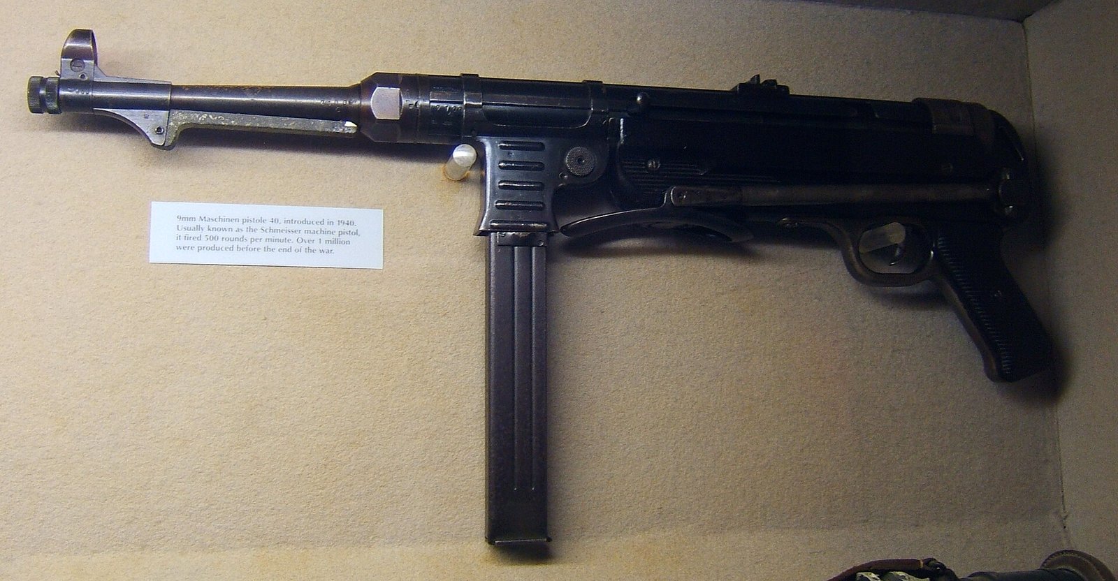
This volume covers handling a weapon that fires from an open bolt, the maintenance points that actually fail on this design, and what to inspect on a collectible example.
It begins with a limitation, stated up front rather than buried. A detailed field-strip and detailed-strip sequence would normally anchor a volume like this one. No original manual or other citable takedown source was obtained during this work, and this dive does not reproduce a disassembly sequence from memory or from uncited secondary description. Getting a step wrong in a printed procedure for a seventy-year-old open-bolt machine gun is not a small error, and a plausible-sounding sequence is worse than none.
What follows is therefore built from what these volumes have actually established: the mechanism as Volume 4 documented it, the construction as Volume 3 documented it, and the specific failure modes the sources record. Section 7.2 says what a correct procedure must account for and where to get one.
7.1 Handling an Open-Bolt Weapon
Everything about safely handling this weapon follows from one fact: when cocked, it stores a heavy bolt under spring compression, and the only thing between that and a discharge is the sear or the safety notch.
Clearing it. The order matters and it is the reverse of the habit most shooters have from closed-bolt weapons. Remove the magazine first, then retract and inspect. On a closed-bolt weapon the chamber holds the round; on an open-bolt weapon the chamber is empty when cocked and the magazine is the hazard, because any bolt movement will feed from it. A magazine left in place while the bolt is manipulated is the whole problem. With the magazine out, retract the bolt, lock it in the rear notch, and inspect the chamber and the magazine well by eye and by light.
The two safe conditions. Volume 4 set these out: bolt forward and the cocking handle lifted into the forward notch, or bolt to the rear and the handle lifted into the aft notch.1 The handle lying in the open slot is not a safe condition in either bolt position.
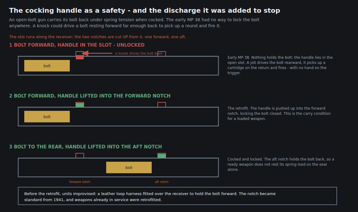
The specific hazard on an unretrofitted weapon. Volumes 1 and 4 documented it: an early MP 38 without the notch, carried bolt-forward with a loaded magazine, can fire if knocked hard enough to drive the bolt back over the top cartridge.12 Units improvised leather harnesses to hold the bolt forward before the factory fix arrived.1 Whether a given specimen has the notch is therefore a safety question and not merely a collecting detail, and § 7.5 treats it as an inspection item.
7.2 Disassembly — What a Correct Procedure Must Account For
Rather than an invented sequence, here is what any procedure a reader obtains needs to handle, drawn from the construction these volumes have documented. It is offered so that a reader can judge whether a source they find is complete.
- The weapon separates into a barrel-and-receiver group and a grip-frame group, and the two are joined by a catch and a rotational movement rather than by pins driven out. A procedure that does not describe releasing a catch and rotating one group relative to the other is not describing this weapon.
- The bolt and the telescoping recoil-spring assembly withdraw rearward from the receiver once the frame group is off. Volume 4 documented the spring assembly as a telescoping housing; a procedure must say how it is restrained during removal, because it is a spring under compression.
- The barrel and its collar are the conventionally machined assembly at the front, and their removal is a separate operation from field stripping.
- The phenolic furniture is brittle and is not a lever. Any step that involves prying against the grip frame or forearm is a step that will eventually break one.
Where to get a procedure. The original German manual for the weapon is the correct source. Failing that, an armourer familiar with the pattern, or a published reference work on the MP 38 and MP 40 specifically. This dive flags a general caution that applies with unusual force here: much online disassembly material for this weapon is filmed on semi-automatic reproductions, which are not mechanically identical to the original and whose sequences do not necessarily transfer.
7.3 Cleaning

The principles follow from the mechanism and the materials, both established in earlier volumes.
The bore and chamber are conventional. The weapon fires 9×19, a low-pressure pistol cartridge in a 251 mm barrel.3 Wartime and early post-war ammunition may be corrosively primed, and a weapon fired with it needs water-based cleaning of the bore, chamber and bolt face before oiling — a solvent alone does not remove corrosive primer salts.
The bolt face and extractor collect the most fouling, because on an open-bolt weapon they are the parts that do the chambering and the extraction and they are exposed to the open chamber between bursts.
The telescoping spring housing is the component whose whole design purpose, as Volume 4 set out, is to keep the spring enclosed and clean. That works in both directions: contamination that does get inside is correspondingly hard to reach, and a weapon that has been stored badly or fired dirty may need the assembly stripped by someone who knows it rather than flushed hopefully from outside.
The phenolic furniture. Volume 3 established what the material is: a thermosetting phenol formaldehyde resin, hard, heat-resistant and solvent-resistant, but inflexible and brittle.4 It tolerates ordinary cleaning. It does not tolerate impact, and it does not tolerate being used as a clamping surface. Aggressive solvents are unnecessary — the material resists them, but the surface finish and any remaining original sheen do not benefit.
The receiver is rolled and welded sheet steel with no protective advantage over any other bare steel, and the areas around the magazine well and ejection port deserve attention because, per § 7.4, they are where this design deforms.
7.4 Known Wear Points
Four, and all four are consequences of decisions documented earlier in these volumes rather than general firearm wisdom.
7.4.1 The magazine well is not a rigid fit
This is the design’s most consequential weakness and it is documented in its own reference entry: hand pressure on the magazine body can cause “the magazine lips to move out of the line of feed, since the magazine well did not keep the magazine firmly locked.”1
That is a statement about the housing, not just about the user. A well that did not hold the magazine rigidly when new holds it less rigidly after decades of insertion and removal. On a specimen being assessed, check the magazine for play in the housing, and treat a magazine that can be visibly rocked as a feeding problem waiting to present itself.
7.4.2 The magazine lips
Volume 4 covered the feed geometry and the caution attaching to it. What is not in doubt is that the lips are where this family of magazines fails. The STEN’s reference entry documents feed lips requiring a precise 8-degree angle and malfunctioning when deformed;5 the MP 40’s documented failure is the lips leaving the line of feed under load.1
Practical consequences: do not grip the magazine (§ 7.5 and Volume 4), do not store magazines fully loaded for long periods, inspect lips for spreading or asymmetry, and treat a magazine that has been dropped on its mouth as suspect until proven otherwise. On a weapon where the magazine is both the weak point and the part most easily replaced, having several known-good magazines is worth more than fussing over any one of them.
7.4.3 Receiver deformation around the magazine well and ejection port
Volume 3 established that a rolled sheet receiver is strong along its axis and weak against bending and side loads, and Volume 1 recorded the documented consequence: on the MP 40/I, the extra cantilevered weight “often contributed to creases or other damage to the magazine well and ejection port areas.”6
That finding was made on the dual-magazine conversion, but it identifies where this receiver yields. On any specimen, look along the receiver tube in raking light for creases, dents or waviness around the magazine well and the ejection port. A creased receiver on a weapon of this construction is a structural finding, not cosmetic damage.
7.4.4 Brittle furniture
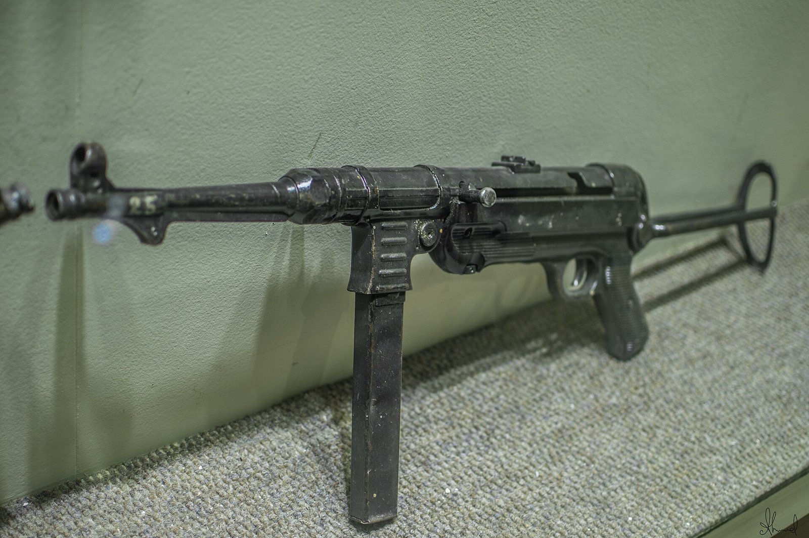
Phenolic resin is hard and brittle.4 Cracks in the grip frame — commonly at the stress points around the stock hinge and the grip’s junction with the receiver — are among the most frequent faults on surviving examples. Unlike a cracked wooden stock, a cracked phenolic moulding cannot be glued, sanded and refinished into an invisible repair, and original mouldings are consumable.
The folding stock hinge deserves separate attention for the same underlying reason: it is a stamped and hinged assembly carrying repeated loads, and a stock that will not lock firmly extended is both an accuracy problem and, as Volume 5 argued, the loss of the weapon’s single most distinctive virtue.
7.5 Inspecting a Collectible Example
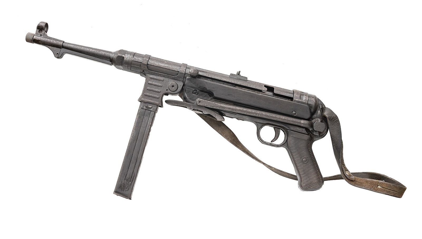
A checklist, in the order that resolves the most uncertainty first.
1. Establish what model it is. Volume 3’s identification discipline applies. A machined receiver with longitudinal flutes is an MP 38; a smooth rolled receiver is an MP 40; a smooth-sided magazine housing is suggestive of an MP 38 but is not conclusive, because the MP 40’s ribs are shallow and hide at the wrong angle. Check the receiver for flutes as the primary test. Remember also that the MP 38/40 designation is genuine and sits between the two.
2. Read the full receiver marking — code, year and serial. This is the MP 40-specific step and Volume 3 established why it is not optional: serial numbers repeat across makers and across years, so code + year + serial is the identifier and the serial alone is not.7 The codes are ayf for Erma, bnz for Steyr and fxo for Haenel — and, as Volumes 1 and 3 both record, that table rests on photographic and collector evidence rather than an authoritative published source, so a buyer relying on it should confirm it independently.
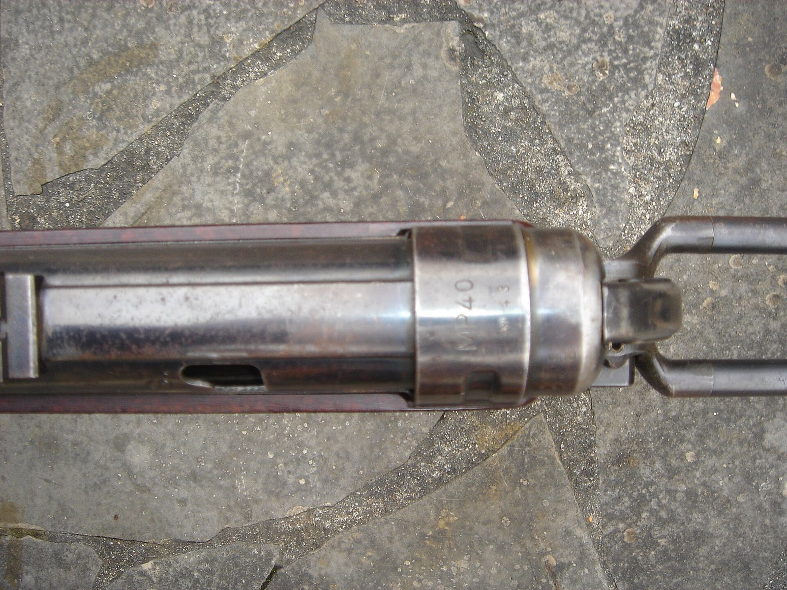
3. Check the paperwork against the metal. For a US transferable weapon this is the step with the largest downside if skipped; Volume 6 covers it.
4. Check for the safety retrofit. Look at the cocking-handle slot for the notch. Its absence tells two things at once: something about the weapon’s period and history, and something about how it must be handled (§ 7.1). The modification became standard from 1941 and older weapons were retrofitted, so an unretrofitted example is an early weapon that escaped the programme.2
5. Assess “matching numbers” sceptically. Parts were serialised to the weapon, but a claim of matching numbers on an MP 40 has to be read against the code and year as well as the digits, for the same reason as step 2. Two genuine wartime parts can carry the same number and belong to different guns.
6. Inspect the receiver for deformation, per § 7.4, in raking light.
7. Inspect the furniture for cracks, and note whether it appears original. Volume 3’s caution on terminology applies: the safe description is moulded phenolic resin, and whether a given set is true Bakelite or another phenolic formulation is not determinable by eye.
8. Test the magazine fit for play in the housing, per § 7.4.
9. Check the stock locks firmly both extended and folded.

7.6 The One Habit to Break

German soldiers “were trained to grasp either the handguard on the underside of the weapon or the magazine housing with the supporting hand to avoid feed malfunctions.”1
The magazine housing is not the magazine. The housing is the fixed sheet-metal shroud that is part of the weapon; the magazine is the removable box inside it. Gripping the housing is correct doctrine. Gripping the magazine tilts it in a well that does not hold it rigidly and takes the feed lips out of line.1
On a weapon whose magazine well was never a rigid fit when new, and which is now eighty years older, the margin for this error has not improved.
7.7 What Could Not Be Verified
- A field-strip or detailed-strip sequence. No original manual or citable takedown source was obtained; § 7.2 gives the constraints a correct procedure must satisfy instead of an invented one.
- Torque, clearance or headspace specifications, and any armourer’s gauge dimensions.
- Whether any particular furniture set is Bakelite specifically rather than another phenolic formulation.
- Original finish specifications, which this dive did not investigate.
7.8 Bibliography
Footnotes
-
“MP 40”, English Wikipedia, consulted 2026-09-17 — the cocking handle locking the bolt in either the cocked or uncocked position via two notches, the leather-harness field expedient on early MP 38s, the quoted passage that hand pressure on the magazine body could cause the magazine lips to move out of the line of feed “since the magazine well did not keep the magazine firmly locked”, and the quoted training instruction to grasp the handguard or the magazine housing with the supporting hand. ↩ ↩2 ↩3 ↩4 ↩5 ↩6 ↩7
-
“MP 40” and “MP 38”, German Wikipedia, consulted 2026-09-17 — the accidental-discharge hazard on the unmodified weapon, and the introduction of the locking device as standard equipment from 1941 with retrofitting of weapons already in service. ↩ ↩2
-
“MP 40”, English Wikipedia, consulted 2026-09-17 — the 9×19mm Parabellum chambering and 251 mm barrel. ↩
-
“Bakelite”, English Wikipedia, consulted 2026-09-17 — Bakelite as a thermosetting phenol formaldehyde resin, extremely hard and both infusible and insoluble, resistant to heat, scratches and solvents, and inflexible and brittle; and its distinction from later phenolic and urea resins. ↩ ↩2
-
“Sten”, English Wikipedia, consulted 2026-09-17 — the magazine’s double-column single-feed design, the 8-degree feed-lip angle requirement, and the malfunctions caused by deformed lips. ↩
-
Forgotten Weapons, “MP-40/I: The Dual-Magazine Experimental MP-40”, https://www.forgottenweapons.com/mp-40i-the-dual-magazine-experimental-mp-40/ — the creasing and other damage to the magazine well and ejection port areas caused by extra weight on the relatively thin receiver tube. ↩
-
Wikimedia Commons, File:Loghi MP40 (It).jpg by Lory Tek, CC BY-SA 4.0 — the schematic of MP 40 receiver markings demonstrating that the same serial number and suffix appears on weapons from the same maker in different years and from different makers in the same year. Discussed in full at Volume 3 § 3.7. ↩
Comments (0)