USB-C Power Delivery · Volume 5
Cables, Connectors and the GX Decision — Where PD Can Live in a Wired Gun
Three places to put the PD sink and what each does to D31, a USB-C receptacle in a printed shell, the cable classes and their limits, USB data and recoil power on one cable, and what PD adds to charging the wireless gun's pack
5.1 D31, and Why PD Does Not Reopen It Yet
Decision D31 (19 October 2026) put one GX aviation connector at the magazine base plate for everything: the USB pair, the 5 V and ground for the logic, and the 24 V rail, in one locking plug, with no barrel jack beside it. The brick’s 5.5 × 2.1 mm plug and the PC’s USB cable meet the gun’s cable at its far end. GX connectors are not for hot-plugging, so the plug is mated before the brick goes into the wall, and the pins are allocated so that a one-position slip cannot put the rail on a USB or logic pin (Power Supplies Vol 2, Reference Electronics Vol 8).
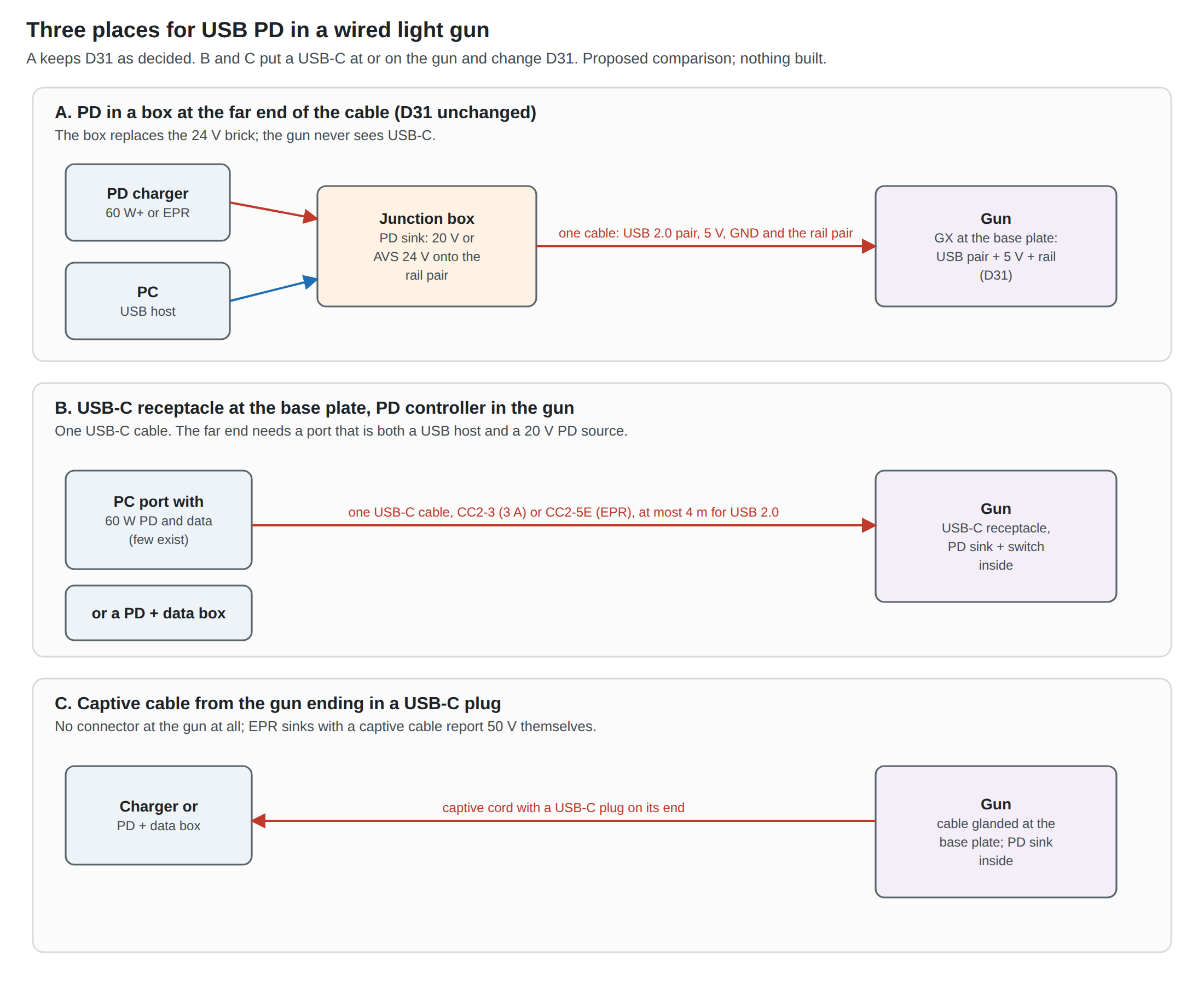
The question for this dive is whether USB-C PD can coexist with that. It can, in one arrangement without changing anything at the gun, and in two others that would change D31. The three are compared below.
5.2 Architecture A: the PD Sink in a Box at the Far End
The gun’s cable already ends somewhere: at the place where the brick’s barrel plug and the PC’s USB plug join it. Make that place a small box, and put the PD sink in the box.
- What goes in: a USB-C PD charger (60 W or more for 20 V; an EPR charger for AVS at 24 V), and the PC’s USB.
- What is in the box: a PD sink and its load switch (the SparkFun STUSB4500 board of Volume 4 for a first prototype; the STUSB4500 or AP33772S on a small board later); a soft-start switch; and the junction of the USB pair, 5 V and ground from the PC.
- What goes out: the existing gun cable, unchanged, with 20 V (or 24 V by AVS) on the rail pair instead of the brick’s 24 V.
Its advantages are all about what it does not change. The gun, its carrier board, its GX and its pin allocation are exactly as decided. The brick and the PD box are interchangeable at the box end, so the gun can be run from either and compared on the same coil. The reservoir and its soft start are already in the gun; the box only has to keep VBUS within the 100 µF rule on its own side. And the GX’s mating rule is easier to keep, because the PD box’s switch holds the rail off until a contract is reached: plug the GX, then the charger.
Its cost is the box, and the fact that the rail runs at 20 V rather than 24 V for a 20 V box, which is the coil question of Volume 2 rather than a connector question. This is the architecture this dive recommends for PD on the wired gun, as a second supply option beside the brick and not a replacement for it.
5.3 Architecture B: a USB-C Receptacle at the Base Plate
The alternative is the phone-like one: a USB-C receptacle in the gun, and the PD sink on the gun’s board. Reference Electronics Vol 8 already anticipates “USB-C where the cable leaves” for the Stage 2 custom board.
What changes. D31’s GX at the base plate becomes a USB-C receptacle; the carrier gains the PD front end of Volume 3, Section 3.5; and the cable becomes a standard USB-C cable. The rail pair, the separate 5 V and the pin-allocation argument disappear: VBUS carries the rail, and the logic takes its 5 V from the gun’s own regulator.
The receptacle in a printed shell. A Type-C receptacle is rated for 5 A,1 which covers the rail. What a printed MP7 base plate adds is mechanical. A plug is levered sideways in use far more than a GX plug, which locks; the receptacle must be held by its shell tabs through the board and by the plate around it, not by its solder joints. A mid-mount or through-hole-shell receptacle on a small daughterboard screwed to the plate, with the plate’s opening sized to the plug overmould so the plate takes the side load, is the usual answer. Volume 6 lists the parts to choose from at layout time; this dive does not pick one. Heat is not an issue at 3 A for a connector rated 5 A.
What it gives up. A USB-C plug does not lock. A trip over the cable unplugs the gun, which is safer for the gun and worse for the game. It is not hot-plug-proof in the way the design now assumes, though a correct PD sink (Volume 3) keeps the rail off until a contract and opens it on detach, so a USB-C gun is in fact more tolerant of hot-plugging than a GX one. And it needs a far end that can supply both USB data and 20 V on one cable (Section 5.5), which is the decisive problem.
5.4 Architecture C: a Captive Cable Ending in a USB-C Plug
The third option removes the connector at the gun entirely: the cable is glanded through the base plate, and its far end is a USB-C plug. For EPR this has a real advantage: the PD specification lets an EPR sink with a captive cable report the cable’s 50 V rating itself (“EPR Sinks with a captive cable Shall report 50V”),2 which is how the cheapest 28 V trigger boards work with an ordinary charger (WCH’s CH224 manual requires a Type-C plug for requests above 20 V or 60 W).3 It also costs nothing in the base plate except a strain relief.
It shares B’s far-end problem, and adds its own: the cable cannot be replaced without opening the gun, and the gun cannot use a longer or shorter one. For a printed first build (D35) that is easy to change later; for a kit (D11) it is a support question.
5.5 The One-Cable Problem: Who Is Both Host and 20 V Source?
Architectures B and C deliver USB data and recoil power on one USB-C cable. The far end of that cable must therefore be a port that is a USB host (for the RP2040’s HID data) and a PD source at 20 V or more (for the rail) at the same time.
Type-C allows it: a port’s power role (source or sink) and data role (host or device) are independent, and the default pairing, source with host, is exactly this one. The difficulty is that almost no PC port does it.
- Laptop USB-C ports source power at 5 V, usually 1.5 or 3 A. They are sinks at 20 V (that is how the laptop charges), not sources.
- Desktop front-panel ports on some current motherboards advertise more. ASUS’s ROG listings show several X870E and Z890 boards whose front-panel USB-C connector supports “Quick Charge 4+ up to 60W”, and others at “PD 3.0 up to 30W”; one user reports that the 60 W port needs an extra power connector on the board.4 Whether a 60 W port offers a 20 V, 3 A object, and on which boards, was not confirmed on any board’s own specification page for this dive.
- Hubs and docks generally pass PD power upstream to a laptop and give their downstream ports 5 V.
So a one-cable gun needs either one of the few motherboards with a high-power front port, or a PD-and-data box: something that takes the PC’s USB on one side and a charger or brick on the other, and presents a single USB-C port to the gun that is both host-side for data and a 20 V PD source. That box contains a PD source controller (the role of Infineon’s CCG3PA in Volume 3), and is a harder design than architecture A’s sink box. It is also exactly the box that architecture A makes unnecessary, by keeping the rail on its own conductors.
That is the core of the recommendation. Architecture A gets PD into the wired gun with a sink box and no change at the gun. B and C get a USB-C connector at the gun at the cost of a source box at the other end. For a wired gun B and C are only worth it when a single standard cable is itself the goal, as it might be for a kit (D11); that is a later decision.
5.6 Cables: Classes, Lengths and Drop
The Type-C specification defines the cable classes that matter here (Table 3-1, Release 2.5, March 2026):5
Table 1 — 5.6 Cables: Classes, Lengths and Drop
| Cable | USB data | Current | PD | Electronic marker | Practical length |
|---|---|---|---|---|---|
| CC2-3 | USB 2.0 | 3 A | SPR only | optional | ≤ 4 m |
| CC2-5E | USB 2.0 | 5 A | SPR and EPR | required | ≤ 4 m |
| CC3G1, CC3G2, CC4G3 | USB 3.2 / USB4 | 3 or 5 A | as above | required | 2 m, 1 m, 0.8 m |
Three consequences for a gun:
- A USB 2.0 cable is the right cable for a USB 1.1 HID gun: it has the longest allowed length (the living-room distance), it is the most flexible, and the 3 A version needs no marker. The SuperSpeed classes are shorter, stiffer and carry pairs the gun does not use.
- 3 A is enough for 20 V: one stage at 2.5 A plus logic stays under 3 A (Volume 2). A 5 A cable matters only for EPR, and for EPR the cable must be a marked 50 V, 5 A cable. The specification has deprecated the old 5 A SPR-only cables in favour of EPR ones, so any new 5 A cable should be EPR.5
- The drop is specified, not just measured. A compliant cable drops at most 500 mV on VBUS and 250 mV on ground at its rated current, contacts included.6 At the gun’s 2.5 A on a 3 A cable that is about 0.62 V; on a 5 A cable about 0.38 V.
For architecture A the cable to the gun is not a USB-C cable at all; it is the gun’s own multi-conductor lead to the GX, and its drop is the subject of Power Supplies Vol 2. The USB-C cable runs only from the charger to the box, and can be short.
5.7 USB Data and Recoil Current in One Jacket
Every one-cable design, including D31’s own cable, runs the coil’s pulse current beside the USB pair. Reference Electronics Vol 8 treats the EMI side (a twisted power pair and a shielded USB pair as the minimum), and Power Supplies Vol 5 owns ground shift and resets. PD adds one specific fact. In a USB-C cable the recoil current and the USB signal share one ground, and the specification allows that ground to drop 250 mV at the cable’s rated current. During a 2.5 A shot on a 3 A cable the gun’s ground can sit about 0.2 V above the host’s. USB full speed is a 3.3 V single-ended and differential bus with margin for that, and PD’s own BMC signalling is specified to tolerate it, but it is the same mechanism Power Supplies Vol 5 identifies behind “resets when it fires”. Architecture A avoids it by keeping the rail’s return on its own conductor from the box to the gun.
The data pair itself is untouched by PD. The sink controller is on CC; the RP2040 is on D+ and D−; the only rule is the one in Volume 1, that a sink chip with DP and DM pins must not be connected to the gun’s data pair.
5.8 PD and the Wireless Gun’s Pack
The LiPo Batteries dive has decided how the wireless gun’s 6S pack is charged for the first battery build: out of the gun, on a SkyRC B6neo balance charger fed from the same 24 V brick or from a PD charger (LB-5; LiPo Batteries Vol 5). That dive also sets out what an on-board PD charger would take (a PD sink and a BQ25756-class buck-boost charge controller) and why it was not chosen. Three PD facts complete that picture without repeating it.
- No SPR contract can charge a 6S pack directly. A full pack is 25.2 V; the highest SPR voltage is 20 V. An on-board charger is a buck-boost whichever contract it gets.
- 28 V fixed is barely above a full pack. At the bottom of its tolerance (26.6 V at the charger, 25.35 V at the sink) it leaves almost nothing for a buck converter’s dropout. EPR AVS is the better input for an on-board charger, for the same reason it is the better input for the rail: the charger can ask for exactly what it needs.
- The reference design exists. TI’s 240 W EPR battery-charger reference pairs the TPS26750 with the BQ25756 and, in TI’s words, needs “no external MCU or custom firmware”.7 If an on-board charger is ever revisited, that is its shape, and the TPS26750 in Volume 3 is the sink it uses.
5.9 Why This, and Why Not the Others
Table 2 — 5.9 Why This, and Why Not the Others
| Option | Verdict | Why | Why not |
|---|---|---|---|
| A: PD sink box at the far end, D31 unchanged | Proposed as the PD option for the wired gun | No change at the gun; brick and PD box interchangeable for comparison; rail and its return on their own conductors; sink box is simple (Volumes 3, 4) | A second box on the floor; the gun cable is still custom |
| B: USB-C receptacle at the base plate | Deferred to Stage 2 or a kit | One standard cable; PD sink makes it hot-plug tolerant | Changes D31; no lock; needs a host port that sources 20 V, or a PD source box; receptacle retention in a printed plate |
| C: captive cable with a USB-C plug | Deferred | No connector at the gun; EPR without an EPR cable | Changes D31; same far-end problem as B; cable not replaceable |
| USB 2.0 CC2-3 cable (for B or C) | Proposed if B or C is chosen | Longest (≤ 4 m), most flexible, enough for 20 V at 3 A | No EPR |
| CC2-5E EPR cable | Only for EPR | Required for 28 V or AVS above 20 V | Stiffer, marked, dearer; unnecessary at 20 V |
| On-board PD charging of the pack | Not chosen (LB-5 stands) | Single connector for charge and play | 6S needs a buck-boost from any contract; heat and charging inside PETG; see LiPo Batteries Vol 5 |
Sources
Footnotes
-
USB 3.0 Promoter Group, USB Type-C® Cable and Connector Specification, Release 2.5 (March 2026), §2.4: “The USB Type-C receptacle is specified for current capability of 5 A whereas standard USB Type-C cable assemblies are rated for 3 A.” https://www.usb.org/document-library/usb-type-cr-cable-and-connector-specification-release-24 (downloaded 2026-10-19). ↩
-
USB-IF, USB Power Delivery Specification r3.2 v1.2 (August 2026), cable VDO “Maximum VBUS Voltage” field. https://www.usb.org/document-library/usb-power-delivery (downloaded 2026-10-19). ↩
-
WCH, CH224 手册1, version 2.1, §5.3 (e-marker emulation). Copy: https://atta.szlcsc.com/upload/public/pdf/source/20250227/6D68A1393FFD6E9F0B2393231A5DDBA5.pdf (read 2026-10-19). ↩
-
ASUS ROG motherboard listings filtered by “Type-C Front Panel Connector”, e.g. https://rog.asus.com/motherboards-group/allmodels/?items=8543, and a pcgameshardware.de forum thread, “Suche PC-Gehäuse mit PD Power Delivery” (all via search results, 2026-10-19). Not confirmed on a single board’s specification page. ↩
-
Ibid., §3.1.2 and Table 3-1, USB Type-C Standard Cable Assemblies, with note 1 (5 A SPR cables deprecated). ↩ ↩2
-
Ibid., §4.4.1 IR Drop. ↩
-
A. McGaffin, Texas Instruments, SSZTD49A, October 2024, Table 2 and “Reference designs”, https://www.ti.com/lit/SSZTD49 (read 2026-10-19). ↩
Comments (0)