USB-C Power Delivery · Volume 3
Sink Controllers — Eight Chips Compared, and the Three Worth Designing In
CH224, IP2721, HUSB238A, STUSB4500, Infineon CYPD3177, TI TPS25751 and TPS26750, Diodes AP33772S: what each asks for, what it does when it cannot get it, whether it switches the rail, whether it touches the data pair, and why Infineon's CCG3PA is the wrong side of the cable
3.1 What the Gun Needs From a Sink Controller
Volumes 1 and 2 turn into seven requirements for the chip that negotiates the gun’s power:
- Request the right contract: 20 V fixed at 3 A for the ordinary-charger route, or EPR AVS at 24.0 V for the brick-equivalent route (Volume 2, Section 2.10).
- Refuse to power the rail on anything less, rather than settling for 15 V or 5 V (Volume 2, Section 2.9). A chip that signals the contract it got, in a form that can hold the load switch open, meets this; a chip that quietly takes the next voltage down does not, unless something else checks.
- Drive, or be paired with, a load switch that soft-starts the 1000 µF reservoir, opens on detach and hard reset, and blocks the coast energy from flowing back onto VBUS (Volume 1, Section 1.7).
- Leave D+ and D− alone. The data pair belongs to the RP2040 (Volume 1, Section 1.2).
- Survive the voltages: at least the 24 V the specification asks every sink to tolerate, and the 28 V class with margin if EPR is used.
- Keep the contract alive without the firmware’s help where possible: EPR keep-alives every 250 to 500 ms, PPS re-requests every 10 s.
- Be buildable and buyable: a package the lab can reflow, an English data sheet good enough to design from, and a seller who has it. D11 (kits may be sold) makes the last point binding, as it did for the camera (D18).
3.2 The Candidates
WCH CH224 family. The parts on most cheap “decoy” boards. WCH’s own manual (version 2.1, Chinese) splits them in two: the CH224K, CH224D and CH221K are PD 3.0 parts “up to 100 W”, configured by one resistor or three logic levels; the CH224Q and CH224A support “PD3.2 EPR 140 W”, PPS, AVS and I2C.1 On the new parts, one resistor on CFG1 selects 9, 12, 15, 20 or 28 V (6.8, 24, 56, 120 or 210 kΩ); the I2C registers request 5 to 28 V, PPS or AVS, report the present object’s current in 50 mA units, and expose the whole capability list. Absolute maximum on VBUS, CC and the supply is 32 V on the Q/A, with a supply over-voltage reset at 32 to 34 V. Three cautions. Neither CH224 switches the rail; the open-drain PG pin says the contract is good and the board must do the switching. DP and DM are fast-charge pins, used for BC1.2 and QC. And the same pins mean different voltages on different variants: CFG1/2/3 = 0/1/0 requests 20 V on a CH224K and 28 V on a CH224A, which WCH acknowledges (“the resistor values or I/O-level voltages are not exactly the same”). The CH224K’s English data sheet has been withdrawn, according to the German microcontroller.net parts page. On 19 October 2026 LCSC’s CH224K listing (C970725) showed “Not available now”, and no LCSC listing was found for the CH224Q or CH224A.
Injoinic IP2721. A 2017 PD 2.0/3.0 sink in TSSOP-16. One pin, SEL, chooses the maximum request: high for 20 V, floating for 15 V, ground for 5 V. It drives an external N-MOSFET from its VBUSG pin with a 3.5 to 4.5 ms soft start, works from 3 to 25 V, and tolerates 30 V on VIN and CC. It has no D+ or D− pins.2 A builder of a TS100 iron supply found that SEL tied straight to the supply negotiated 5 V and needed a 100 kΩ resistor to negotiate 20 V.3 LCSC (C603176) showed it out of stock on 19 October 2026 at a reference $0.76 each, $0.49 at 100. DigiKey does not stock it.
Hynetek HUSB238A. The EPR successor to the HUSB238 on Adafruit’s breakout (Volume 4). In GPIO mode, two resistors set up to 28 V and 3.25 A; in I2C mode it reaches EPR fixed objects, EPR AVS and SPR PPS. It has an integrated driver for an external VBUS switch (open-drain GATE), over- and under-voltage and thermal protection, e-marker emulation on SOP′, and legacy BC1.2, Apple divider and QC detection on D+ and D−. VBUS operates to 29.4 V, absolute maximum 33 V, so despite the “48 V/5 A” on its front page it is a 28 V part in practice. QFN 3 × 3 mm.4
ST STUSB4500. The best-documented standalone sink. Three sink objects in non-volatile memory (5 V fixed, then two programmable from 5 to 20 V in 50 mV steps, 0.5 to 5 A); PD 2.0 certified and “interoperable with USB PD rev 3.0”; VBUS pins rated 28 V; CC protected to 22 V; integrated gate drivers for P-MOSFET power switches; QFN-24 4 × 4 mm or a 25-ball WLCSP. No PPS, no EPR, no D+ or D− pins.5 It is on SparkFun’s PD board (Volume 4), which makes it the easiest to try.
Infineon CYPD3177 (EZ-PD BCR). A pre-programmed “barrel connector replacement” sink: 5, 9, 12, 15 or 20 V up to 5 A, set by resistors, no firmware; 3.0 to 24.5 V operation, 30 V tolerant, with an LDO, a VBUS gate driver and a discharge FET on chip (from Infineon’s summaries; the data sheet itself was not retrieved). Its two outputs are what the gun needs: Infineon staff, quoting the data sheet, say “VBUS_FET_EN is enabled when the EZ-PD BCR device successfully negotiates a power contract within the requested range, while SAFE_PWR_EN is enabled when the EZ-PD BCR device fails to negotiate for higher power and defaults to 5V.”6 QFN-24 4 × 4 mm. LCSC (C5904158, CYPD3177-24LQXQT) showed 3 in stock at $1.50 each, $0.94 at 100, on 19 October 2026.
TI TPS25750 and TPS25751. Full PD controllers “optimized for power applications”, configured with TI’s web tool. The TPS25750 is marked “NOT RECOMMENDED FOR NEW DESIGNS” on TI’s product page (read 19 October 2026). Its active successor, the TPS25751 (PD 3.1 certified, SPR), has in its D variant an integrated 20 V, 5 A, 16 mΩ bidirectional load switch with “reverse current protection, undervoltage protection, overvoltage protection, and slew rate control”, liquid detection on the connector, PPS, and I2C control of TI battery chargers.7 Its configuration loads at boot from an external I2C EEPROM (at least 32 KB on the TPS25750; the TPS25751 sheet should be checked) or from a host. It is the one chip that does requirements 2, 3 and 5 for 20 V on its own silicon.
TI TPS26750. The EPR member: certified PD 3.1, EPR source and sink at 28, 36 and 48 V with AVS, PPS, liquid detection; the high-voltage path through external MOSFETs; configuration from an EEPROM of at least 36 KB or a host; QFN-32 4 × 4 mm. TI pairs it with the BQ25756 buck-boost charger in a 240 W reference design.89 It is a battery-system part and more than the gun needs, except as the controller for an on-board LiPo charger (Volume 5).
Diodes AP33772S. An “I2C USB PD3.1 EPR sink controller”: EPR AVS up to 28 V, SPR PPS up to 21 V, PD 3.1 certified (TID 10062), VCC 3 to 31 V, CC short protection to 34 V, OVP with hard reset and auto-restart, UVP, OCP and OTP with latch-off, NTC derating, moisture detection, and a PWR_EN driver for an output N-MOSFET, in a 4 × 4 mm QFN-24. It “is targeted for … devices with an embedded host MCU”: the host writes the profile over I2C and “delegates PD negotiation tasks to the AP33772S”.10 It has DP and DN pins for legacy Type-A charger support.
Infineon CCG3PA, named in this dive’s brief, is not a sink controller. Its data sheet describes it as a single-chip USB-C PD controller for “power adapters, mobile chargers, power banks and car chargers”, with feedback circuitry to regulate VBUS on the secondary side of a power supply.11 It is what sits inside a charger. It belongs in the gun only if the gun is to supply USB-C power, which no design here does.
3.3 The Comparison Table
Table 1 — 3.3 The Comparison Table
| Chip | PD | Highest request | PPS / AVS / EPR | Set by | Switches the rail | On a mismatch | Uses D+/D− | VBUS rating | Price and stock (19 Oct 2026) |
|---|---|---|---|---|---|---|---|---|---|
| CH224K | 3.0 | 20 V | no | resistor or 3 pins | no (PG flag) | not documented | yes (BC1.2, QC) | 13.5 V on the VBUS sense pin, through a resistor | LCSC: not available |
| CH224Q / A | 3.2 | 28 V | yes / yes / yes | resistor, pins or I2C | no (PG flag) | not documented | yes | 32 V abs. max | no listing found |
| IP2721 | 2.0/3.0 | 20 V | no | 3-level SEL pin | N-FET driver | takes a lower voltage (“maximum” request) | no | 25 V operating, 30 V abs. max | LCSC $0.76, out of stock |
| HUSB238A | 3.1 | 28 V | I2C / yes / yes | 2 resistors or I2C | N-FET driver (GATE) | next lower object | yes | 29.4 V operating, 33 V abs. max | not read |
| STUSB4500 | 2.0 cert., 3.0 interop. | 20 V | no | NVM over I2C | P-FET drivers | 5 V; switch can be held off below the configured objects | no | 28 V | not read |
| CYPD3177 | not read | 20 V | no | resistors | P-FET driver | 5 V, on a separate output | not documented | 24.5 V operating, 30 V tolerant | LCSC $1.50, 3 in stock |
| TPS25751D | 3.1 cert. | 20 V | PPS / no / no | EEPROM or host | integrated 20 V 5 A switch with RCP, OVP, slew control | configurable | not checked | 28 V abs. max on PPHV | not shown without login |
| TPS26750 | 3.1 cert. | 48 V | yes / yes / yes | EEPROM or host | external FETs | configurable | not checked | external path | not shown |
| AP33772S | 3.1 cert. | 28 V | PPS / AVS / EPR | I2C host only | N-FET driver with OVP/UVP/OCP | host decides | DP/DN (legacy) | 31 V abs. max on VOUT | not read |
“Not read” means the price was not taken from a seller’s page during this research; price at order time.
3.4 Fallback: the Behaviour That Decides Safety
Requirement 2 is where the chips differ most, and where their data sheets have to be read word for word.
- STUSB4500: a match needs the voltage to be equal, “V(SNK_PDOi) = V(SRC_PDOj)”, highest-priority object first; with no match “the USB PD negotiation ends with an explicit USB PD contract at 5 V”. A non-volatile bit, POWER_ONLY_ABOVE_5V, then keeps the VBUS_EN_SNK switch output off unless a PDO2 or PDO3 contract was reached.5 Configure both PDO2 and PDO3 as 20 V and set that bit, and the rail is connected on a 20 V contract and on nothing else. That is exactly requirement 2, in hardware, with no firmware.
- CYPD3177: the same idea with two pins: VBUS_FET_EN for “a power contract within the requested range”, SAFE_PWR_EN for the 5 V fallback.6 Leave SAFE_PWR_EN unconnected and the rail sees nothing but the requested range.
- HUSB238A: takes the highest object at or below its target, so 20 V requested from a 45 W charger yields 15 V, and its GATE output closes the switch on it.4 Usable only with a check after it: in I2C mode the host reads the contract; in GPIO mode the rail needs its own under-voltage lockout.
- IP2721: SEL sets a maximum; the behaviour on a lower charger is a lower contract, with the switch closed.
- CH224: the manual does not say. PG means “power good” for whatever was obtained.
- AP33772S, TPS25751, TPS26750: whatever the configuration or host says, which is the point of them.
A light gun on a lower contract does not fail loudly. Its kick arrives late or not at all, and on a hard reset its rail drops through every intermediate voltage. For the two chips that take whatever they can get, the design must add an under-voltage lockout on the rail switch, set above the worst case the design accepts. The LiPo Batteries dive’s choice of an LM5060 rail switch, with its adjustable under-voltage lockout, soft start and over-voltage cut, is one way (LiPo Batteries Vol 4). One caution if that part is shared between a battery and a PD input: its lockout is set at about 19.5 V falling for the 6S pack, and a 20 V PD contract can legally be as low as 19.0 V at the charger and 17.75 V at the sink. A PD-fed rail needs its own threshold, about 17 V.
3.5 The Power Path Behind the Chip
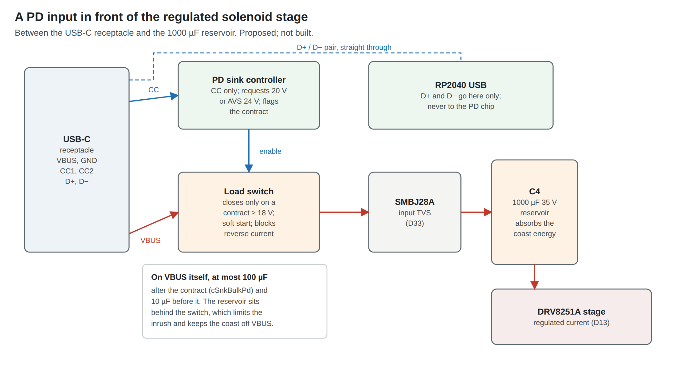
Whichever chip negotiates, the same five things sit between the receptacle and the stage:
- On VBUS, before the switch: the receptacle, a local ceramic of a few microfarads, and nothing that takes the total over 10 µF (cSnkBulk) before the contract or 100 µF (cSnkBulkPd) after it.
- The load switch. It opens with no contract, on detach and on hard reset, so the reservoir is “removed” as the specification requires. It soft-starts the reservoir: a 1000 µF capacitor at 1 V/ms draws 1 A and is full at 20 V in 20 ms. And it blocks reverse current, so that the coast energy of every shot stays on the gun’s side. Back-to-back MOSFETs (common source) give both directions of blocking; the TPS25751D does it on chip.
- The input TVS of D33, the SMBJ28A, on the rail side of the switch, where the rail actually lives.
- The reservoir, C4 on the Reference Electronics carrier, 1000 µF at 35 V, unchanged.
- The stage. Its 2 V/µs limit on supply slew (Reference Electronics Vol 5) is met by the soft start.
On the gun’s logic side nothing changes: in the wired design the RP2040 is powered from the PC’s 5 V on its own conductors, so a PD hard reset costs a second of recoil and nothing else.
3.6 The Picks
For a 20 V input, where it lives outside the gun (the cable-end box of Volume 5’s architecture A): ST STUSB4500. It meets requirement 2 in hardware with no firmware (two 20 V objects and POWER_ONLY_ABOVE_5V), drives P-FET switches directly, rates its VBUS pins at 28 V, never touches the data pair, has an English data sheet with every register described, and is on a ready-made SparkFun board for the bench. Its limits are SPR-only and PD 2.0 certification, neither of which matters for a fixed 20 V contract.
For a 20 V input inside the gun (Volume 5’s architecture B or C, a later custom board): TI TPS25751D. The integrated 20 V, 5 A switch with reverse-current protection, over- and under-voltage protection and slew control is requirement 3 on one die, which is the part of the front end most likely to be got wrong discretely. The cost is a configuration image, in an EEPROM or loaded by the Pico at boot, which is a job for the Our Firmware fork or a one-time EEPROM programming step.
For EPR AVS at 24 V: Diodes AP33772S. It is the only EPR sink in the survey with a full English data sheet, USB-IF certification, its own protected N-FET switch output, and AVS from 15 to 28 V. It needs an I2C host. On the gun that host is the Pico, on the shared I2C1 bus that already carries the IMU (D36) and the OLED (D37); the firmware writes the requested voltage, waits for the interrupt and reads the status. In the cable-end box the host can be a small microcontroller of its own. The HUSB238A is the alternative if the AP33772S cannot be bought: it can request EPR AVS too, in I2C mode, and costs a board less in area, at the price of the “next lower object” fallback and D+/D− pins that must be left open.
None of the three is bought yet, and none of their prices was read from a seller’s page during this research.
3.7 Why This, and Why Not the Others
Table 2 — 3.7 Why This, and Why Not the Others
| Candidate | Verdict | Why | Why not |
|---|---|---|---|
| STUSB4500 | Proposed: 20 V box and bench | Exact-match request; rail switched only on the configured objects; P-FET drivers; 28 V VBUS; no D+/D−; SparkFun board | No PPS, no EPR; PD 2.0 certified |
| TPS25751D | Proposed: 20 V inside the gun, Stage 2 | Integrated 20 V 5 A switch with reverse-current protection, OVP, UVP, slew control; certified PD 3.1 | Needs an EEPROM or host configuration; SPR only |
| AP33772S | Proposed: EPR AVS 24 V | AVS 15–28 V, certified, protected N-FET driver, English data sheet | Needs an I2C host and firmware; DP/DN pins to leave open |
| HUSB238A | Alternative to the AP33772S | EPR AVS in I2C mode; GATE driver; small | Falls back to the next lower object; uses D+/D− for legacy protocols; data sheet only via distributor copies |
| CYPD3177 | Alternative to the STUSB4500 | Separate outputs for “in range” and “fell back to 5 V”; no firmware; on LCSC | 20 V maximum; its data sheet not read for this dive; 3 in stock at LCSC |
| CH224Q / CH224A | Not chosen | Cheap; 28 V, AVS and PPS over I2C | No rail switch; DP/DM on the data lines; Chinese-only manual; pin meanings differ between variants; no stock found |
| CH224K | Rejected | — | Superseded and unavailable; English data sheet withdrawn; fallback behaviour undocumented |
| IP2721 | Rejected | Simple; N-FET driver | Takes a lower contract; out of stock; not at DigiKey |
| TPS25750 | Rejected | — | “Not recommended for new designs”; the TPS25751 replaces it |
| TPS26750 | Not for the rail | EPR to 48 V, AVS, PPS | Overkill for a 24 V sink; external FETs and a 36 KB configuration; right for an on-board battery charger |
| CCG3PA | Wrong role | — | A source controller for chargers, not a sink |
Sources
Footnotes
-
WCH, CH224 手册1 (CH224 manual 1), version 2.1. Copy: https://atta.szlcsc.com/upload/public/pdf/source/20250227/6D68A1393FFD6E9F0B2393231A5DDBA5.pdf (read 2026-10-19): §1 overview, §2 features, Table 3-1 packages, Tables 5-1 and 5-2 (CH224Q/A configuration), §5.2.3 registers 0x09, 0x0A, 0x50–0x53, 0x60–0x8F, §6.2 (CH224K I/O table), §7.1 and §7.3 (differences between CH224A and CH224K), §8.1 absolute maximum ratings, §8.2.1 electrical parameters. CH224K datasheet withdrawal: microcontroller.net parts page “CH224K”, https://www.mikrocontroller.net/part/CH224K (search result, 2026-10-19). LCSC C970725, https://www.lcsc.com/product-detail/C970725.html (read 2026-10-19). ↩
-
Injoinic, IP2721 TYPEC/PD2.0/PD3.0 Physical Layer IC for USB TYPEC input Interfaces, V1.02. Copy: https://atta.szlcsc.com/upload/public/pdf/source/20200610/C603176_729C2C55A9E6451BDA9FCB913350E23E.pdf (read 2026-10-19). LCSC C603176, https://lcsc.com/product-detail/USB-PD_INJOINIC-IP2721_C603176.html (read 2026-10-19). DigiKey forum, “Alternative for IP2721 from Injoinic Technology”, https://forum.digikey.com/t/alternative-for-ip2721-from-injoinic-technology/30118 (search result, 2026-10-19). ↩
-
Hackaday.io project 172187, “An Open Source external module for powering a stock TS100 Soldering Iron using USB C Power Delivery”, log https://hackaday.io/project/172187/log/179029 (search result, 2026-10-19). ↩
-
Hynetek, HUSB238A USB PD EPR Sink Controller, Rev. 1.1. Copy: https://atta.szlcsc.com/upload/public/pdf/source/20250807/BD7DDAA8DFA1B07F0B3606C6A260D6C7.pdf (read 2026-10-19): features; recommended operating conditions; absolute maximum ratings; Tables 8 and 9; “RDO in GPIO Mode”; ordering guide. ↩ ↩2
-
STMicroelectronics, STUSB4500 Standalone USB PD sink controller with short-to-VBUS protections, DS12499 Rev 8, November 2022, https://www.st.com/resource/en/datasheet/stusb4500.pdf (downloaded 2026-10-19): features; §2.2.8 POWER_OK pins; VBUS_EN_SNK and POWER_ONLY_ABOVE_5V; §3.3.1–3.3.2 sink PDOs and decision algorithm. ↩ ↩2
-
Infineon, CYPD3177-24LQXQ product listing, https://www.infineon.com/cms/en/product/universal-serial-bus/usb-c-charging-port-controllers/ez-pd-barrel-connector-replacement-bcr/cypd3177-24lqxq/ (summary via search, 2026-10-19); Infineon Developer Community, “Signaling out of CYPD3177 FET_EN”, https://community.infineon.com/t5/USB-EZ-PD-Type-C/Signaling-out-of-CYPD3177-FET-EN/td-p/443209 (search result, 2026-10-19); LCSC C5904158, https://lcsc.com/product-detail/C5904158.html (read 2026-10-19). ↩ ↩2
-
Texas Instruments, TPS25751 USB Type-C® and USB PD Controller with Integrated Power Switches Optimized for Power Applications, SLVSH93A, October 2023, revised March 2024, https://www.ti.com/lit/ds/symlink/tps25751.pdf (downloaded 2026-10-19); product status from https://www.ti.com/product/TPS25751 and https://www.ti.com/product/TPS25750 (read 2026-10-19); TPS25750 data sheet SLVSFR7A, https://www.ti.com/lit/ds/symlink/tps25750.pdf (EEPROM at 0x50, at least 32 KB). ↩
-
Texas Instruments, TPS26750 USB Type-C® and USB PD Controller With Integrated Power Switches Optimized for Power Applications, SLVSH67, September 2024, https://www.ti.com/lit/ds/symlink/tps26750.pdf (downloaded 2026-10-19). ↩
-
A. McGaffin, Texas Instruments, technical article SSZTD49A, October 2024, Table 2, https://www.ti.com/lit/SSZTD49 (read 2026-10-19). ↩
-
Diodes Incorporated, AP33772S I2C USB PD3.1 EPR Sink Controller, DS46176 Rev. 10-2, August 2026, https://www.diodes.com/assets/Datasheets/AP33772S.pdf (downloaded 2026-10-19). ↩
-
Infineon, EZ-PD™ CCG3PA USB Type-C Port Controller data sheet, document 002-16951, https://www.infineon.com/assets/row/public/documents/24/49/infineon-ez-pdtm-ccg3pa-datasheet-usb-type-c-port-controller-datasheet-en.pdf, and the CCG3PA product page (both via search, 2026-10-19). ↩
Comments (0)