USB-C Power Delivery · Volume 4
Trigger Boards and Decoys — Ready-Made PD Sinks for the Bench and the Cable Box
Adafruit's HUSB238 breakout, SparkFun's STUSB4500 board and the two-dollar 28 V decoys: what each really does on a charger that cannot give what it asks, the five checks before trusting one, and where a trigger board belongs in this project and where it does not
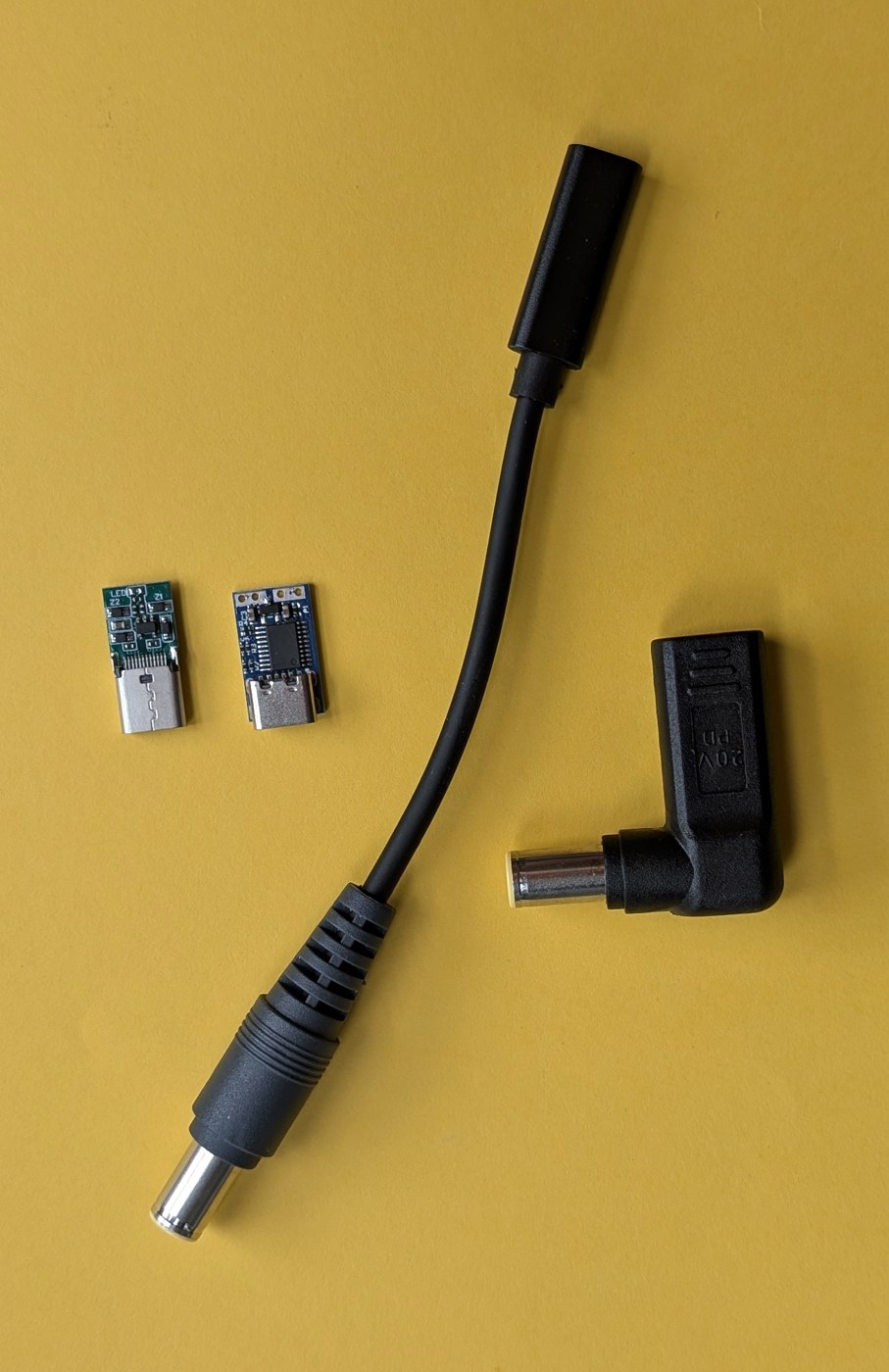
4.1 What a Trigger Board Is
A trigger board, sold as a “decoy”, “dummy” or “PD emulator”, is the smallest possible PD sink: a USB-C receptacle or plug, one of the chips of Volume 3, a few resistors that choose the request, and two output terminals. Plugged into a charger it sends a Request, receives PS_RDY, and leaves 9, 12, 15, 20 or 28 V on its terminals. The name “decoy” is apt: to the charger it looks like a laptop asking for power.
They are useful, cheap and widely misused. The misuse is always the same: the board is treated as a power supply of the voltage printed on its jumper, when it is really a negotiator that gets whatever the charger and its own fallback rule allow (Volume 3, Section 3.4). This volume describes the three kinds worth knowing and the checks that make one safe to put in front of a recoil stage.
4.2 Adafruit 5807: HUSB238, Jumpers or I2C
Adafruit’s “USB Type C Power Delivery Dummy Breakout - I2C or Fixed” (product 5807) carries Hynetek’s HUSB238, the SPR predecessor of the HUSB238A in Volume 3. It was $5.95 on Adafruit’s page on 19 October 2026 ($5.36 for 10 to 99, $4.76 for 100 or more).1
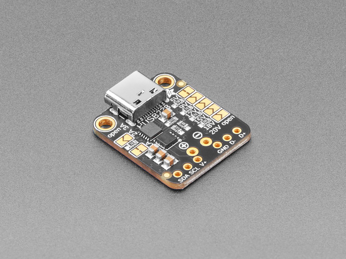
What Adafruit’s page says it does:
- out of the box it gives 5 V at 1 A, “since USB C provides 5V first”;
- cutting the 5 V jumper and closing one of the others selects 9, 12, 15, 18 or 20 V; other jumpers select 2 to 3 A, which Adafruit describes as less essential;
- or, over I2C with Adafruit’s Arduino library, a host can read the charger’s capabilities and choose one, with the jumper setting applying at power-up until the first I2C command; the board has no regulator and no I2C pull-ups, so the host provides both;
- up to “20V at 5A”, 100 W, with a suitable charger and cable.
Three things to know before using it with the gun’s rail. The 18 V jumper is not a PD voltage. No charger offers an 18 V fixed object, so what the chip requests with it set is decided by its fallback rule; the HUSB238A takes the highest object at or below its target, which here would be 15 V. Leave that jumper alone. D+ and D− are on pads, because the HUSB238 family detects legacy fast-charge protocols on them; on the bench nothing is connected there, and that is how it should stay. Its output is not switched off by default between plug-in and negotiation: the page’s own description is that it gives 5 V first. A recoil stage behind it sees 5 V, then the negotiated voltage.
Its I2C mode is its real value here. With a Pico as host on the bench, the board becomes a capability reader: plug in each charger in the house, print what it offers, request each object in turn, and log what arrives. That is test T1 of Volume 6, done for six dollars.
4.3 SparkFun DEV-15801: STUSB4500 on Qwiic
SparkFun’s “Power Delivery Board - USB-C (Qwiic)”, DEV-15801, carries ST’s STUSB4500, the chip proposed in Volume 3 for a 20 V cable-end box. It was $31.92 on SparkFun’s page on 19 October 2026, in stock ($30.32 for 10, $28.73 for 25, $27.13 for 100), described as 5 to 20 V, up to 5 A and 100 W, with three power profiles stored in non-volatile memory and set over I2C through its Qwiic connector or plated holes.2
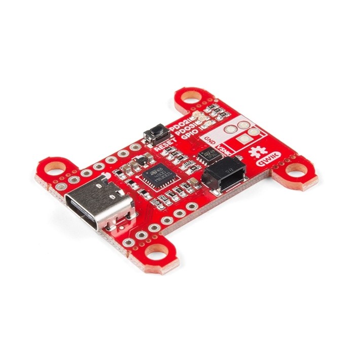
It costs five times the Adafruit board, and it is the one to buy for this project, because the STUSB4500’s fallback is the one the gun needs (Volume 3, Section 3.4). Program it once over Qwiic:
- PDO3 = 20 V, 3 A; PDO2 = 20 V, 3 A (so the only acceptable match is 20 V);
- POWER_ONLY_ABOVE_5V = 1 (so the board’s output switch closes only on a PDO2 or PDO3 contract);
- then disconnect the I2C host; the settings stay in the chip’s memory.
On a 60 W charger its output is then 20 V. On a 45 W charger it is nothing at all, rather than 15 V, and on a hard reset it is nothing until the next 20 V contract. That is requirement 2 of Volume 3, out of the box.
Two limits: the board is SPR only (no PPS, no AVS, no EPR), and the switched output has whatever capacitance SparkFun fitted, which should be read from its schematic before a 1000 µF reservoir is hung on it through a soft-start switch (Section 4.5).
4.4 The Two-Dollar Decoys, 20 V and 28 V
Below the maker boards is a market of anonymous modules sold on marketplaces. Two kinds matter here.
20 V modules, mostly built on the IP2721 or the CH224K (the photograph in Section 4.1 shows an IP2721 one). They cost a dollar or two. Their behaviour on a lower charger is the chip’s: the IP2721’s SEL sets a maximum, and the CH224K’s is undocumented. Gough’s Tech Zone, reviewing one CH224K board, found it “simply wouldn’t work properly with USB-C PD but managed to work on legacy fast-charging protocols”, which on a gun means it would talk to the charger on the data lines.3
28 V “PD 3.1 140 W” modules. In October 2026 these were listed at about €1.99 shipped from China (one eBay listing did not ship to the US) and as a four-pack for $56.99 on Newegg. The Newegg listing’s own text is the best summary of their limits: to get 28 V “the 140W supply must be connected to only one cable with an E-mark”, and “if the power supply does not support the requested voltage, it will be provided the next lowest voltage”.4 The listings do not name the chip; the CH224Q/A and HUSB238A are the 28 V candidates, and both fall back downward in the absence of a host.
For this project’s rail, a 28 V decoy is the wrong board twice over: 28 V fixed is the contract Volume 2 rejects (it sits on the clamp), and the fallback is the behaviour Volume 3 rejects. A 20 V marketplace decoy can serve on the bench as a cheap 20 V source after the checks below, never as the input to a gun that leaves the bench.
4.5 Five Checks Before Trusting Any Trigger Board
Each takes minutes on the ADP3450 and a bench load, and each has caught real boards out (Section 4.4).
- What does it give on a charger without the requested voltage? Plug it into a 30 W or 45 W charger (no 20 V object) and measure. The answer must be “nothing”, or the design must add an under-voltage lockout after it.
- Is the output live before negotiation? Capture the output on a ×10 probe from the moment of plug-in. If 5 V appears first, as on the Adafruit board, the recoil stage must be disabled until the rail is above 18 V.
- What is on D+ and D−? Look at the board. If the chip’s DP/DM pins are connected to the receptacle, the board must never share a cable with the gun’s USB data.
- What capacitance is on its output, and does it soft-start? Measure the inrush into the intended load. A trigger board’s own output capacitor is on VBUS for PD purposes; adding the gun’s 1000 µF directly behind it breaks the 100 µF cSnkBulkPd limit (Volume 1, Section 1.7) and draws tens of amps from the charger at the moment the contract completes.
- What does it do on a hard reset? Pull and reinsert the charger end mid-capture, then force a reset (a PD analyser can send one; Volume 6). Watch the output go to 0 and come back, and what voltage it comes back at.
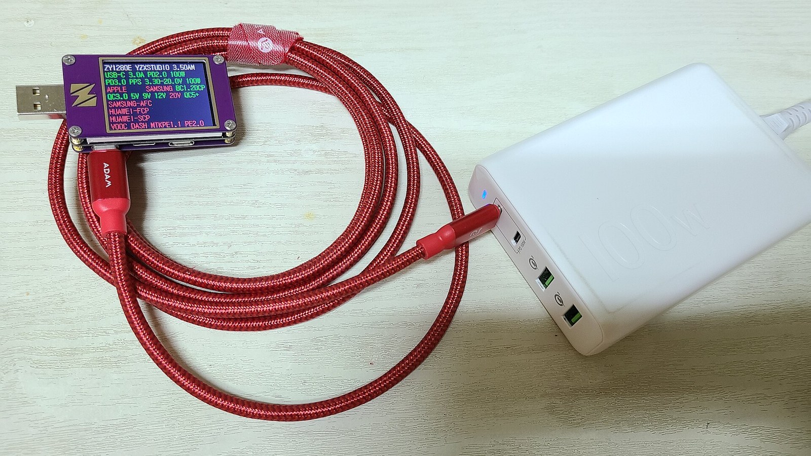
A USB power meter with a PD readout makes checks 1 and 5 quicker. Many hobby meters list the protocols and objects a charger offers on their screen.
4.6 Where a Trigger Board Belongs in This Project
On the bench, now. The Solenoid Recoil bench (D15) sweeps the coil from 12 to 28 V on programmable supplies. A SparkFun board set for 20 V, on the household’s laptop chargers, adds the one condition a programmable supply cannot reproduce: a real charger’s response to a 2.5 A step, its tolerance, and its behaviour on a reset. Volume 6 sets out the tests.
In a cable-end box, as the first PD prototype. Volume 5’s architecture A puts the PD sink at the far end of the gun’s cable, where the 24 V brick would otherwise plug in, and leaves the gun and its GX connector (D31) exactly as decided. A SparkFun board, a back-to-back MOSFET switch with a soft start, and the brick’s own 5.5 × 2.1 mm plug in a small printed enclosure is that box. The gun cannot tell it from the brick, except that its rail is 20 V instead of 24.
Not inside the gun. A trigger board in the gun means a USB-C receptacle at the base plate, which is a change to D31, and a board whose output switching, capacitance and data-pin wiring were designed for someone else’s product. When PD moves into the gun it does so on the custom board (Volume 3’s TPS25751D or AP33772S), designed to Volume 3, Section 3.5.
4.7 Why This, and Why Not the Others
Table 1 — 4.7 Why This, and Why Not the Others
| Board | Verdict | Why | Why not |
|---|---|---|---|
| SparkFun DEV-15801 (STUSB4500), $31.92 | Proposed: bench and cable-box prototype | Output switched only on the configured 20 V contract; no D+/D− on the chip; NVM keeps the settings | SPR only; five times the price of the Adafruit board |
| Adafruit 5807 (HUSB238), $5.95 | Proposed as a capability reader on the bench | I2C reads every object a charger offers; cheap; Arduino library | 5 V first; falls back to lower voltages; 18 V jumper is not a PD voltage |
| 20 V marketplace decoys (IP2721, CH224K) | Bench only, after the five checks | A dollar or two | Fallback undocumented or downward; at least one CH224K board talks on D+/D−; no seller documentation |
| 28 V marketplace decoys | Rejected | — | 28 V is rejected on the D14 rail (Volume 2); fall back to the next lower voltage; chip unknown |
| Any trigger board inside the gun | Rejected | — | Changes D31; output, capacitance and data pins designed for another product |
Sources
Footnotes
-
Adafruit, “Adafruit USB Type C Power Delivery Dummy Breakout - I2C or Fixed”, product 5807, https://www.adafruit.com/product/5807 (read 2026-10-19). Photo: https://cdn-shop.adafruit.com/1200x900/5807-00.jpg. ↩
-
SparkFun Electronics, “SparkFun Power Delivery Board - USB-C (Qwiic)”, DEV-15801, https://www.sparkfun.com/products/15801 (read 2026-10-19). ↩
-
Gough’s Tech Zone, review of a CH224K-based PD trigger board (search-result excerpt, 2026-10-19); the full review was not read. ↩
-
eBay listing 166831219333, “140W USB-C Fast Charge Trigger Board Module PD/QC Decoy Board PD3.1 28V/36V/48V” (ebay.de), and a Newegg four-pack listing, both seen as search results on 2026-10-19; prices and quoted text from the search excerpts, not from a full page read. ↩

Comments (0)