USB-C Power Delivery · Volume 2
Can a PD Charger Replace the 24 V Brick? — 20 V, PPS, 28 V and AVS Against the Rail Window
The forcing ratio each contract gives a regulated coil, why a shot fits under a 3 A contract, why 20 V plus a boost is worse than it looks, why 28 V sits on the clamp, which chargers actually offer 28 V, and the contract that matches the brick
2.1 The Question, and What Regulation Changes
Power Supplies Vol 2 deferred one row of its supply table to this dive: “A USB PD charger — 20 V at up to 3 A fits the window; it needs a PD sink in the gun.” This volume answers it.
The answer depends on a decision made before PD came up. Under regulated current (D13), the DRV8251A stage sets the coil current, and with it the ampere-turns and the kick. The supply voltage stops setting the kick and becomes the headroom: how fast the current reaches its set point, and whether it can reach it at all with a hot coil. Solenoid Recoil Vol 8 measures that headroom as the forcing ratio, k = V_supply / (I_target · R_hot), and asks for k of about 1.5 or better on the worst supply the gun will see. With k = 1.5 the current reaches its target in about 1.1 L/R; at k = 2, in about 0.7 L/R; as k falls toward 1 the arrival time grows without limit.
So the question for each PD contract is not “is the kick weaker?” (under regulation it is not) but “is k still above 1.5 on the worst case, with the coil actually chosen?” This volume subtracts the driver’s own drop too: the DRV8251A’s two switches are 0.45 Ω in series, typical, at 24 V (Reference Electronics Vol 5), so the stage sees V_supply − I × 0.45 Ω. That is about 0.8 to 1.1 V at the currents in question, which the Solenoid Recoil figures left out.
The coil is not chosen yet; D15 bought a shortlist to rank on the bench. Three representative coils carry the arithmetic:
- the Ledex B14’s 6.9 Ω “6 V” winding, Solenoid Recoil Vol 8’s worked example, which needs 1.72 A for its rated ampere-turns and about 14 V when hot;
- a coil whose hot I·R is 12 V at 2.0 A, the middle of the “6 to 12 V class” that dive recommends for a 24 V rail;
- a coil whose hot I·R is 10 V at 2.0 A, the lower-resistance end of the same class.
The numbers below are computed in 04-templates/pd_calcs.py; its output is calc_output.txt.
2.2 20 V: Inside the Window at Reduced Forcing
At a typical 20.0 V, the coil choice decides everything:
Table 1 — At a typical 20.0 V, the coil choice decides everything
| Coil | 24 V brick | 20 V typical | 20 V spec worst (17.75 V) |
|---|---|---|---|
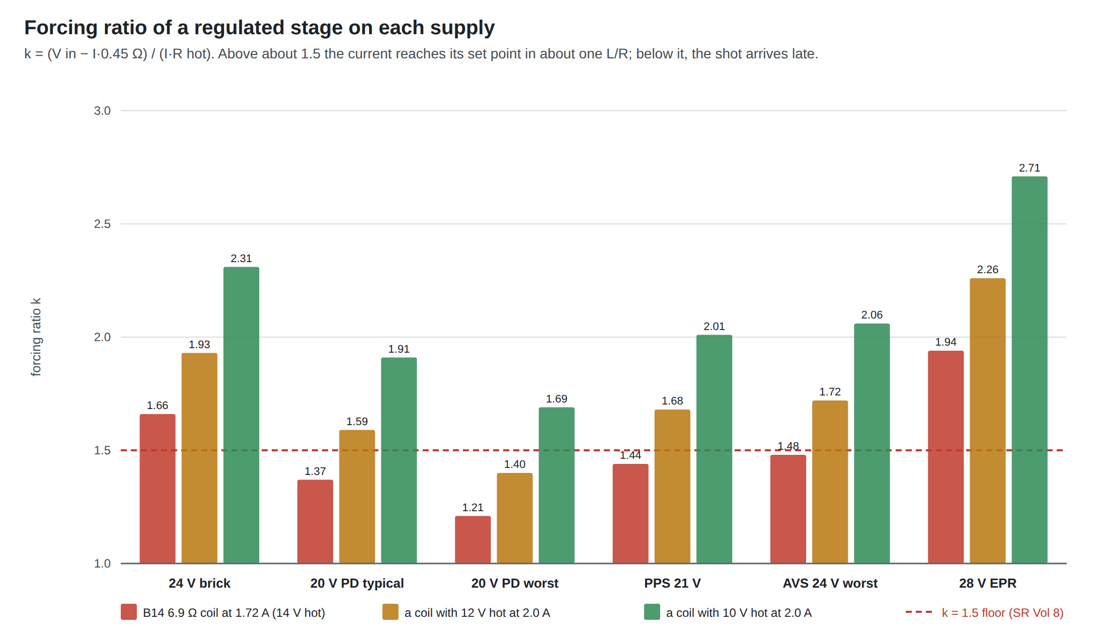
| Ledex B14 6.9 Ω at 1.72 A (14 V hot) | 1.66 | 1.37 | 1.21 |
| 12 V hot at 2.0 A | 1.93 | 1.59 | 1.40 |
| 10 V hot at 2.0 A | 2.31 | 1.91 | 1.69 |
Three readings:
- The coil Solenoid Recoil Vol 8 holds up as the example is the one coil that does not suit PD. On a 20 V contract the B14’s 6 V winding falls below 1.5 even on a typical charger; its current would arrive about 1.3 L/R after the edge instead of 0.9 L/R on the brick. The kick would still reach full strength under regulation, but late, and on the worst legal charger and cable later again (about 1.8 L/R).
- A coil chosen for PD must be on the low-resistance side of the class. Solving k = 1.5 at the worst-case 17.75 V gives a hot I·R of no more than about 11.2 V at 2 A, that is a hot resistance no higher than about 5.6 Ω; at a typical 20 V the limit is about 12.7 V, 6.4 Ω. On the brick the same limit is about 15.4 V, 7.7 Ω. The window is the same D14 window, but where the coil sits inside it now has to be decided with PD in mind.
- The 18 V floor of D14 is not quite a PD worst case. The Type-C worst case for a 20 V contract is 17.75 V at the sink (Volume 1, Section 1.8). In practice the gap is small: chargers usually sit at or above nominal, and the gun’s own shot of 2.5 A on a 3 A cable drops about 0.62 V rather than the 0.75 V the worst case assumes. But it means “20 V PD is inside the window”, as the sibling dives have it, should read “20 V PD is at the bottom edge of the window”.
So: yes, a 20 V PD charger can replace the brick, for a coil chosen with PD in mind. It is not a drop-in for any coil the brick can drive.
2.3 Does a Shot Fit Under the Contract?
Volume 1 established that a shot must stay under the contract’s operating current, because PD’s overload windows end at 10 ms and a sink may not rely on them anyway. A 60 W charger’s 20 V object is 3 A. The regulated stage draws:
- during the rise, the full set point, since the coil is connected straight across the supply until the current reaches the trip level;
- during the hold, much less, because the DRV8251A chops: it brakes for a fixed 25 µs, then drives just long enough to recover, so the supply sees the set current only for the driving fraction of each cycle.
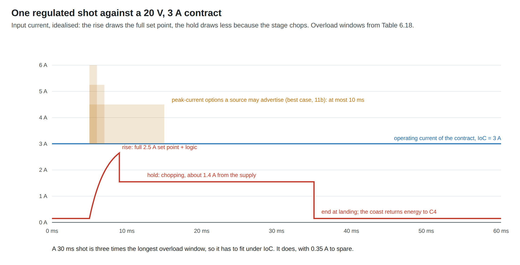
For a 2.5 A set point in a 4 Ω hot coil (10 V hot) on 20 V, the driving fraction is about 0.56, and the supply current during the hold is about 1.4 A, 28 W. For 2.0 A in 6 Ω it is about 1.3 A. The peak is the rise, at the set point plus the logic, about 2.65 A in the worst of these. One stage at 2.5 A fits under a 3 A contract with about 0.35 A to spare. D16 (the two stages never fire at once) is what makes that true; two simultaneous 2.5 A stages would not fit under any 20 V object short of a 100 W charger and a 5 A cable.
The sink controller must request an operating current to match. A Request names the current it will draw; asking for 3 A from a 3 A object is legal, and Volume 3’s picks are configured that way.
What does not fit is the reservoir’s inrush. A 1000 µF capacitor charged from 0 to 20 V at the source’s maximum slew of 30 mV/µs draws 30 A. That is why Volume 1 put the reservoir behind a soft-start switch: at 1 V/ms it draws 1 A and is full in 20 ms.
2.4 20 V Plus a Boost to 24 V
The obvious way to restore the forcing ratio is a boost converter from 20 V to 24 V. Power Supplies Vol 3 already selected a boost controller for USB-only power, the TI TPS55340, so the parts exist.
The arithmetic does not favour it. A boost delivers power, not voltage, and its input sits on the same 60 W contract:
Table 2 — The arithmetic does not favour it. A boost delivers power, not voltage, and its input sits on the same 60 W contract
| Boost efficiency | 24 V out at 2.0 A | 24 V out at 2.5 A |
|---|---|---|
| 90 % | 53.3 W in, 2.67 A from 20 V | 66.7 W in, 3.33 A from 20 V |
| 93 % | 51.6 W in, 2.58 A | 64.5 W in, 3.23 A |
At 2.5 A the boost’s input exceeds the 3 A contract during the rise, which is the one moment the boost was meant to help. At 2.0 A it fits, barely, with the logic on top. And the gain is smaller than it looks: the rise phase draws full current from the boost output, so the boost has to be sized for the pulse, not the average; it adds an inductor, a switch, a second set of losses and an EMI source in the grip; and it buys forcing ratio that a better-matched coil (Section 2.2) or a different contract (Sections 2.5 and 2.7) buys for nothing.
A boost behind a 20 V contract makes sense only if the coil chosen on the bench turns out to need more than about 12 V hot at its set current and the charger cannot offer AVS. It is kept as the fallback, not the plan.
2.5 PPS at 21 V
A charger that offers a 20 V Prog PPS object will hold any voltage from 5 to 21 V that the sink asks for (Volume 1). At 21 V the forcing ratios rise by about 5 %: 1.44 for the B14, 1.68 for the 12 V coil, 2.01 for the 10 V coil, typical. The worst case at the sink is 19.1 V, because PPS’s transient band is ±0.1 V rather than ±0.5 V.
Two properties count against PPS as the gun’s primary contract. It cannot support peak currents at all, because of its current-limit mode, and in that mode a source lowers the voltage rather than holding it if the sink exceeds its request; for a regulated stage that only means a slower rise, but it is one more behaviour to test. And the sink must re-request at least every 10 s or the charger times out, so PPS requires a sink controller that does so continuously. The better sink chips do (Volume 3). PPS is offered by many phone and laptop chargers, so it is a useful option where the charger has it; it is not something to design around.
2.6 28 V Fixed: On the Clamp
An EPR charger of the 140 W class offers 28 V at 5 A. On forcing ratio it is the best supply in the figure: 1.94 even for the B14, 2.71 for the 10 V coil. On every other count it is the worst fit for this rail.
- Its tolerance band crosses the top of the window. A 28 V contract is legal anywhere from 26.6 to 29.4 V at the source, plus 0.5 V of transient: up to 29.9 V at the sink (Volume 1, Section 1.8).
- The input TVS sits there. D33 chose the SMBJ28A because its 28 V stand-off equals the top of the window; the LiPo Batteries dive notes a minimum breakdown of 31.1 V from distributor listings, not yet confirmed against the maker’s sheet. A rail held at up to 29.9 V is above the stand-off, so the TVS leaks more than its data sheet’s stand-off figure promises, though it should not yet conduct in earnest.
- The coast pushes it over. The regulated stage returns about 0.06 J to the reservoir at the end of every shot. From 29.9 V into 1000 µF that is a rise to about 31.8 V, into the TVS’s breakdown range, at up to eight times a second in autofire. The TVS would absorb part of every coast. The DRV8251A’s 50 V absolute maximum is still safe; the clamp is not designed to be worked that way.
- It needs the most infrastructure: an EPR charger, an EPR cable (or a captive one), an EPR-capable sink controller and its keep-alive.
28 V is usable for a gun that adds headroom above the clamp, which means revisiting D33. On the rail as decided, it is the contract to avoid. The same applies with more force to 36 and 48 V, which are outside the window altogether and would need a buck stage.
2.7 EPR AVS at 24 V: the Contract That Matches the Brick
Every EPR source must offer an AVS object in its extended capabilities (Volume 1, Section 1.6), and a 140 W source’s covers 15 to 28 V in 100 mV steps. A sink can therefore ask an EPR charger for 24.0 V.
That contract has the brick’s own forcing ratios, within the ±5 % source tolerance: worst case at the sink 21.55 V, where the B14 is at 1.48, the 12 V coil at 1.72 and the 10 V coil at 2.06. Its top, 25.7 V, leaves 2.3 V below the SMBJ28A’s stand-off, and the coast lifts it by about 2.2 V into 1000 µF, to 27.9 V, still under the stand-off; the brick at a nominal 24 V ends at about 26.4 V. The coil chosen for the brick works unchanged. The current available is up to 5 A at 24 V, enough for both stages at once if D16 is ever revisited.
The price is the same infrastructure as 28 V: an EPR charger of at least 100 W, an EPR cable or a captive cable, an EPR sink with AVS support and its keep-alive. Volume 3 shows that the cheapest EPR sink chips request AVS only over I2C, which puts a few registers’ worth of PD into the gun’s firmware or into a small dedicated microcontroller.
AVS at 24 V is the PD contract this dive recommends for a gun that should behave exactly as it does on the brick. 20 V fixed is the contract it recommends for a gun that should run from an ordinary laptop charger, with the coil chosen accordingly.
2.8 Which Chargers Offer What
Volume 1’s power rules say what a compliant charger must offer. What chargers actually advertise has to be read from a test of each one. The most useful public source is ChargerLAB’s measured capability lists; its June 2023 survey of PD 3.1 chargers recorded:1
Table 3 — 2.8 Which Chargers Offer What
| Charger | Port | Advertised fixed objects | 28 V? |
|---|---|---|---|
| Apple 140 W (A2452) | single | 5.2 V 3 A, 9 V 3 A, 15 V 5 A, 20.5 V 5 A, 28 V 5 A | yes |
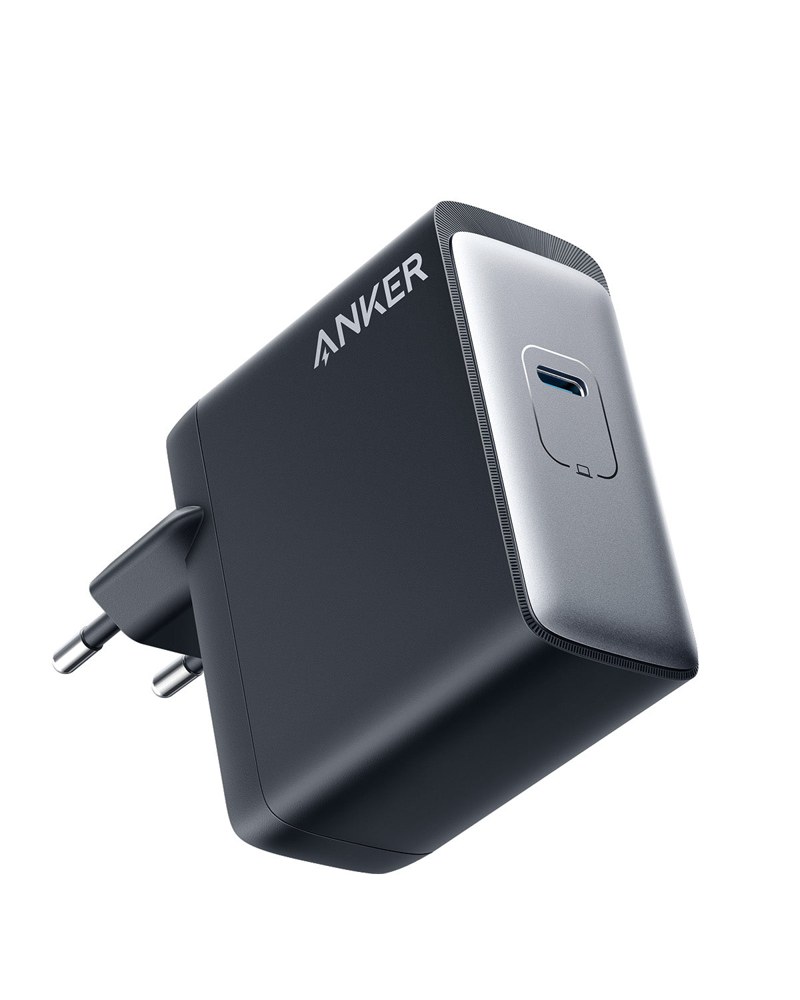
| Anker 717 140 W (A2341) | single | 5 V 3 A, 9 V 3 A, 15 V 3 A, 20 V 5 A, 28 V 5 A | yes |
| UGREEN 140 W (CD289) | C1 only | 5, 9, 12, 15 V 3 A; 20 V 5 A; 28 V 5 A | C1 only |
| SHARGE S140 | C1 only | 5, 9, 12, 15 V 3 A; 20 and 28 V 5 A | C1 only |
| MOMAX UM27CN 140 W | C1 only | 5, 9, 12, 15 V 3 A; 20 V 5 A; 28 V 5 A | C1 only |
| Baseus CCGAN140CS | C1 only | 5, 9, 12, 15 V 3 A; 20 V 5 A; 28 V 5 A | C1 only |
| AOHi AOC-C012 140 W | per port | 5, 9, 12, 15 V 3 A; 20 V 5 A; 28 V 5 A; PPS 3.3–21 V 5 A | yes |
Anker’s own product page for the A2341 confirms its list, “5V==3A /9V==3A /15V==3A /20V==5A / 28V==5A (140W Max)”, and adds “PD 4.0, PPS”.2 Its EU product page showed it as sold out on 19 October 2026.
Four points from that table and its sources.
- Every one of them stops at 28 V. The 140 W class is the 28 V class (Table 3.5 of the specification). None of the survey’s chargers advertises 36 or 48 V. One that does is Framework’s 180 W adapter, which reaches “up to 36V/5A” with a Weltrend WT6676F controller; Framework’s own note is the clearest statement of the cable rule anywhere: “Remember to use a USB-C cable that supports EPR voltages, otherwise you’ll be limited to 20V/3A or 20V/5A.”3
- No AVS object appears in any of the 2023 lists, although the current specification requires one from every EPR source. Either the survey omitted augmented objects or those early PD 3.1 chargers predate the requirement in practice. Whether a given charger will grant a 24.0 V AVS request is therefore a bench test (Volume 6, test T1), not something to assume from its wattage.
- Multi-port chargers give 28 V on one port only, and share power when more than one port is in use. A gun on a multi-port charger should be the only thing plugged in.
- Apple’s “20 V” is 20.5 V. That is within the ±5 % rule and is worth about 3 % of forcing ratio. Measured objects differ from nominal, which is another reason to read a charger’s capabilities on the bench rather than from its label.
For the 20 V route the charger can be almost any laptop charger rated 60 W or more. The specification guarantees its 20 V object at 3 A. A 65 W charger offers 3.25 A only over a 5 A cable, which the gun does not need.
2.9 When the Charger Cannot Give What Was Asked
The worst failure is not a charger that refuses. It is a charger that quietly gives less.
A sink set for 20 V and plugged into a 45 W charger finds no 20 V object. What happens next is decided inside the sink controller, and the chips differ (Volume 3): ST’s STUSB4500 settles for a 5 V contract if no configured voltage matches exactly; Hynetek’s HUSB238A “loops through the PD source PDOs from highest voltage first” and takes the first one at or below its target, so it would settle for 15 V; sellers of cheap 28 V trigger boards say the same in their own words, that the board is “provided the next lowest voltage”.45
A 15 V rail is 13.0 to 16.25 V at the sink. Under regulation the coil still reaches its set current if 15 V is above its hot I·R, but with a forcing ratio near 1; it reaches it late or never. Worse, the gun cannot tell from the kick alone. Whatever sink is used, the rail must not be connected unless the contract is one the design accepts. In hardware, that means the load switch closes only on a contract at or above 18 V (Volume 3 shows which chips do this natively). In firmware, it means reading the rail before enabling the solenoid output, which the Pico can do with one divider into a spare ADC pin if the pin budget allows, or by reading the sink controller’s status over I2C.
The same logic applies to a hard reset in the middle of play. The rail drops to 0 and returns at 5 V before the sink renegotiates; for that second the stage must be disabled, not driven from 5 V.
2.10 Why This, and Why Not the Others
Table 4 — 2.10 Why This, and Why Not the Others
| Contract | Verdict | Why | Why not the others |
|---|---|---|---|
| 20 V fixed, 3 A, from a ≥ 60 W charger | Proposed for a gun on an ordinary laptop charger | Every charger over 45 W must offer it; one stage at 2.5 A fits under 3 A; no EPR cable or keep-alive | Forcing ratio 1.37 to 1.21 for the B14; needs a coil of ≤ about 5.6 Ω hot at 2 A |
| EPR AVS at 24.0 V | Proposed for a gun that should behave as on the brick | Same forcing ratio and clamp margin as the brick; 5 A available | Needs an EPR charger, an EPR or captive cable, an AVS-capable sink and I2C; AVS support on real chargers unverified |
| PPS at 21 V | Use where offered, do not design around | 5 % more headroom than 20 V; tight ±0.1 V band | Optional in chargers; no peak current; current-limit mode; 10 s re-request |
| 20 V plus boost to 24 V | Fallback only | Restores forcing ratio on any 60 W charger | Over 3 A input at a 2.5 A set point; an inductor and switcher in the grip; a coil choice does it for free |
| 28 V fixed | Rejected on the D14 rail | Most forcing ratio | Up to 29.9 V at the sink, over the SMBJ28A stand-off; coast reaches about 31.8 V; EPR infrastructure |
| 36 V and 48 V | Rejected | — | Outside the window; would need a buck stage and new clamps |
| 15 V and below | Rejected | — | Below 18 V; a forcing ratio near 1 for any useful coil |
The proposed rows for the decision log are in Volume 6. Neither proposal changes D14 or D17: the first gun still runs from the brick.
Sources
Footnotes
-
ChargerLAB, “Top Chargers Recommended for PD 3.1 Fast Charging Standard”, 7 June 2023, https://www.chargerlab.com/top-chargers-recommended-for-pd-3-1-fast-charging-standard/ (read 2026-10-19). Third-party test lab; capability lists as measured or published at the time. ↩
-
Anker, “Anker 717 Charger (140W)” product description (A2341), https://service.anker.com/product-description/a085g000004zRHiAAM/anker-717-charger-140w (read 2026-10-19); product photo and EU availability from https://www.anker.com/eu-en/products/a2341 (read 2026-10-19). ↩
-
N. Patel, Framework, “Framework Laptop 16 Deep Dive – 180W Power Adapter”, 7 June 2023, https://frame.work/blog/framework-laptop-16-deep-dive---180w-power-adapter (read 2026-10-19). ↩
-
Hynetek, HUSB238A data sheet, Rev. 1.1, section “RDO in GPIO Mode”. Copy: https://atta.szlcsc.com/upload/public/pdf/source/20250807/BD7DDAA8DFA1B07F0B3606C6A260D6C7.pdf (read 2026-10-19). ↩
-
Seller listing text for a four-pack of 140 W PD 3.1 trigger boards on Newegg (seen in a search result, 2026-10-19): “if the power supply does not support the requested voltage, it will be provided the next lowest voltage”. The chip on those boards is not identified. ↩
Comments (0)