USB-C Power Delivery · Volume 1
How USB Power Delivery Works — Contracts, Voltages and the Rules a Sink Must Keep
Source capabilities, fixed and programmable objects, the extended power range, what a charger of each wattage must offer, the limits a sink accepts in return, and the voltage that actually arrives at the gun
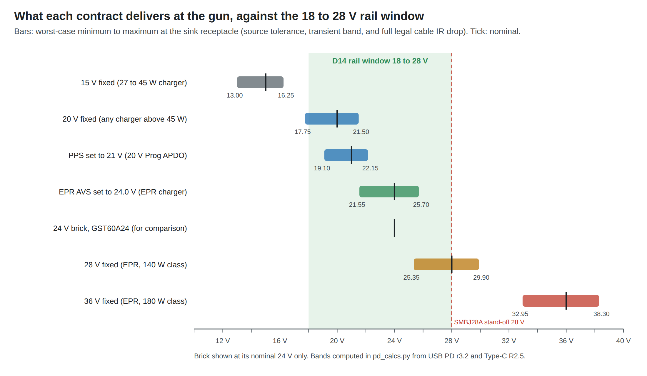
1.1 What Power Delivery Could Buy a Light Gun
The recoil rail is decided: 24 V class, working from 18 to 28 V, with the solenoid current regulated by a DRV8251A stage and the recoil and ejection-port stages never firing together (decisions D13, D14 and D16; Solenoid Recoil Vol 8, Reference Electronics Vol 5). The supply for the first wired gun is decided too: a GST60A24-class brick, with no USB-only stage in between (D17; Power Supplies Vol 6).
USB Power Delivery is the one way a commodity USB-C charger, the kind already in most houses, can feed that rail. Plain USB cannot: the most a Type-C port promises without PD is 5 V at 3 A, 15 W, and Power Supplies Vol 3 has already shown why 15 W only works through storage and fades in autofire. PD raises the voltage instead of the current, to 20 V at up to 3 A on any ordinary cable, and to 28 V and beyond with the extended power range. The Solenoid Recoil dive chose the rail window partly so that “a 20 V USB PD contract at somewhat reduced forcing” would fit inside it.
This dive owns the rest of that sentence: how PD works in enough depth to design a sink, which chargers actually offer which voltages, which sink controller to use and why, whether a PD charger can stand in for the brick, how PD would coexist with the one-GX-connector decision at the gun (D31), and how to measure it all on the bench. This first volume is the protocol. It is written for an electronics engineer who has never needed to know what is on the CC wire.
1.2 The Wires: VBUS, CC, and a Data Pair PD Never Touches
A USB 2.0 Type-C receptacle carries four kinds of signal that matter here: VBUS and GND (four pins each, in parallel), the two configuration-channel pins CC1 and CC2, and the USB 2.0 data pair D+ and D−, duplicated top and bottom so the plug can go in either way up. The SuperSpeed pairs and the sideband pins are unused by a USB 2.0 device such as an RP2040, which runs USB 1.1 full speed.
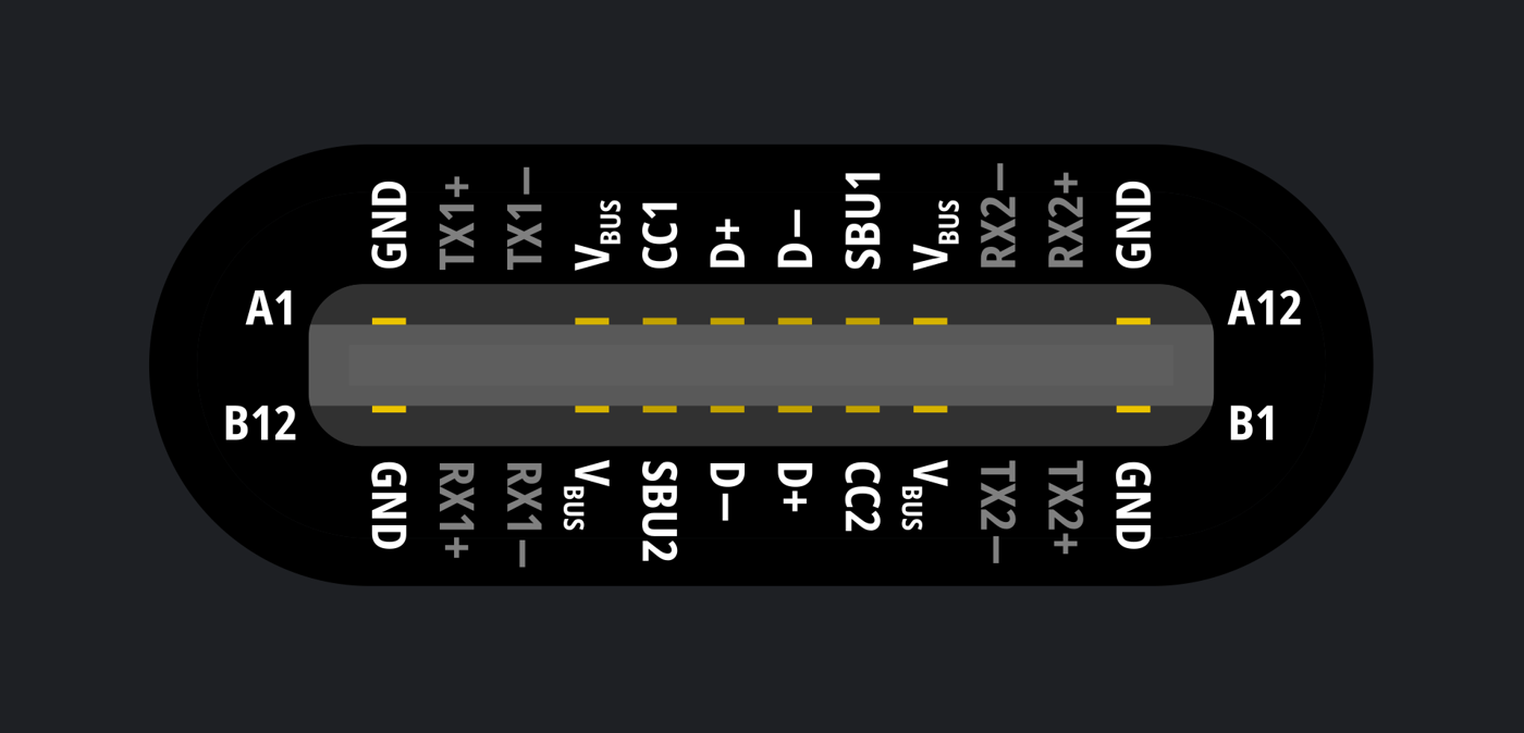
The division of labour is complete. PD talks only on CC. Its messages are biphase-mark-coded (BMC) on the CC wire at about 300 kbit/s; a cable connects one CC conductor end to end, and the receptacle’s other CC pin becomes VCONN to power an electronically marked cable’s chip. USB data runs only on D+ and D−, exactly as on a micro-B port. A light gun can therefore have a PD controller negotiating 20 V on CC while the RP2040 enumerates as a HID device on the data pair, and neither knows the other exists.
One trap follows, and it recurs in Volume 3. Several cheap sink chips also speak the legacy fast-charge protocols, BC1.2, Apple’s divider and Qualcomm QC, and those signal on D+ and D−. WCH’s CH224 parts and Hynetek’s HUSB238A both have DP and DM pins for exactly that purpose.12 On a power-only board that is harmless. On a gun, the data pair belongs to the RP2040, and a chip that drives or loads it to talk to a charger is a chip that can break enumeration. The rule for every design in this dive is simple: the PD chip connects to CC and VBUS; D+ and D− go to the microcontroller and nowhere else.
1.3 A Contract in Five Messages
Before any message, Type-C itself decides who is who. The source (a charger) has a pull-up, Rp, on CC; the sink (the gun) has a pull-down, Rd, of 5.1 kΩ. When the source sees Rd it turns VBUS on at 5 V, called vSafe5V in the specification. The level of the pull-up advertises 0.5/0.9, 1.5 or 3 A at 5 V; Power Supplies Vol 3 covers that layer and the currents it allows.
PD is a conversation on top of that, and a normal one is five messages long:
- Source_Capabilities. The source lists what it can supply as up to seven power data objects (PDOs): for example “5 V 3 A, 9 V 3 A, 15 V 3 A, 20 V 3 A”, optionally followed by programmable objects (Section 1.5).
- GoodCRC. Every message is acknowledged at the protocol layer; these acknowledgements are omitted from here on.
- Request. The sink names one object by its position and states the current it will draw (the operating current) and the most it might need.
- Accept. The source agrees, then ramps VBUS to the new voltage. The specification limits the slew to 30 mV/µs in either direction, and during the transition the sink may draw no more than 500 mA (iSnkStdby).34
- PS_RDY. The source reports that the new voltage is stable. From that moment there is an explicit contract, and the sink may draw its operating current.
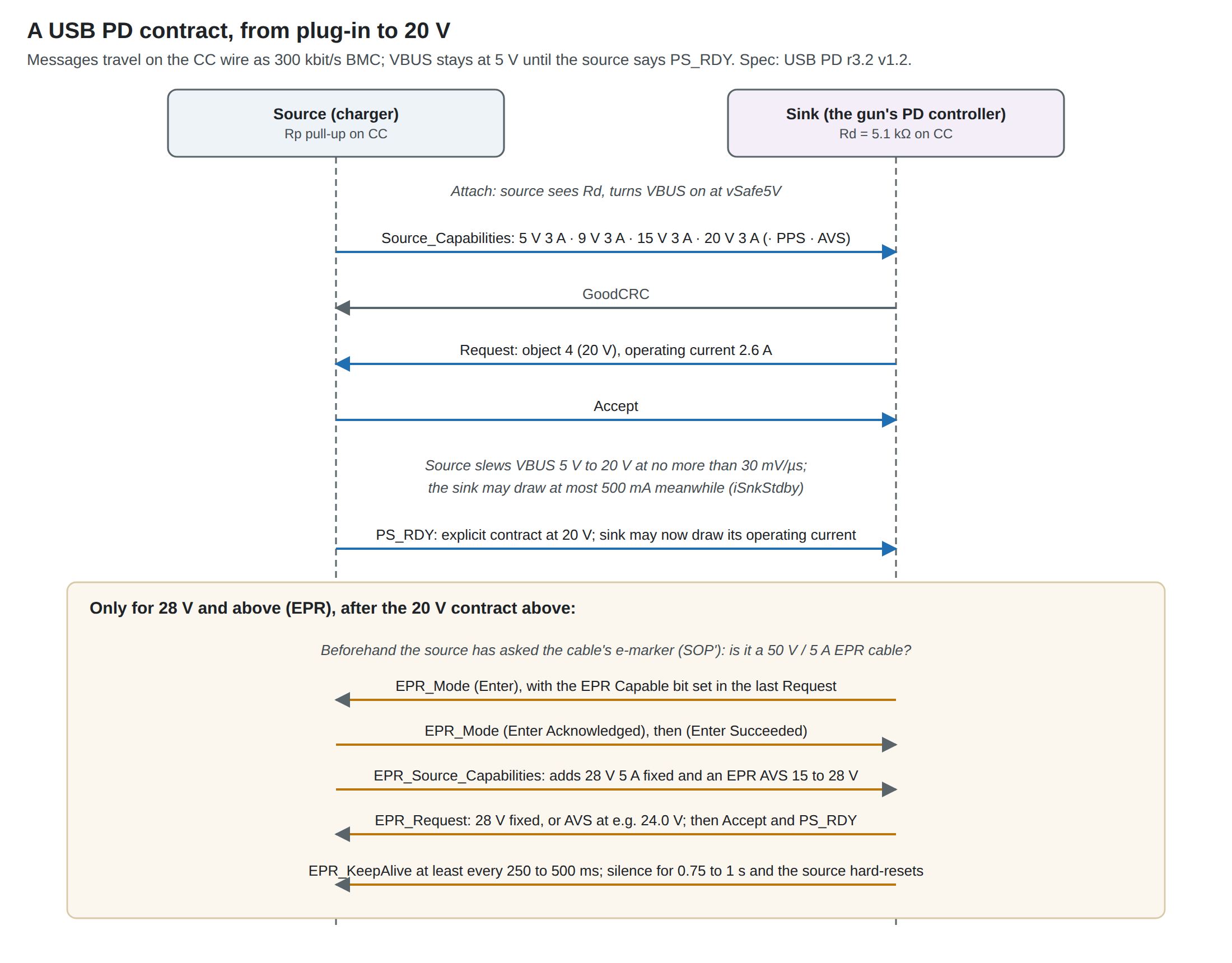
Three properties of that exchange matter to a gun.
Nothing changes until the sink asks. A charger leaves VBUS at 5 V forever if the sink says nothing. That is why every PD “decoy” or “trigger” board exists: a small chip whose only job is to send a Request.
The sink chooses from a menu; it cannot order off it. A fixed request is for one of the listed voltages. If the gun wants 20 V and the charger’s list stops at 15 V, there is no 20 V to be had, and what the sink controller does next (refuse, settle for 15 V, or fall back to 5 V) differs from chip to chip. Volume 3 shows that the difference is a design decision with a safety consequence.
Either side can reset everything. A Hard Reset, sent by either end on a protocol error or a missed timer, makes the source drop VBUS to 0 V and come back at 5 V; the sink has 15 ms to prepare for it (tSnkHardResetPrepare) and the whole recovery takes on the order of a second.4 A gun whose logic is powered from the same VBUS will brown out. A gun whose logic is powered from the PC’s USB, as in the wired design, only loses its recoil rail for that time.
1.4 What a Charger Must Offer, by Wattage
The PD specification does not leave a charger’s menu to the manufacturer. Its power rules fix which fixed voltages a source must offer for a given maximum output, the Port Maximum PDP. Table 3.1 of the current revision (r3.2 version 1.2, August 2026) reads:5
Table 1 — 1.4 What a Charger Must Offer, by Wattage
| Charger’s maximum (Port Maximum PDP) | 5 V | 9 V | 15 V | 20 V |
|---|---|---|---|---|
| up to 15 W | PDP ÷ 5 | — | — | — |
| over 15 to 27 W | 3 A | PDP ÷ 9 | — | — |
| over 27 to 45 W | 3 A | 3 A | PDP ÷ 15 | — |
| over 45 to 100 W | 3 A | 3 A | 3 A | PDP ÷ 20 |
Three consequences settle questions the rest of this dive depends on.
- A charger offers 20 V only above 45 W. A 30 W phone charger tops out at 15 V; a 45 W charger also tops out at 15 V, at 3 A. “Any USB-C charger” is not a 20 V source. For the gun, the floor is a charger rated over 45 W, and in practice 60 W or more, because a 60 W charger is the first whose 20 V object carries 3 A.
- More than 3 A needs a 5 A cable. A 65 W charger’s 20 V object is 3.25 A, and a 100 W charger’s is 5 A, but “currents > 3A assume the Cable VBUS Current Carrying Capability is capable of the Port Maximum PDP”; with an ordinary 3 A cable the source limits itself.5 Volume 5 covers cables.
- 12 V is not a PD voltage any more. The specification now says “A Source Shall Not Advertise an optional Fixed PDO voltage > 9V”.5 Many chargers still list 12 V, a habit from the PD 2.0 era, and several trigger boards offer it; a design that depends on 12 V depends on the charger ignoring the current rules. The gun’s rail never asks for it.
The specification also keeps optional objects out of the high-power class: “EPR Capable Sources Shall Not implement optional Fixed PDOs.”5 Published test lists of 140 W chargers nevertheless still show 12 V on several of them (Volume 2), which is a reminder that a measured capability list beats a rule about what it should contain.
1.5 PPS and AVS: Asking for a Voltage Instead of Picking One
Fixed objects are a menu of four. Two kinds of augmented object (APDO) let the sink name a voltage inside a range.
Programmable Power Supply (PPS) is optional. A source that offers it advertises a range and a current; the sink requests a voltage in 20 mV steps, and the source holds it within ±5 %. The ranges are set by Table 4.2: the “9 V Prog” object covers 5 to 11 V, the “15 V Prog” 5 to 16 V and the “20 V Prog” 5 to 21 V.6 PPS was built to charge phone batteries directly, and it has two behaviours a gun must respect. First, it has a current-limit mode: if the sink draws more than it asked for, the source lowers the voltage rather than tripping, down to a shutdown threshold near the bottom of the range. Second, the sink must re-request at least every 10 s (tPPSRequest), or the source times out in 12 to 15 s and resets.7 And “A Source operating in PPS Mode cannot support peak currents, due to the CL requirements.”8
For a gun the interesting number is the top of the 20 V range: 21 V is a legal PPS request, 5 % more forcing than a fixed 20 V contract from the same charger, if the charger offers PPS at all.
Adjustable Voltage Supply (AVS) is the newer object, added for systems that want a steady voltage rather than a battery-charging ramp. It steps in 100 mV, holds ±5 % and has no current-limit mode. In the standard power range it covers 9 to 15 V or 9 to 20 V (and only where the 15 V fixed object exists); in the extended range it covers 15 V up to 28, 36 or 48 V.6 TI’s summary puts the difference neatly: PPS is a voltage that “will constantly change over time” as a battery charges, while AVS “is intended to be a constant supply that provides a system input voltage to a voltage level closer to what the system requires as a whole.”9
That second sentence describes a light gun’s recoil rail exactly. Volume 2 shows that an AVS request for 24.0 V is the closest thing to a 24 V brick that USB can deliver.
1.6 The Extended Power Range: 28, 36 and 48 V
Everything up to 100 W is the standard power range (SPR). The extended power range (EPR) adds fixed objects at 28, 36 and 48 V at up to 5 A, for chargers whose maximum is over 100 W and up to 240 W. Table 3.5 sets them by wattage: a 100 to 140 W charger offers 28 V; 140 to 180 W adds 36 V; 180 to 240 W adds 48 V; each also offers EPR AVS up to its top voltage.5 A 140 W laptop charger is therefore a 28 V source, and nothing above it.
EPR is not something a sink simply requests. Section 7.30.1 lists the conditions, all of which must hold:10
- the source must have verified that the cable is EPR-capable, by reading its electronic marker;
- the sink must not be connected through a charge-through dongle;
- source and sink must already have an SPR explicit contract;
- the source must have set the EPR Capable bit in its 5 V object, and the sink must have set it in its last Request;
- the sink then sends an EPR_Mode (Enter) message, and the two exchange acknowledgements before the source sends its extended capabilities.
Two more rules keep it safe. The source checks the cable on its own: “When the Attached cable is not an EPR Capable cable, an EPR Capable Source Shall only operate in SPR Mode.” And once in EPR mode the sink must keep talking: it sends EPR_KeepAlive whenever it has been silent for 250 to 500 ms, and if the source hears nothing for 0.75 to 1 s it initiates a hard reset.7 A 28 V gun therefore needs a live PD controller for as long as it is plugged in. That is no burden for the chips in Volume 3, but it rules out any idea of negotiating once and then switching the controller off.
The EPR cable itself is a defined thing. The Type-C specification requires that EPR cables “functionally support a reported 50 V and 5 A operation”, be electronically marked, and carry the EPR Mode Capable bit; components in the VBUS path of such a cable should be rated for 63 V.11 For a device with a captive cable, the PD specification makes the device answer for its own cable: “EPR Sinks with a captive cable Shall report 50V.”12 That is the route by which a cheap 28 V trigger board can work with an ordinary charger: WCH’s CH224 manual says that to request more than 20 V or more than 60 W through its e-marker emulation, the board must carry a Type-C plug, not a receptacle.1 Volume 5 returns to what that means for the gun’s cable.
One last rule makes EPR more useful than it first looks. Every EPR source’s extended capabilities message must include an AVS object: “One EPR AVS APDO Shall be sent.”13 A compliant 140 W charger can therefore deliver any voltage from 15 to 28 V in 100 mV steps, including 24.0 V. Whether every 140 W charger on sale does so in practice is a bench question (Volume 6), because the published capability lists for several early ones do not show an AVS object.
1.7 What the Sink Promises in Return
A PD sink is not just a load that happens to be on VBUS. The specification’s sink parameters, Table 4.7, put real constraints on a recoil design:4
Table 2 — 1.7 What the Sink Promises in Return
| Parameter | Limit | What it means for the gun |
|---|---|---|
| cSnkBulkPd | 100 µF maximum on VBUS after a contract | The DRV8251A board’s 1000 µF reservoir cannot sit directly on VBUS |
| cSnkBulk | per the USB 2.0/3.x rules (10 µF) at attach | Before negotiation the receptacle must look nearly unloaded |
| iLoadStepRate | 150 mA/µs | A coil’s current rises at V/L, far slower; a stiff capacitor charging through a switch is not |
| iSnkStdby | 500 mA during a voltage change | The coil must not fire while the voltage is moving |
| tSnkHardResetPrepare | 15 ms | Time to get off the bus before VBUS is dropped |
| vSprMax | 24 V | ”A Sink Should tolerate this VBUS voltage without damage” even on an SPR contract |
The specification also says what to do about the capacitance limit: “Capacitance beyond the cSnkBulk or cSnkBulkPd limit is permitted provided it is isolated from VBUS through current-limiting circuitry … The Sink Shall discharge this additional capacitance and Shall remove it in the event of a disconnect, Hard Reset, Fast Role Swap, or Power Role Swap.”14
So the reservoir goes behind a switch that limits inrush, opens on reset and detach, and, for a recoil stage, blocks reverse current. The last requirement comes from the regulated stage itself. In coast, the DRV8251A returns the coil’s stored energy, about 0.06 J, to its supply (Reference Electronics Vol 5). Into 1000 µF that is a rise of about 2.5 V. Into 100 µF it would be a rise from 20 V to about 41 V (pd_calcs.py), which is over every voltage rating on the input. A charger cannot sink current any more than a brick can, so the energy must stay on the gun’s side of the switch. Volume 3 picks the parts that do this.
1.8 The Voltage That Actually Arrives
A “20 V” contract is a tolerance band, and the gun sees the far end of a cable. Three specifications stack:
- The source holds a fixed object within ±5 % at its receptacle (vSrcNew), and may move a further ±0.5 V during transients (vSrcValid).3
- A compliant cable may drop up to 500 mV on VBUS and 250 mV on ground at its rated current, including contact resistance.15
- The Type-C specification combines them for the sink: the minimum valid voltage is vNew(min) − 750 mV + vValid, where “750 mV = 500 mV + 250 mV (maximum IR drop)”.16
For a 20 V contract that is 19.0 − 0.75 − 0.5 = 17.75 V, below the 18 V floor of the D14 window. For the other contracts a gun might use:
The worst case is a worst case: it assumes a charger at the bottom of its tolerance, a transient, and a cable passing its full rated current. Real chargers usually sit at or above nominal (Apple’s 140 W adapter is listed at 20.5 V for its “20 V” object, Volume 2), and a shot at 2.5 A on a 3 A cable drops about 0.62 V rather than 0.75 V. But the band explains two things the rest of the dive builds on: a 20 V contract is at the bottom edge of the window, not comfortably inside it, and a 28 V contract is at the top edge, where the input TVS chosen in D33 begins to matter. The middle of the window is reachable only by PPS at 21 V or by EPR AVS.
1.9 Peak Current, and Why a Shot Must Fit Under the Contract
A solenoid draws its current in pulses, so the question every recoil designer asks of a supply is whether it tolerates a peak above its rating. Bricks answer it in their trip band (Power Supplies Vol 2). PD answers it in two bits of each fixed object, the Peak Current field, defined in Table 6.18:8
Table 3 — 1.9 Peak Current, and Why a Shot Must Fit Under the Contract
| Field | Overload a source must tolerate |
|---|---|
| 00b | none: peak equals the operating current |
| 01b | 150 % for 1 ms at 5 % duty; 125 % for 2 ms at 10 %; 110 % for 10 ms at 50 % |
| 10b | 200 % for 1 ms; 150 % for 2 ms; 125 % for 10 ms at 50 % |
| 11b | 200 % for 1 ms; 175 % for 2 ms; 150 % for 10 ms at 50 % |
The field exists for laptops with short bursts of activity, it is “intended for direct Port to Port connections only”, and a sink that uses it “Shall also function correctly when Attached to a Source that does not offer the Peak Current capability”.8 Two conclusions follow for a gun.
First, no overload window is longer than 10 ms, and a recoil shot is 10 to 45 ms. Even a charger advertising the best case cannot be asked to carry a shot above its operating current. Second, a sink may not rely on the field at all. A light gun on PD must therefore draw its pulse under the operating current of the contract.
Under regulated drive, it does. The DRV8251A stage draws its set current only while the current rises; while it holds, it chops, and the supply sees roughly the set current times the coil’s share of the rail. Volume 2 works the numbers: a 2.5 A shot from a 20 V, 3 A contract peaks at about 2.65 A including the logic, under the 3 A operating current, and averages far less. That is the reverse of the brick case, where the pulse had to be kept below the bottom of a trip band; with PD it has to be kept below a number the gun itself requested.
Sources
Footnotes
-
WCH (Nanjing Qinheng Microelectronics), CH224 手册1 (CH224 manual 1), version 2.1, Chinese. Copy on LCSC’s attachment server, https://atta.szlcsc.com/upload/public/pdf/source/20250227/6D68A1393FFD6E9F0B2393231A5DDBA5.pdf (read 2026-10-19). Pin tables 4-1 and 4-2 (DP, DM as “USB 总线”, the USB bus); §2 features (BC1.2 and other fast-charge protocols); §5.3 e-marker emulation: requests above 20 V or 60 W need a Type-C plug and 1 kΩ from CC2 to ground. ↩ ↩2
-
Hynetek, HUSB238A USB PD EPR Sink Controller data sheet, Rev. 1.1 (January 2025). Copy on LCSC’s attachment server, https://atta.szlcsc.com/upload/public/pdf/source/20250807/BD7DDAA8DFA1B07F0B3606C6A260D6C7.pdf (read 2026-10-19). Features: “Automatic Legacy Protocols Detection Including BC1.2, Divider 3, QC2.0”; pin 1 “D+ … Positive line of the USB data line pair”. ↩
-
USB Implementers Forum, Universal Serial Bus Power Delivery Specification, Revision 3.2, Version 1.2 (August 2026), §4.7.1 source parameters: vSrcNew (fixed supply, PDO voltage × 0.95 to × 1.05), vSrcValid (±0.5 V), vSrcSlewPos and vSrcSlewNeg (30 mV/µs). https://www.usb.org/document-library/usb-power-delivery (downloaded 2026-10-19). ↩ ↩2
-
Ibid., Table 4.7, Sink Electrical Parameters: cSnkBulkPd 100 µF, iLoadStepRate 150 mA/µs, iSnkStdby 500 mA, tSnkHardResetPrepare 15 ms, tSnkRecover 150 ms, vSprMax 24 V. ↩ ↩2 ↩3
-
Ibid., §3.2 power rules: Table 3.1 (SPR source voltages and minimum currents by Port Maximum PDP) and its note 1; §3.2.5.1 optional voltages, rules 1 and 5; Table 3.2 note 2 (”> 60W Port Present PDP requires a 5A cable”); Table 3.5 (EPR source capabilities by Port Maximum PDP). ↩ ↩2 ↩3 ↩4 ↩5
-
Ibid., Table 3.4 (SPR PPS APDOs), Table 4.2 (PPS voltage ranges: 9 V Prog 5–11 V, 15 V Prog 5–16 V, 20 V Prog 5–21 V), Table 4.3 (SPR AVS 9–15 V and 9–20 V), Table 4.4 (EPR AVS 15–28, 15–36, 15–48 V); vPpsStep 20 mV. ↩ ↩2
-
Ibid., Chapter 6 timer table: tSinkEPRKeepAlive 250–500 ms, tSourceEPRKeepAlive 750–1000 ms, tPPSRequest 10 s maximum, tPPSTimeout 12–15 s. ↩ ↩2
-
Ibid., §4.1.6 Source Peak Current Operation; §4.2.8 Sink Peak Current Operation; §6.4.1.3.13 and Table 6.18, PDO Peak Current. ↩ ↩2 ↩3
-
A. McGaffin, Texas Instruments, “USB Type-C® and USB Power Delivery: Designing for both Extended Power Range and battery-powered systems”, technical article SSZTD49A, September 2024, revised October 2024, https://www.ti.com/lit/SSZTD49 (read 2026-10-19). ↩
-
Ibid., §7.30.1 Process to Enter EPR Mode; §3.2.5.3 EPR rule 5. ↩
-
USB 3.0 Promoter Group, USB Type-C® Cable and Connector Specification, Release 2.5 (March 2026), §2.4 and §3.11.1–3.11.2. https://www.usb.org/document-library/usb-type-cr-cable-and-connector-specification-release-24 (downloaded 2026-10-19). ↩
-
Ibid., cable VDO “Maximum VBUS Voltage” field: “EPR Sinks with a captive cable Shall report 50V.” ↩
-
Ibid., §6.5.18 EPR_Source_Capabilities Message. ↩
-
Ibid., §4.2 (sink bulk capacitance), text following the sink capacitance figure. ↩
-
Ibid., §4.4.1 IR Drop. ↩
-
Ibid., Table 4-3, VBUS Sink Characteristics, vSinkPD_min. ↩
Comments (0)