M40A1 — the Marine Sniper Rifle, and a Clone · Volume 4
How the Remington 700 Works
A turned receiver, a two-lug bolt with a recessed face, a clip extractor, cock-on-opening, and three generations of trigger
Every M40 was a Remington Model 700 short action with Marine work on top. The Corps said so in its own procurement: a 2009 notice for M40A5 support listed 89 Remington brand-name parts, from firing-pin assemblies and bolt bodies to extractors, trigger assemblies and receivers, and stated that the rifle “was developed, tested and certified using specific parts from specific manufacturers”.1 Anyone maintaining, repairing or building an M40-pattern rifle is therefore maintaining, repairing or building a Model 700.
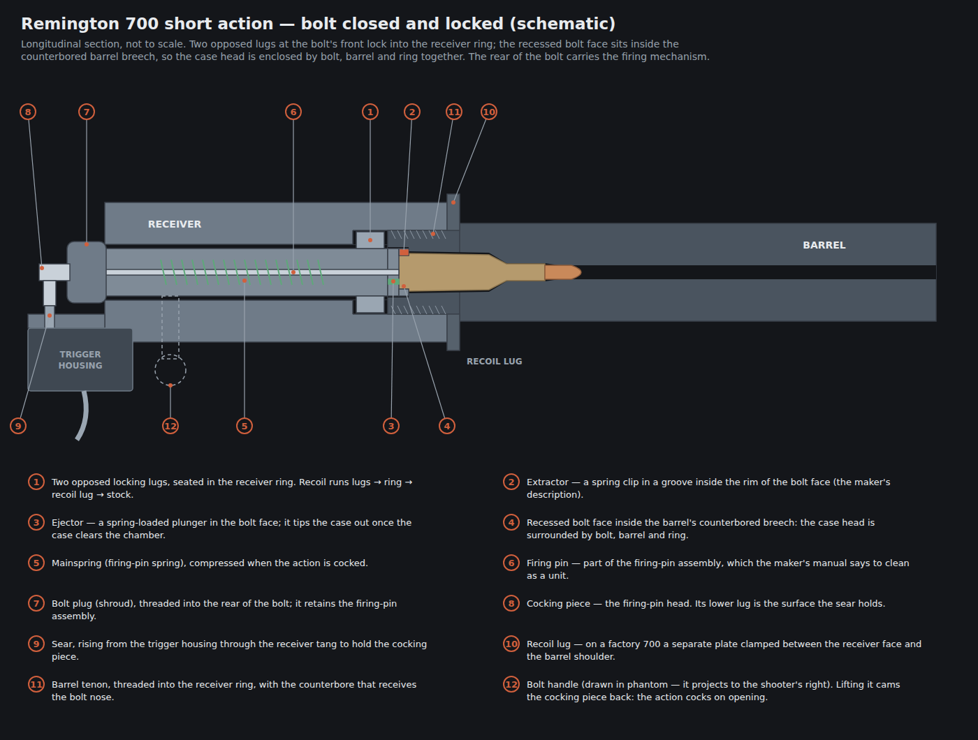
This volume describes how the action works — its parts, what each does, and the cycle of operation — at the depth an experienced gunsmith needs to diagnose it. Volume 5 takes it apart; Volume 6 covers what goes wrong. The description is built from Remington’s own owner’s manual and product pages, the reference literature on the design, and the visible construction of the action. No Remington dimensioned drawing was available, so the diagrams here are schematics and are labelled as such.
4.1 Where the Design Came From
The Model 700 was introduced in 1962 and designed by Merle “Mike” Walker, per Remington’s own history page.2 It was not a clean sheet. American Rifleman’s history of the rifle: “Tinkering with the Model 30 design, Mike Walker’s developments were released by Remington in 1947 as the Model 721”, and the 700 “still used several important elements from Walker’s previous work, but in a refreshed outline with much tighter internal tolerances”.3
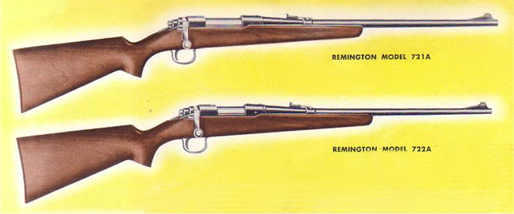
The reference literature summarises the idea behind the 721 and its short-action sibling the 722: a cylindrical receiver made from round bar stock that could be turned on a lathe, rather than a forged receiver shaped by a long series of milling operations, together with stamped small parts, all to reduce the cost of making a precise rifle.4 That idea is still in the maker’s own description of the current rifle: “Receiver machined from solid-steel bar stock for unrivaled uniformity and strength” and “Cylindrical receiver design provides a solid bedding base in the stock for consistent shot placement.”5
Both halves of that sentence matter for an M40 builder. A round receiver is easy to hold concentric on a lathe, which is why the 700 became the default action for custom barrels and blueprinting. And a round receiver needs something to stop it rotating and something to carry recoil into the stock — which on the 700 is the separate recoil lug discussed below, and which is why bedding is so consequential on this action.
4.2 The Receiver and the Short Action
The M40 family always used the short action, which is sized for cartridges up to about 2.750 in overall — the .308 Winchester and 7.62×51 mm among them. The Army’s M24 used the long action, for cartridges up to about 3.340 in, so that it could be rechambered for longer rounds.4 The short action’s shorter bolt travel and stiffer receiver are why it is the usual choice for a .308 precision rifle.
The receiver is a tube. At its front is the ring, internally threaded to take the barrel’s tenon and, behind the threads, cut with the two lug recesses into which the bolt locks. The rear faces of those recesses — the lug abutments — are the surfaces that stop the bolt moving back under firing pressure. The middle of the receiver carries the ejection port on the right and the magazine well below; the rear, the bridge, supports the bolt’s rear and carries the rear scope-base screws; and the tang runs back from it under the bolt shroud, carrying the trigger housing. A factory 700 receiver is drilled and tapped for scope bases; Remington’s current SPS Varmint listing says “Drilled and tapped for scope mounts”.5
4.2.1 The recoil lug
A turned receiver has no integral lug. On the 700 the recoil lug is a separate flat plate, clamped between the front face of the receiver and the shoulder of the barrel when the barrel is screwed home. The lug’s front face bears against the stock, and it is that bearing surface — not the action screws — which is meant to take the rifle’s recoil into the stock.
This is why the M40A1 rebuild welded the recoil lug to the receiver and why McMillan’s replica uses a “surface ground recoil lug”.67 A loose plate can shift a fraction when a barrel is changed, and its two faces can be out of parallel; a surface-ground lug is flat on both faces, and a welded lug cannot move at all. Volume 7 covers the choice.
4.3 The Bolt
The 700 bolt is short and simple, and three features define it.
It is built from three pieces. The reference literature describes a bolt head, a bolt body and a bolt handle, brazed together.4 That construction is the source of one of the action’s known failure modes — a handle that separates at its braze joint — covered in Volume 6.
It has two opposed locking lugs at the front. They are symmetrical and lie in the same plane, so the bolt locks at the front with both lugs bearing on the ring’s abutments. On a factory action the two lugs do not necessarily bear equally; lapping them until they do is a standard step in truing, and one that McMillan lists in its M40A1 replica’s action work (“lapped bolt lugs”).7 The reference literature gives the bolt body’s diameter as about .695 in.4
Its face is recessed. The bolt nose is counterbored so that the head of the cartridge sits inside a shallow recess. When the bolt is closed, the nose itself enters a counterbore in the breech end of the barrel. The result is that the case head is surrounded by the bolt’s recess, and that recess is surrounded in turn by the barrel’s counterbore and the receiver ring. Remington’s own words for the extractor’s location point at the same geometry: “Integral extractor is set in a groove inside the rim of the bolt face, uniformly supporting the cartridge head.”5 (The popular description of this as “three rings of steel” is widespread, but its origin could not be traced to a Remington document and it is not relied on here.)
4.3.1 The extractor and the ejector
The extractor is a small spring clip seated in a groove inside the rim of the bolt-face recess.54 It does not grip the cartridge as the round leaves the magazine. The bolt pushes the round forward into the chamber, and only at the end of the stroke, as the case head enters the recess, does the clip snap over the rim. The 700 is therefore a push-feed action, unlike the Mauser 98 and the pre-1964 Winchester Model 70, whose long claw extractors take the rim as the round rises from the magazine.
The ejector is a spring-loaded plunger in the bolt face.4 While the case is in the chamber the plunger is pushed flush; as the fired case is drawn clear, the plunger’s spring pushes one side of the case head and pivots it about the extractor, throwing it out of the port.
The trade is well understood. A plunger ejector and a clip extractor keep the bolt nose round and the case head fully supported, which is good for strength and concentricity. The cost is a small extractor that must snap over the rim of every round and grip a stuck case with a narrow hook — and extractor failure is the 700’s most characteristic field fault, discussed in Volume 6.
4.3.2 The firing mechanism in the bolt
Inside the bolt body are the firing pin and the mainspring around it. At the rear, the bolt plug (or shroud) screws into the bolt and retains them, and behind it the cocking piece — the head of the firing pin — protrudes with a downward lug that the sear engages.
Remington’s own manual describes the relationship in its reassembly instruction. After the firing-pin assembly is threaded back into the bolt, the owner is told to “Turn the bolt plug until the firing pin head goes into the small notch on the rear rim of the bolt. The bolt is now cocked,” and warns that “The bolt must be cocked to be assembled into the rifle.”8 There are, in other words, two resting positions for the firing-pin head at the rear of the bolt: a deep one (fired, the pin forward) and a shallow notch (cocked). A cam surface between them is what the bolt’s rotation works against.
The manual’s disassembly instruction uses the same geometry in reverse: the notch on the firing-pin head is placed over a metal edge and the bolt pulled away, compressing the mainspring, and a coin is slipped into the slot at the back of the firing-pin head to hold it while the assembly is unscrewed.8 (Volume 5 gives the procedure in full.)
Lock time. The short-action 700’s lock time is given as about 2.6 milliseconds, and the long action’s as 3.0 to 3.2 ms, in the reference literature (van Zwoll, as cited there).4 Fast lock time was one of Walker’s stated goals for the design.4 No Remington figure was found, so the number is attributed rather than asserted.
4.4 The Cycle of Operation
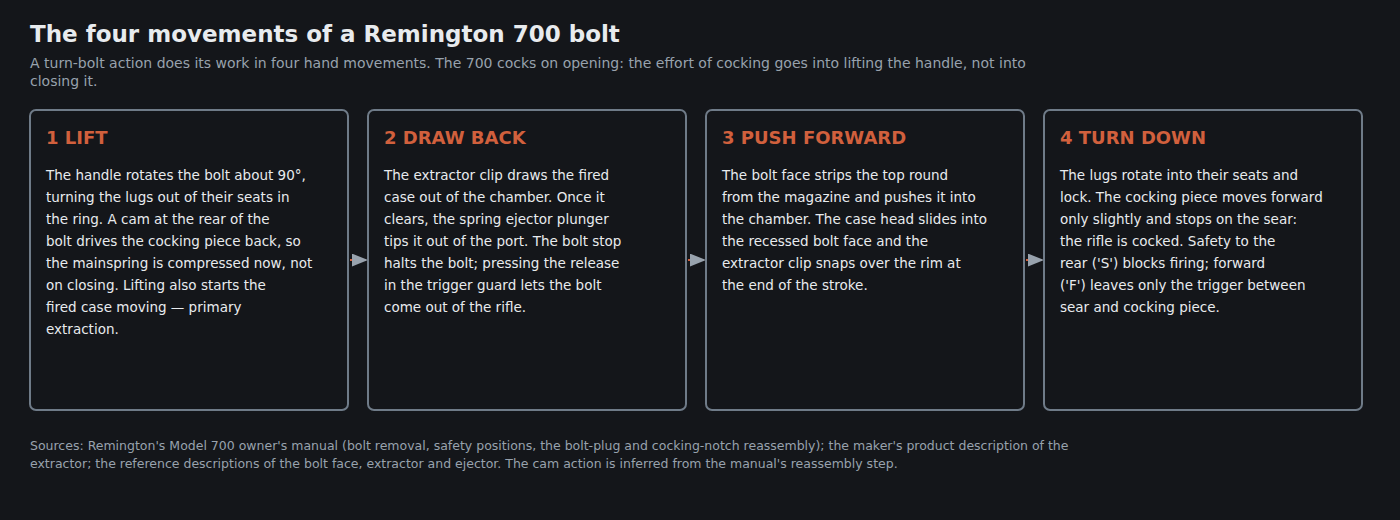
1 — Lift. Rotating the handle upward, about 90°, turns the lugs out of their abutments. As the bolt turns, the cam at its rear drives the cocking piece back against the mainspring. The 700 cocks on opening: the effort goes into lifting the handle, and closing the bolt is comparatively light. The same rotation starts the fired case moving rearward — primary extraction — which is where a stuck case is felt first.
2 — Draw back. The extractor clip draws the case out of the chamber. When the case mouth clears, the ejector plunger tips it out through the port. The bolt stop halts the bolt at the rear of its travel; on the 700, the bolt stop release sits “in the trigger guard” just ahead of the trigger, and pressing it lets the bolt come out of the rifle.8 The Corps’s sniping manual describes the same control on the M40A1: “The bolt stop release is located inside the trigger guard just forward of the trigger. When depressed, it allows the bolt to be removed from the rifle.”9
3 — Push forward. The bolt face strips the top round from the magazine and pushes it into the chamber. The case head slides into the recess, and the extractor snaps over the rim.
4 — Turn down. The lugs rotate into their abutments and lock. The cocking piece is held back by the sear, so the mainspring stays compressed: the rifle is cocked.
Firing. With the safety forward, pulling the trigger lets the sear move out of the cocking piece’s path; the mainspring drives the firing pin forward into the primer.
4.4.1 The safety
Remington’s manual: “To engage the safety mechanism, pull the safety mechanism fully to the rear” — the “S” position — and push it forward to “F” to fire.8 The M40A1’s safety is described identically in the Corps’s manual: “located at the right rear of the receiver, behind the bolt handle. When pulled to the rear, the weapon is on safe.”9 The manual adds a warning that bears on everything in Volume 6: “If your firearm’s internal mechanisms are broken or have been altered, your firearm may discharge even when the safety is on.”8
Exactly which part the safety blocks, and whether the bolt can be opened with the safety on, has differed between trigger generations and is not described in Remington’s current manual. It is not specified here. The functional checks in Volume 5 — the ones the manual itself requires — are what establish that a given rifle’s safety works.
4.5 The Trigger — Three Generations
The trigger is the part of the 700 with a history, and an M40 builder has to know which generation a given action carries, because the answer decides what the owner may adjust, whether a recall applies, and what can be fitted instead. Volume 6 gives the litigation and recall record from the court and the maker. In outline:
The Walker trigger — 1948 onward. The fire control Walker designed for the 721 and carried into the 700 used a separate part called the connector, interposed between the trigger and the sear; how it is alleged to misbehave is the subject of the litigation, not something this volume can settle. The federal court that approved the 2017 class settlement describes the class as rifles “that contain trigger mechanisms utilizing a trigger connector, including the patented Walker Fire Control”, and the plaintiffs’ complaint as alleging that rifles “manufactured by Defendants since 1948 would fire unexpectedly without a trigger pull”.10 Remington denied that the rifles were defective; the court records that “Remington maintains the firearms are not defective, and Remington’s experts have been unable to duplicate an accidental firing without a trigger pull on a rifle in proper working conditions.”10 Every M40 built before the late 2000s carried a Walker-type trigger, tuned by Marine armorers — “modified and lightened”, in the Corps’s fact file.11
The X-Mark Pro — from 2006. Remington’s replacement was connector-less. The settlement’s remedy for Walker-trigger rifles was a “retrofit with a connector-less trigger mechanism”, and the plaintiffs’ own expert “opined the X-Mark Pro trigger mechanism is a safe alternative to the Walker trigger mechanism”.10 It was externally adjustable for pull weight; Remington’s 2016 listing for the SPS Varmint describes an “X-Mark Pro® externally adjustable trigger”.12 It was then itself recalled, in April 2014, for a manufacturing problem — “excess bonding agent used in the assembly process” — affecting rifles made from 1 May 2006 to 9 April 2014.13
The current trigger. The RemArms manual of 2021, revised 2026, describes a trigger preset at the factory to “3 pounds or more”, adjustable by the owner for pull force only, with the supplied wrench or “A standard 1/16” hex key”, lighter counter-clockwise and heavier clockwise, “approximately 1 lb for each full turn of the adjustment screw”, and warns that “The minimum achievable trigger pull force is preset at the factory and must not be altered.”8 The current SPS Varmint product page does not name the trigger.5
Aftermarket triggers for the 700 are made in large numbers precisely because the housing and its two mounting pins are a de facto standard. That is a clone builder’s option and a repair option; it is also, in the court’s words, something whose safety the settlement parties declined to vouch for — “An aftermarket trigger may not be appropriate or safe for a Remington firearm”.10
4.6 The Magazine and the Bottom Metal
The manual distinguishes three kinds of Model 700: “(1) with a FLOOR PLATE, (2) without a FLOOR PLATE and (3) with a DETACHABLE MAGAZINE BOX.”8 The “without” type is the blind magazine of the economy rifles; the floorplate type is the one the SPS Varmint has (“hinged floorplate magazine”);125 the detachable type is a factory option on some models and the basis of the aftermarket detachable-magazine bottom metal.
The bottom metal — trigger guard, floorplate or magazine well, and the action screws that pass through it into the receiver — is also what clamps the barrelled action into the stock. That is why the M40A1 replaced Remington’s aluminium guard with Winchester Model 70 steel, and why the Corps specified a torque for its screws and forbade the sniper to remove them (Volume 2). Every bottom-metal change on a 700 is also a bedding change.
4.7 The Key-Lock (“Security System”)
Some 700s carry a key-operated lock in the bolt shroud. The manual’s warning is brief: “The security system must be disengaged to close the bolt. The Red dot will show.”8 It is not part of any M40 pattern. Whether a given clone’s donor has it is a matter of its date and model.
4.8 What This Means for the M40
Read against the M40’s history, each feature of the 700 has a consequence:
- The turned, round receiver made the 700 easy to true and rebarrel, which is why Quantico could rebuild rifles for five decades — and why a clone builder with a lathe can do the same (Volume 7).
- The separate recoil lug is a weak point the A1 rebuild closed by welding it.
- Bedding matters more on this action than on one with an integral lug, because the lug plate and the round receiver must be held consistently by the stock (Volume 6, Volume 7).
- The clip extractor is the part most likely to fail in the field (Volume 6).
- The trigger has a court and recall record that any owner of a donor rifle needs to check (Volume 6).
- Headspace on a rebarrelled 700 is set at the barrel shoulder against the receiver face, with the recoil lug in between. That subject belongs to the Headspace dive, which covers the whole chain from lug abutments to chamber shoulder in its bolt-face volume and is not repeated here.
4.9 What Could Not Be Verified
- A Remington dimensioned drawing of the 700 action. The diagrams are schematic.
- The “three rings of steel” description as a Remington claim.
- The lock-time figures, which are from the reference literature, not from Remington.
- Which part the safety blocks, and the bolt-lock behaviour of each trigger generation.
- The exact start date of X-Mark Pro production. The recall’s date range begins on 1 May 2006; that is the earliest date attested here.
4.10 Bibliography
Footnotes
-
Scott R. Gourley, “Marine Corps Seeks M40A5 Sniper Rifle Support”, Defense Media Network, 21 July 2009. https://www.defensemedianetwork.com/stories/marine-corps-seeks-m40a5-sniper-rifle-support/ ↩
-
RemArms, “Model 700” firearm history page, consulted 2026-09-19 — introduced 1962; designer Mike Walker. https://www.remarms.com/firearm-history/model-700-history ↩
-
“The Remington Model 700 Story”, American Rifleman — the 721 of 1947 from Walker’s work on the Model 30; the 700 of 1962 with “much tighter internal tolerances”. https://www.americanrifleman.org/content/the-remington-model-700-story/ (consulted 2026-09-19). ↩
-
“Remington Model 700”, English Wikipedia, wikitext consulted 2026-09-19 — the turned receiver from bar stock and stamped small parts of the 721/722; two opposed lugs, recessed bolt face, C-clip extractor, coil-spring plunger ejector and three-piece brazed bolt (cited there to de Haas, pp. 249–251); .695 in bolt body; short action to 2.750 in, long action to 3.340 in; lock times 2.6 ms and 3.0–3.2 ms (cited to van Zwoll, p. 58); Walker’s goal of fast lock time. ↩ ↩2 ↩3 ↩4 ↩5 ↩6 ↩7 ↩8
-
RemArms, product page “Model 700 SPS Varmint”, consulted 2026-09-19 — “Receiver machined from solid-steel bar stock”; “Cylindrical receiver design provides a solid bedding base”; “Integral extractor is set in a groove inside the rim of the bolt face, uniformly supporting the cartridge head”; hinged floorplate; drilled and tapped. https://www.remarms.com/rifles/bolt-action/model-700/model-700-sps-varmint ↩ ↩2 ↩3 ↩4 ↩5 ↩6
-
Brian C. Sheetz and Doug Wicklund, “Long-Range Warriors: The USMC M40 Rifles”, American Rifleman, February 2001 — the welded recoil lug. https://www.americanrifleman.org/content/long-range-warriors-the-usmc-m40-rifles/ ↩
-
McMillan, press release, 5 November 2010, on the M40A1 Commemorative rifle — “surface ground recoil lug; trued receiver face, threads, receiver lug shoulders and bolt head, and finally lapped bolt lugs”. Archived at https://web.archive.org/web/2015id_/http://mcmillanusa.com/documents/Final%20McMillan%20M40A1%20Release.pdf ↩ ↩2
-
RemArms, LLC, Model 700, Seven & 673 Bolt Action Centerfire Rifles owner’s manual, document dated 2021, revised May 2026 (“REV 0526”) — the three magazine types; the safety positions and the warning about altered mechanisms; bolt removal via the bolt stop release in the trigger guard; the security system; trigger pull adjustment (factory 3 lb or more, 1/16 in hex key, about 1 lb per turn, minimum preset); bolt disassembly and reassembly including the cocking notch. https://www.remarms.com/sites/default/files/2026%20Revised%20OMs/700%20Manual%20RD7055%20Final%20F3509%20(REV%200526).pdf (retrieved 2026-09-19 through the RemArms owner’s manuals page). ↩ ↩2 ↩3 ↩4 ↩5 ↩6 ↩7 ↩8
-
Headquarters, U.S. Marine Corps, FMFM 1-3B, Sniping, 28 January 1981, reissued as MCWP 3-15.3 (2004) — §201, the M40A1’s safety and bolt stop release. Internet Archive item
mcwp-3-15.3-sniping-2004. ↩ ↩2 -
Pollard v. Remington Arms Co., 320 F.R.D. 198 (W.D. Mo. 2017), Case No. 4:13-CV-00086-ODS, order of Senior Judge Ortrie D. Smith granting final settlement approval, 14 March 2017. https://www.courtlistener.com/opinion/8793105/pollard-v-remington-arms-co/ (consulted 2026-09-19). ↩ ↩2 ↩3 ↩4
-
Headquarters, U.S. Marine Corps, Fact File, “M40A1 Sniper Rifle”, last modified 15 December 1995 — “modified and lightened trigger”. Archived at https://web.archive.org/web/20070225004953/http://www.hqmc.usmc.mil/factfile.nsf/7e931335d515626a8525628100676e0c/03ae5c82962bc0f48525627b006d3126?OpenDocument ↩
-
Remington Arms, product page “Model 700 SPS Varmint”, archived 20 January 2016 — “X-Mark Pro® externally adjustable trigger” and “hinged floorplate magazine”. https://web.archive.org/web/20160120193845/http://www.remington.com:80/rifles/bolt-action/model-700/model-700-sps-varmint ↩ ↩2
-
Remington Arms Company, LLC, “Product Safety Warning and Recall Notice” (X-Mark Pro), xmprecall.remington.com, as archived — https://web.archive.org/web/2014id_/http://xmprecall.remington.com/ (consulted 2026-09-19). ↩
Comments (0)