Puckle Gun · Volume 4
How It Works: Charger, Screw, Lock, Crane and Tripod
The Puckle gun part by part from the 1718 print and the surviving guns, the firing cycle, the gas seal, the priming problem, and what nine shots a minute really required
4.1 What evidence there is
No manual, drill or maker’s instruction for the Puckle gun is known. The evidence for how it worked is:
- The 1718 print and its key (Volume 1), which is the whole of the patent specification. It names the parts but describes no operation.12
- The 1859 Patent Office abridgment, a one-paragraph description written from the enrolled specification.3
- Photographs of surviving guns: the brass Boughton gun and its square-bored chamber set (Wilcock 2012), the iron gun at Buckler’s Hard (Peel 2014), the Beijing gun (Palace Museum).456
- Two published museum descriptions: St Petersburg (Yefimov 2019, from the 1961 catalogue) and Beijing (Wang Zilin).76
- Modern examinations, chiefly Ian McCollum’s 2016 Forgotten Weapons video, of which only the published summary was read for this dive.8
Where this volume describes how a part worked, it says which of these supports it. Where the sequence of operation is reconstructed from the parts, it is labelled as reconstruction.
4.2 The layout in one picture
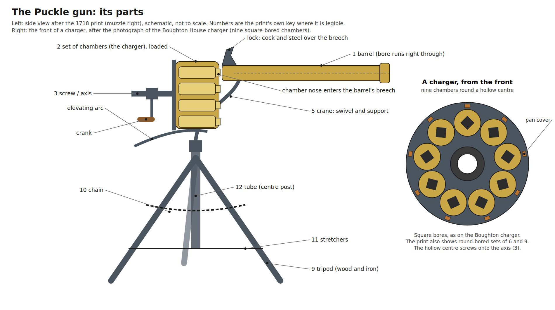
4.3 The parts, by the print’s own numbers
Table 1 — The parts, by the print's own numbers
| No. | Key (legible words; uncertain words marked ?) | What it is |
|---|---|---|
| 1 | The Barrell of the Defence | Smoothbore barrel; the bore runs right through, there is no breech plug |
| 2 | The Sett of Chambers charg’d put on ready for firing | The chamber set, called a “charger” in the Boughton inventory of 1801 |
| 3 | The Screw upon which every Sett of Chambers play(?) … | The axis the chamber set turns on and screws along |
| 4 | A Sett of Chambers ready charg’d to be screw’d on when the first Sett are pulled off to be recharg’d | A spare loaded set; drawn with a crank on its centre and a cover on each chamber |
| 5 | The Crane(?) … turns the Gun round | The swivelling support between tripod and gun |
| 6 | The Cock … | Part of the lock |
| 7 | The Screw … | Not legible enough to identify |
| 8 | The Screw … when the Gun with the Tripod is to be folded up | Fastening used when folding for carriage |
| 9 | The Tripod whereon it plays | Folding tripod, “Wood & Iron” in the declaration |
| 10 | The Chain to prevent the Tripods extending too far(?) | Chain between the legs |
| 11 | The Screw to fix the Tripod … when the same is folded up in order to be carried with the Gun upon a Mans Shoulder | Shown on the stretchers between the legs |
| 12 | The Tube wherein the Pin(?) of the Crane turns | Centre post of the tripod |
| 13 | A Charge of [number illegible] Square Bullets | A multi-cube charge |
| 14 | A single Bullet | Round ball |
| 15 | The front of the Chambers of a Gun for a Boat | Nine-chamber set |
| 16 | The plate of the Chambers of the Gun for a Ship shooting Square Bullets against Turks | Seven square chambers |
| 17 | For Round Bullets against Christians | Six round chambers |
| 18 | A Single Square Chamber | One chamber, stepped nose |
| 19 | A Single Round Chamber | One chamber, stepped nose |
| 20 | a single … (illegible) | Small cube |
| 21 | The Mould for Casting Single Bullets | Bullet mould |
The key is read from the only copy found online, a 1,000-pixel image of the Patent Office sheet.2 A better copy would let items 3, 5 to 8, 10 to 13 and 20 be read in full; they are given here as far as they can be, and nothing in them is load-bearing for the description below.
4.4 The charger
The Patent Office’s 1859 description is the clearest written account: “a rotating chamber-piece, consisting of short cylinders fastened round a hollow centre, which works on a horizontal pin attached to the barrel. Several sets of chamber-pieces, each containing six or more chambers, may be used with the same barrel, so that as soon as all the charges of one set have been fired from one chamber-piece, it is unscrewed from the fixed pin or axis on which it revolves, and another chamber-piece, ready charged, is put in its place.”3
The Boughton chamber set matches that description exactly: nine short brass tubes fastened round a hollow iron centre, on an iron back plate.4 It differs from the modern idea of a revolver cylinder in two ways:
- It is built up, not bored from one block. Each chamber is a separate tube. That made square chambers practical (a square hole is far easier to make in a short tube than at depth in a solid cylinder) and let brass chambers sit on an iron frame.
- It is a magazine as well as a cylinder. The set comes off the gun loaded and goes back on loaded. Wilcock calls it a “drum magazine”; the Boughton inventory calls it a “charger”.
The hollow centre of the Boughton set carries a ring of teeth or notches at its front.4 Their purpose is not stated anywhere read for this dive. They could locate the set angularly on the axis so that a chamber stops in line with the bore, or engage a detent. This is the most important unanswered question about the mechanism, and it is listed below.
4.5 The screw and the crank
Item 3 is “the Screw” on which the chamber sets turn, and the abridgment says a spent set “is unscrewed from the fixed pin or axis”.3 All three photographed guns have a handle or crank projecting behind the chamber set, and the print’s spare set (item 4) is drawn with a crank on its centre.1
So the chamber set travels along a screw thread, not just round an axle. Turning the crank one way runs the set forward toward the barrel; turning it the other way runs it back. Unscrewed completely, it comes off. The Beijing museum description, written without reference to Puckle, says the turntable “is turned by a hand crank”.6
The St Petersburg record adds that “turning the handle brought the chambers one after another to the breech”.7 Whether one crank turned the set about its axis and also drove it along the screw, or the set was turned by hand and the crank only clamped it, cannot be settled from a catalogue sentence. The cycle described below follows the reading most consistent with the parts: a screw that clamps, and a set turned by hand between clamps.
4.6 The gas seal: a chamber nose in the breech
Any revolver leaks gas at the gap between chamber and barrel. Puckle’s answer is visible on the print: the single chambers (items 18 and 19) are drawn with a stepped nose, a short, narrower spigot at the front.1 Screwed forward, the chamber in line pushes its nose into the open breech end of the barrel and the joint closes.
Modern descriptions say the same thing in more detail: after each shot the crank is loosened, the set turned to the next chamber, and the crank “screwed tight again, locking the tapered end of the chamber into the barrel to form a gas-tight seal”. That sentence is from Wikipedia and is unsourced there, but it is exactly what the stepped chamber nose and the screw axis imply together.
The same principle reappears a century later in Elisha Collier’s flintlock revolver, which, in Chinn’s words, had “gas-tight joints between cylinder and barrel, formed by camming forward the cylinder counter-bored at the forward end to mate with the breech end of the barrel”.9 Collier cammed the cylinder forward with a spring and cam; Puckle screwed it forward by hand.
One consequence: the Beijing museum gives the barrel bore as 4 cm and the chamber bore as 2.5 cm.6 If the 4 cm figure was taken at the breech, it may be the counterbore that receives the chamber nose, not the bore. That would reconcile the two numbers, but the article does not say so.
4.7 Ignition: one lock, a pan for every chamber
The print and every photograph show one lock, mounted on the gun above the breech. Puckle’s declaration lists only materials; the key’s item 6 begins “The Cock”.1
Each chamber, however, has its own vent and its own priming: the St Petersburg record says each chamber “has a vent with a cover”; the print’s spare set shows a small cover on each chamber; and the Boughton set has small hinged covers at the rim of its back plate.714
That arrangement has a mechanical consequence that the sources do not spell out. A standard French flintlock combines the steel and the pan cover in one piece, the frizzen, which the falling flint knocks open (see the History of Muzzleloaders, Volume 6). On the Puckle the pans travel with the chamber set while the lock stays on the gun. So the steel cannot also be the pan cover; each chamber’s cover has to be opened separately before that chamber fires, whether by hand or by some part of the gun. Wikipedia states that “rotating the cylinder causes a slot-and-stud mechanism to close the firing pan on the previous chamber and open the next ready to be primed”. That may come from McCollum’s handling of a gun on video; it is not confirmed by any document read here, and it is given as reported.
Separate, covered pans have one real advantage, and it bears on the one trial report. Each chamber’s priming can be put in at loading time and kept covered until its turn. In rain, only the pan in use is ever open.
4.8 Loading a charger
The chambers are open at the front: the photograph of the Boughton set looks straight into nine square bores.4 The vent is at the rear. Each chamber is loaded from its front like a short muzzleloader: powder, then the projectile.
No period loading instruction exists. A correct loading procedure has to deal with what any front-loaded revolving chamber has to deal with:
- Powder charge to a fixed measure, the same in every chamber.
- Projectile seated on the powder with no air gap, by a rammer short enough to reach the bottom of a short chamber.
- Retention: a loose ball in a chamber that points forward and down at times as the set is handled or turned can slide forward. A wad, or a ball sized to grip the chamber wall, holds it.
- Sealing the mouth against flash from the chamber being fired (chain fire; Volume 6).
- Priming each pan and closing its cover.
The 1722 trial report, as cited, says “one man” fired the gun. Loading was almost certainly done beforehand and by others; nine chambers cannot be measured, rammed and primed in the 47 seconds that nine shots a minute allows.
4.9 The firing cycle
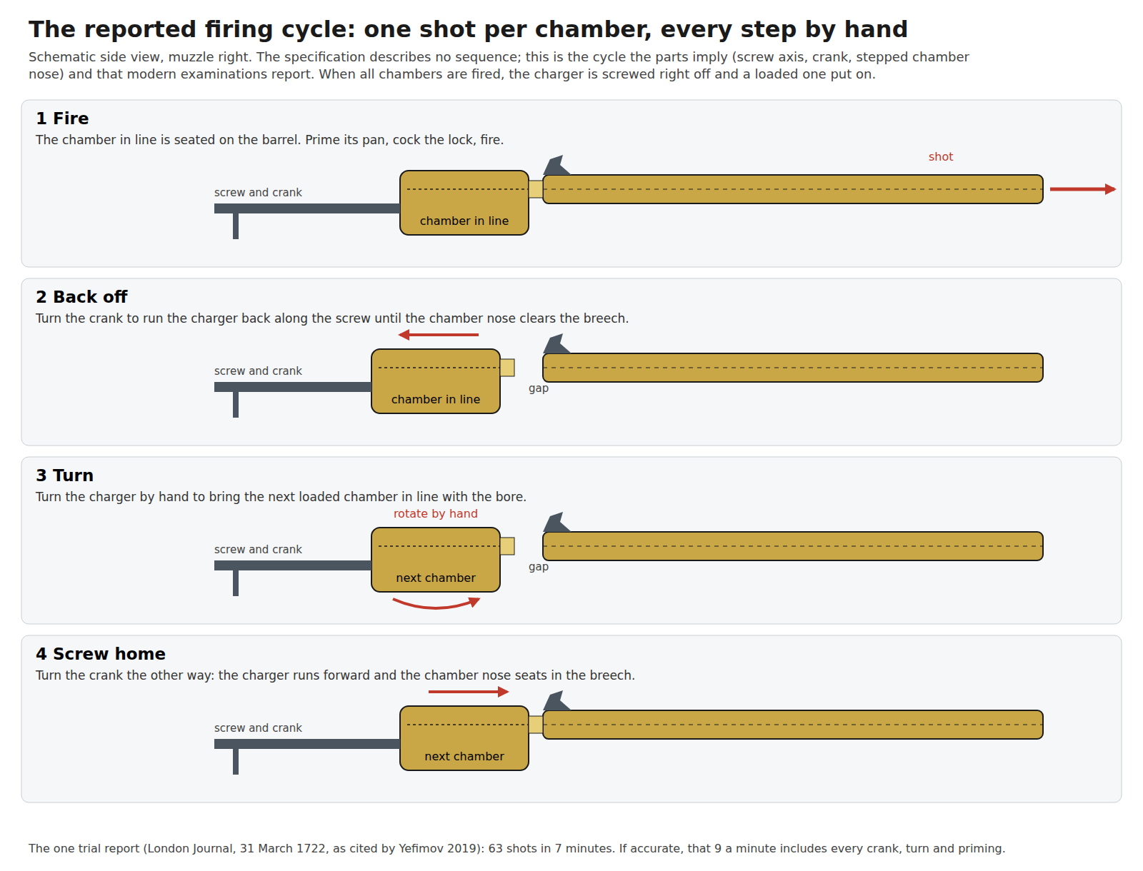
Reconstructed from the parts:
- Fire. The chamber in line is screwed home, its nose seated in the barrel’s breech. Its pan cover is open and primed. The gunner cocks the lock, aims with the crane and elevating arc, and fires.
- Back off. A turn of the crank runs the set back along the screw until the chamber nose clears the breech.
- Turn. The set is turned to bring the next loaded chamber in line. Something must stop it in the right place; on the Boughton set the toothed centre is the most likely part.
- Screw home. The crank runs the set forward and the nose seats. The next pan is opened (by hand or by the reported stud), primed if not already primed, and the cycle repeats.
- Change sets. After the last chamber, the set is unscrewed right off the axis and a loaded one screwed on.
Every step is manual. There is no spring, no cam driven by the trigger, nothing that uses the energy of the shot. That is why the Puckle gun is not a machine gun in any modern technical or legal sense (Volumes 5 and 8).
4.10 The crane, the elevating arc and the tripod
The mount is the part of the design that later writers most admire. Chinn quotes an unnamed nineteenth-century authority on multi-shot arms: “the arm is mounted upon a tripod which very closely resembles the tripods employed with guns of today, that a too great spreading of the legs is prevented by a chain, that stiff rods are used for holding the legs in position, and that for holding the guns at any degree of elevation a device is employed almost identical with that used on some recent forms of machine guns.”9
- The crane (5) is a curved iron arm rising from the centre post (12) and carrying the gun. It swivels in the tube for traverse: “the piece can be swivelled in any desired direction”, in Hodgkin’s 1889 description of the broadside.10
- The elevating arc is a curved bar below and behind the breech. The St Petersburg record describes it as “an arc-shaped iron elevating stand with teeth”.7 Teeth suggest the gun was set at an elevation and held there by a catch.
- The tripod (9) has three legs, a chain (10) between them at mid-height, and rod stretchers (11) lower down. The print’s key says it folds, with the gun, to be “carried … upon a Mans Shoulder”. The Beijing legs are 105 cm and “extensible”.6
The mount lets one man aim the gun freely in two planes while the tripod carries the weight. On a ship’s rail or a gate, that is the point of the design: the Bowles card (Volume 2) shows a man firing it standing at the crank.
4.11 Projectiles: ball, cubes and “granado shells”
The print shows a round ball (14), a single cube (20), a multi-cube charge (13) and a mould for casting single bullets (21).2 It also promises that the machine “can be made to Discharge Granado Shells as well as Bullets”. No surviving set designed for shells is recorded, and no account of the gun firing one was found. Granado shells were small explosive shells with a fuze; the 1,000 “Granado Shells fix’d with Fuzees” in Uring’s 1722 stores list were listed separately, next to four coehorn mortars (Volume 2).
A cube fired through a round bore touches the bore only at its edges. It cannot seal, it will not fly point-on, and its accuracy beyond a short distance would be poor. Against boarders at a ship’s side, a few yards away, that hardly mattered. Whether square shot did more harm than round, as modern summaries assume was the intent, is not discussed in any period source read for this dive.
4.12 Nine a minute: what the number implies
The one performance figure is 63 shots in seven minutes, in rain (Volume 2).7 Taken at face value:
Table 2 — The one performance figure is 63 shots in seven minutes, in rain (Volume 2).[^yefimov] Taken at face value
| Item | Time |
|---|---|
| Average interval between shots | 6.7 seconds |
| Shots per chamber set (nine-chamber set) | 9 |
| Sets fired | 7 (63 = 7 × 9) |
| Set changes inside the seven minutes | 6 |
Each 6.7-second interval had to cover backing off the screw, turning the set, screwing it home, opening and perhaps priming a pan, cocking, aiming and firing. That is quick but not implausible for a practised man with pre-primed chambers. It would not be possible if the sets had to be loaded during the trial. The figure measures a demonstration with pre-loaded sets, which is how the gun was meant to be used: the broadside sells it on being “so quickly loaden”, meaning a fresh set screwed on, not chambers reloaded.
The hub’s History of Muzzleloaders, Volume 7 credits a trained soldier with a flintlock musket with “perhaps two or three aimed shots a minute”. The Puckle’s advantage was real, three to four times that, but it came from pre-loading, not from mechanism.
4.13 Design judgements
What worked, as far as the evidence goes:
- Interchangeable pre-loaded chamber sets. The gun’s whole sustained rate depends on them. It is the same idea as the swivel gun’s removable breech chambers before it and the spare loaded cylinders carried for percussion revolvers after it.
- The screw-driven gas seal. A positive, adjustable clamp of chamber to barrel, a century before Collier.
- The mount. Tripod, chain, stretchers, crane and toothed elevating arc are, as Chinn’s source said, close to what machine guns used in the nineteenth century.
What did not, or cannot be shown to:
- Ignition. Flint ignition with an exposed pan per chamber and a separate lock is the gun’s weak point. A misfire costs a full cycle to clear, and an open pan next to a firing chamber is a chain-fire risk (Volume 6).
- Complexity and cost. Nine separate chambers, a threaded axis, a crane and a tripod in brass and iron, for a smoothbore that fired one ball at a time.
- Weight. The St Petersburg gun weighs 52.9 kg.7 “Portable” meant two men, or one with a folded tripod on his shoulder for a short way.
4.14 What could not be verified
- How the chamber set was stopped in line with the bore: the toothed centre of the Boughton set is the likeliest part, but its function is not described in any source read.
- Whether pans opened automatically (the reported slot and stud) or by hand.
- The lock’s design: no photograph read shows it clearly enough to say whether it is a frizzen-type lock with a separate steel, a snaphance-type lock, or something else.
- How the crank and screw were used step by step: the cycle above is a reconstruction.
- Loading drill: none known.
References
Footnotes
-
James Puckle, specification of Patent No. 418 (print and declaration of 25 July 1718), as reproduced in George M. Chinn, The Machine Gun, vol. I (Bureau of Ordnance, 1951), p. 18. https://archive.org/details/TheMachineGunVolume1ByGeorgeMChinn, accessed 19 October 2026. ↩ ↩2 ↩3 ↩4 ↩5
-
Patent Office, “A.D. 1718. May 15. No 418. Puckle’s Specification (3rd Edition)”, one sheet, via Recreation vol. 4 (1896); Wikimedia Commons, https://commons.wikimedia.org/wiki/File:Puckle_gun_advertisement.jpg, accessed 19 October 2026. Key read from the 1,000-pixel image. ↩ ↩2 ↩3
-
Patents for Inventions. Abridgments of Specifications relating to Fire-arms and other Weapons, Ammunition, and Accoutrements (Great Seal Patent Office, 1859), p. 26. https://archive.org/details/patentsforinven04offigoog, accessed 19 October 2026. ↩ ↩2 ↩3
-
Paul Wilcock, “The Armoury of His Grace the Duke of Buccleuch and Queensberry”, Arms & Armour 9, no. 2 (2012); author’s version, http://eprints.hud.ac.uk/17394/1/BUCCLEUCH_PROJECT_Royal_Armouries_version_2_5_FinalProofEDIT.pdf, p. 6, accessed 19 October 2026. ↩ ↩2 ↩3 ↩4 ↩5
-
Mike Peel, photographs of the Buckler’s Hard gun, 14 September 2014, Wikimedia Commons, CC BY-SA 4.0, https://commons.wikimedia.org/wiki/File:Buckler%27s_Hard_Maritime_Museum_06_-_Puckle_Gun.jpg, accessed 19 October 2026. ↩
-
Wang Zilin, 《从前膛炮、子母炮到轮子炮》, Palace Museum, Beijing, https://img.dpm.org.cn/Uploads/pdf/2237/T00016_00.pdf, accessed 19 October 2026. ↩ ↩2 ↩3 ↩4 ↩5
-
S. V. Yefimov, Voenno-istoricheskii zhurnal, 2019, no. 2 (in Russian), https://cyberleninka.ru/article/n/skorostrelnye-artilleriyskie-orudiya-pervoy-poloviny-xviii-veka-v-sobranii-voenno-istoricheskogo-muzeya-artillerii-inzhenernyh, accessed 19 October 2026. ↩ ↩2 ↩3 ↩4 ↩5 ↩6
-
Ian McCollum, “Puckle Gun (Video)”, Forgotten Weapons, 25 December 2016, https://www.forgottenweapons.com/puckle-gun-video/, accessed 19 October 2026 (published summary only). ↩
-
George M. Chinn, The Machine Gun, vol. I (Bureau of Ordnance, 1951), pp. 17–20 (the quoted nineteenth-century authority on the Puckle mount, p. 19; Collier, p. 20). https://archive.org/details/TheMachineGunVolume1ByGeorgeMChinn, accessed 19 October 2026. ↩ ↩2
-
J. Eliot Hodgkin, “Anticipations of Modern Inventions: Puckle’s ‘Defence’”, Notes and Queries, 7th ser., vol. 8 (9 November 1889), p. 365. https://archive.org/details/sim_notes-and-queries_1889-11-09_8_202, accessed 19 October 2026. ↩


Comments (0)