Moving Ejection Port · Volume 6
The Port Cassette for the Printed MP7
A drop-in module behind the ejection port: where it goes in the shell, a dimensioned drawing, the parts list with dated prices, print settings, assembly, starting firmware values, the Analog Discovery Pro bench test with its pass criteria, and the same rails reused for concept A
6.1 A module, not a feature of the shell
The first build is a 3D-printed MP7 (decision D35), and the MP7 Printed Build dive designs its shell. This volume gives that shell one thing to accommodate behind its ejection port: a port cassette, a self-contained printed frame carrying the port solenoid, two rods, the moving shuttle, its spring and its stops, held by two screws at each end.
A module rather than parts printed into the shell, for three reasons from the volumes before: everything that wears is in it, so it can be replaced without touching the shell (Volume 5); it can be built and run on the bench before the shell exists, which is the order the build is going in; and both of decision D5’s concepts can be compared in the same shell, by fitting the cassette (concept B) or leaving it out and running the kick mass behind the port (concept A1, 6.9).
6.2 Where it goes
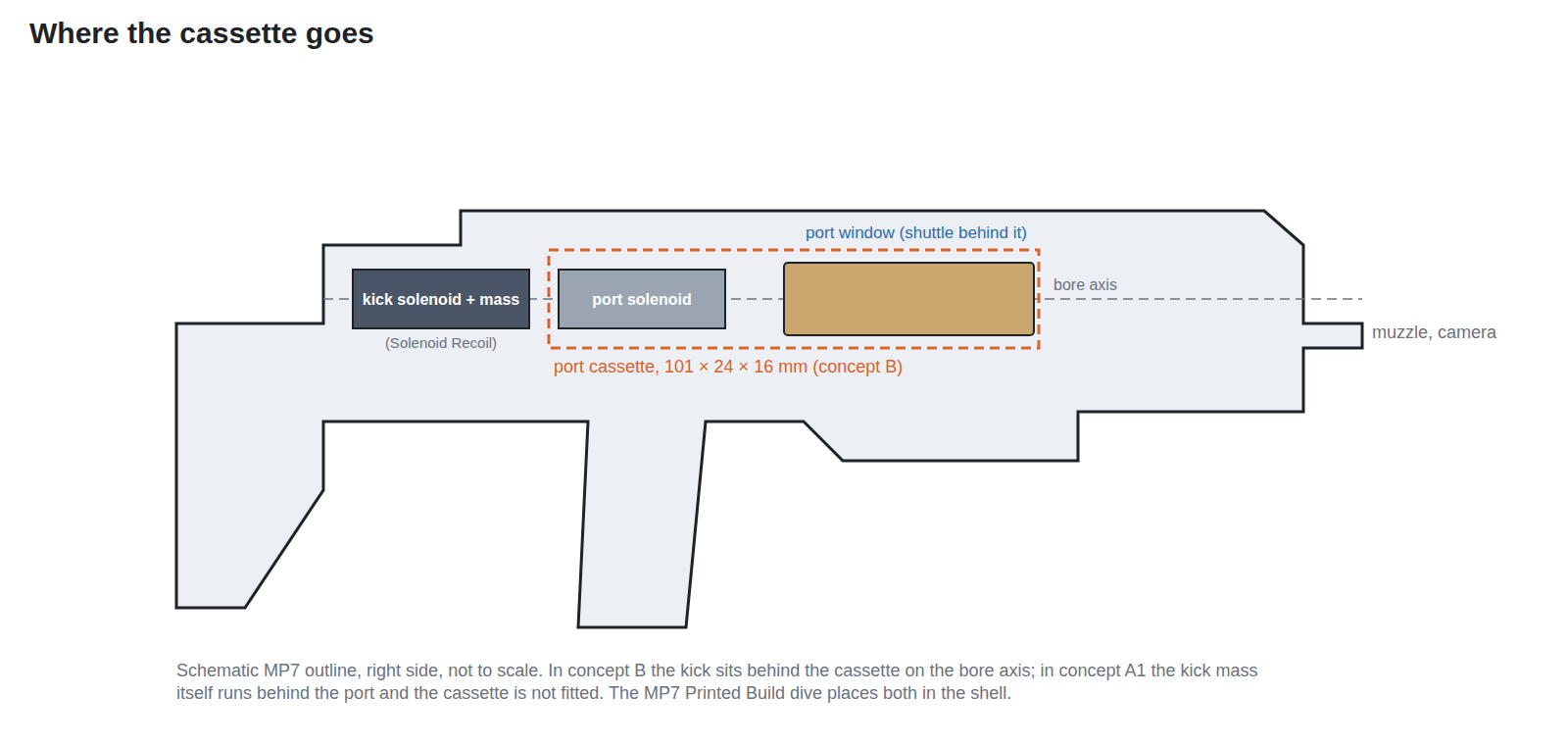
What the shell has to provide, for the MP7 Printed Build dive:
Table 1 — What the shell has to provide, for the [MP7 Printed Build](/light-guns/actual-builds/mp7-printed-build/) dive
| Feature | Value (provisional) | Note |
|---|---|---|
| Port window in the right wall | 40 × 12 mm, from the starter model | Its real size and position are taken from the shell’s STEP; the cassette is drawn around whatever they are |
| Bay behind the window | 101 × 24 × 16 mm clear | Along the bore axis, inboard of the right wall |
| Mounting | Four M3 screws into the cassette’s heat-set inserts, through bosses in the shell | Or screws from inside the receiver into bosses on the shell, whichever the shell’s split allows |
| Clearance to the wall | 0.5 mm between the shuttle’s outer face and the wall’s inner face | The shuttle is seen through the window at that depth |
| Cable | A two-wire lead from the port solenoid to the carrier board’s second solenoid connector | JST VH, per Reference Electronics Vol 5 |
| Behind the cassette | The kick solenoid and mass on the bore axis | Placed by the Solenoid Recoil dive’s rules |
The window’s size is the one dimension this dive does not set. H&K publishes no port dimensions (Volume 1), and the printed build’s starter model is the source: its Volume 2 chose a STEP assembly that its seller describes as 1:1. The HK MP7 dive notes that the licensed Umarex gas-blowback replicas copy the real gun’s dimensions “1:1” by Deutsches Waffen-Journal’s account, so a replica measured with calipers is the check. Two sanity bounds come from the cartridge: a port that passes a 30.5 mm case is longer than that, and the window should be a little longer still.
6.3 The drawing
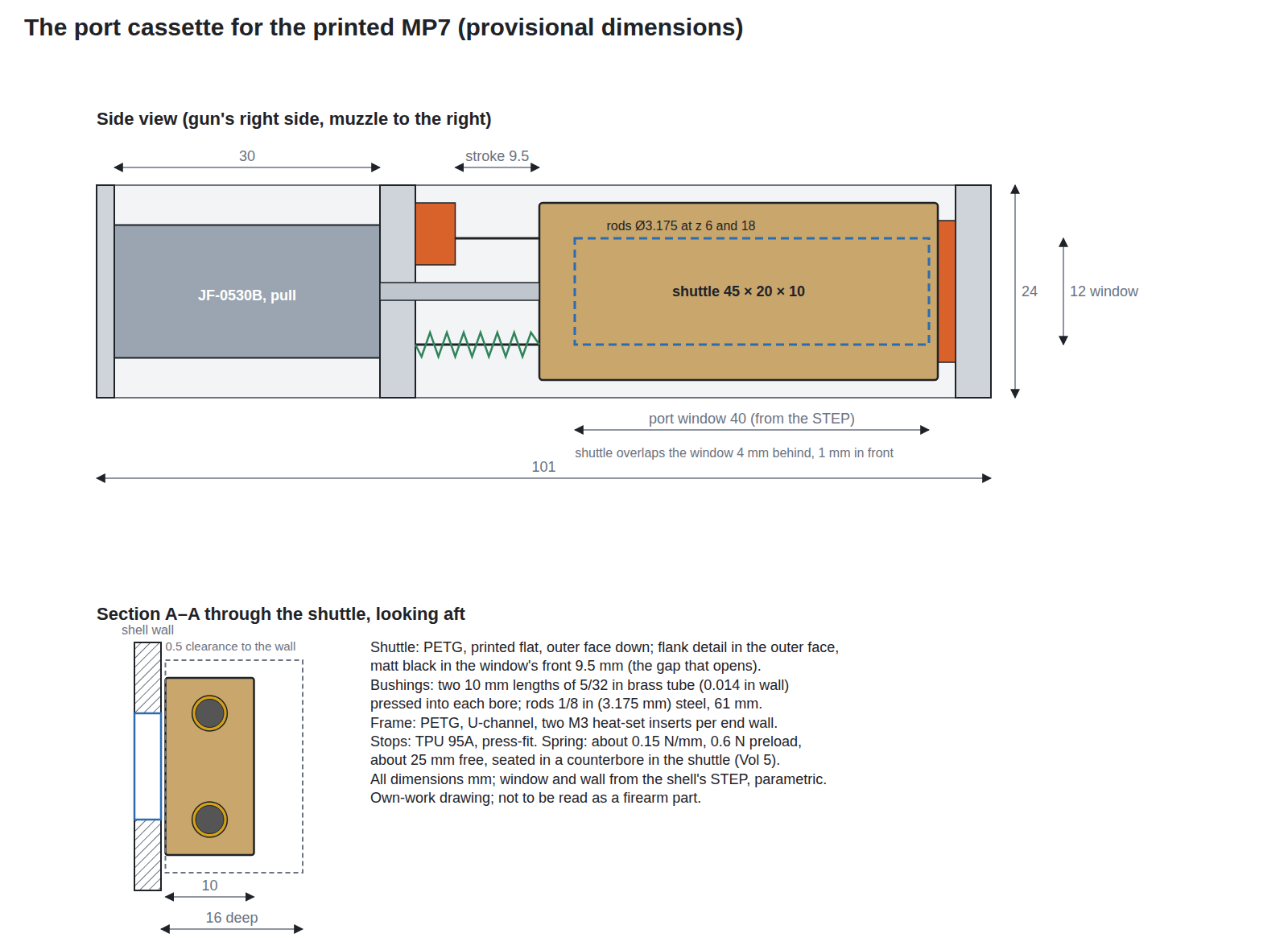
Table 2 — The drawing
| Item | Dimension | Why |
|---|---|---|
| Frame | 101 × 24 × 16 mm, PETG U-channel | Holds every part; four M3 inserts in its end walls |
| Solenoid | JF-0530B class, 13 × 15 × 30 mm body, 10 mm stroke | Volume 4’s pick |
| Rods | Two, 1/8 in (3.175 mm) steel, 61 mm long, at 6 and 18 mm height, 12 mm apart | Two rods stop the shuttle rotating; spacing as wide as the shuttle allows |
| Shuttle | 45 × 20 × 10 mm PETG, about 6–8 g with pockets on the inboard face | Window 40 + 4 behind + 1 in front; the 20 mm height hides the rods behind the window’s edges |
| Stroke | 9.5 mm | The solenoid’s 10 mm less the 0.5 mm residual gap (Volume 5) |
| Gap that opens | 9.5 mm at the window’s front edge, painted matt black behind | What reads as “the bolt moved” |
| Bushings | Two 10 mm lengths of 5/32 in × 0.014 in brass tube per bore | 0.128 in bore over a 0.125 in rod (nominal) |
| Front stop | TPU 95A pad, 2 mm | Takes the spring return |
| Rear stop | TPU 95A sleeve on the upper rod, 4.5 mm | Stops the shuttle 0.5 mm before the plunger bottoms |
| Spring | About 0.15 N/mm, 0.6 N preload, about 25 mm free, in a counterbore in the shuttle’s rear face | Volume 5 |
| Plunger link | 2 mm steel pin through a printed clevis on the shuttle, the hole slotted 0.5 mm vertically | Takes up misalignment between plunger and rods without binding |
All of it is parametric in Fusion, with the window’s length and height and the stroke as user parameters, so the drawing follows the shell’s STEP and the bench’s choice of stroke.
6.4 Parts list
Prices as read on the named page on 19 October 2026, single quantity, before shipping, except where marked.
Table 3 — Parts list
| # | Part | Qty | Price | Source | Why this, and why not the others |
|---|---|---|---|---|---|
| 1 | JF-0530B 12 V open-frame solenoid | 1 | From the D15 order; not readable on 18 Oct | Marketplace | Volume 4 |
| 2 | Shuttle, PETG | 1 | About $0.25 of filament (about 8 g at $29.99/kg) | Prusament PETG, Prusa store (as recorded by MP7 Printed Build) | Volume 5 |
| 3 | Frame, PETG | 1 | About $0.40 (about 13 g) | as above | |
| 4 | Stops, TPU 95A | 2 | Under $0.10; a 25 g sample is $3.59 | Prusa store1 | Volume 5 |
| 5 | 1/8 in steel rod, 61 mm | 2 | Not read on a maker’s page | Drill rod or dowel stock, cut on the lathe | Volume 5 |
| 6 | 5/32 in × 0.014 in brass tube, 10 mm | 4 | Not read on a maker’s page (K&S stock item) | Hobby or hardware shop | Volume 5 |
| 7 | Return spring, about 0.15 N/mm, about 25 mm free | 1 (buy several) | To be chosen from Lee or Century stock tables | leespring.com; mwcomponents.com | Volume 5; the two stock springs read are each wrong for it |
| 8 | 2 mm steel pin, about 12 mm | 1 | Not priced | Dowel pin stock | |
| 9 | M3 × 5.7 heat-set insert | 4 | $10.90 per 100 | CNC Kitchen US store, as recorded by MP7 Printed Build | Its table’s 4.0 mm hole and 1.6 mm wall fit the end walls |
| 10 | M3 screws | 4 | Workshop stock | — | |
| 11 | Two-wire lead with JST VH plug | 1 | Not priced | Matches the board’s connector | Reference Electronics Vol 5 |
| 12 | Slotted optical switch and flag, bench only | 1 | Not priced | — | Arrival-time sensor for 6.8 |
The printed and metal parts of one cassette cost a few dollars; the solenoid is the only part whose price matters, and it is already being bought.
6.5 Printing
Starting values, for the lab’s Prusa MK3S+ printers:
- PETG, Prusa’s recommended 230 °C first layer and 240 °C after, bed 85 °C then 90 °C, and not on the smooth PEI sheet, where Prusa warns that adhesion “may be too strong”.2
- Shuttle printed flat, outer face down, so the face that shows in the window is the smooth bed side, the layer lines run along the travel, and the bores and lug lie in the tougher orientation (Volume 5). Four perimeters round each bore.
- Bores printed 0.1 mm under the brass tube’s 3.97 mm outside diameter and the tube pressed in, or printed close and reamed. A printed hole’s size varies with printer and filament, so a test coupon with a range of bore sizes is printed first.
- TPU 95A for the stops, slowly, as flexible filaments need.
- Finish. The shuttle’s outer face carries the flank detail from the shell’s model, and the cavity behind the window’s front 9.5 mm is painted matt black.
6.6 Assembly
- Fit the four heat-set inserts into the frame’s end walls.
- Press the brass bushings into the shuttle’s bores; check the shuttle slides on both rods by hand, through its whole length, with no tight spot.
- Fit the TPU rear sleeve on the upper rod and the front pad in the front wall.
- Mount the solenoid to the frame by its tabs, with an air gap to the printed wall (Volume 5).
- Put the spring in the shuttle’s counterbore over the lower rod; slide the rods through the rod block, the shuttle and into the front wall.
- Pin the plunger to the shuttle’s clevis.
- Push the shuttle back by hand: it should stop on the TPU sleeve with the plunger just short of its seat (a 0.5 mm feeler gauge between plunger and pole is the check), and return briskly to the front pad when released.
- Fit the lead, and screw the cassette into the shell or a bench base.
6.7 Starting values for the fork
These are first settings for the Our Firmware dive’s fork, to be replaced by the bench’s numbers:
Table 4 — These are first settings for the [Our Firmware](/light-guns/building-the-electronics/our-firmware/) dive's fork, to be replaced by the bench's numbers
| Setting | Start at | Then |
|---|---|---|
| Port enabled | on | |
| Delay after SOL_CMD falls | 5 ms | Measured decay time (Reference Electronics §5.13), plus margin |
| Port pulse | 15 ms | Measured arrival time plus 2 ms |
| Set current (VREF divider) | 1.0 A (VREF 1.18 V) | Lowest current that arrives inside the pulse at 18 V |
| Hold duty (PWM on EJECT_CMD, ≥ 20 kHz) | 30 % | Lowest duty that holds against the spring with the gun shaken |
| Hold limit | 10 s | Shorter if the port coil’s sensor rises |
| Magazine size (own-count mode) | 40, off by default |
6.8 The bench test
The rig is the lab’s Digilent Analog Discovery Pro ADP3450: four analogue input channels (14-bit, at least 55 MHz, up to 125 MS/s) and 16 digital I/O, as Digilent’s specification was read for the Solenoid Recoil and MP7 Donor Build dives. The regulated stage has no power shunt; its IPROPI pin is the current signal while driving, and OUT2, about 0.8 V above the rail while the coil coasts, shows the decay (Reference Electronics §5.12). OUT2 exceeds the ADP3450’s ±25 V input and is probed ×10.
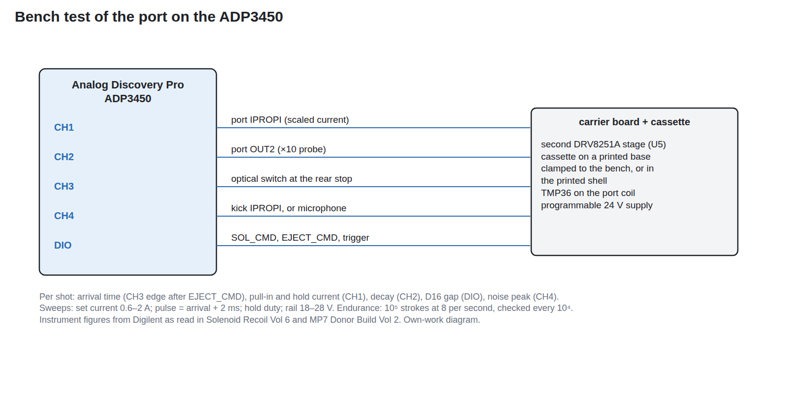
Steps.
- Static. Weigh the shuttle and the solenoid’s plunger (lab scale). Measure the spring’s force at home and fully back with a force gauge or a luggage scale. Check the residual gap with a feeler gauge.
- Arrival. At 24 V, fire single port strokes at set currents from 0.6 to 2 A in steps, ten each, with a 50 ms pulse. Read the arrival time on channel 3 and the current on channel 1. Plot arrival time against current.
- Trimmed pulse. Set the pulse to arrival plus 2 ms and repeat. Read the return time (channel 3’s falling edge to the front pad, or a second switch).
- Rail. Repeat step 3 at 18, 20, 24 and 28 V with the supply’s current limit set; the regulated stage should make arrival nearly independent of the rail.
- D16. Fire kick and port together from the fork, a hundred shots. On the digital channels, confirm EJECT_CMD never rises while SOL_CMD is high, and measure the gap. Then force an overlap in a test build of the firmware and confirm the hardware interlock holds the port stage off.
- Hold. Run the last-round sequence: pull-in, hold at the starting duty, release after 10 s. Read the hold current (channel 1, drive intervals only) and the port coil’s temperature every second. Lower the duty until the shuttle drops, then set it 50 % above that.
- Noise. With a microphone on channel 4 at a fixed distance, record one shot with the TPU pads fitted and one with them replaced by hard printed stops. Compare peaks.
- Endurance. 10⁵ strokes at eight a second, about three and a half hours, stopping every 10⁴ to record arrival time, return time, the spring’s force and any visible wear at the points of Volume 5’s wear map. Then 30 minutes in the shell in a warm room, and check the frame for softening near the solenoid.
Pass criteria, from Volume 2:
Table 5 — Pass criteria, from Volume 2
| Requirement | Pass |
|---|---|
| P-1 time | Out and back within 63 ms of the trigger with the kick first, at 18 V and 28 V |
| P-2 D16 | No overlap in 100 shots; the interlock holds under a forced overlap |
| P-5 hold | Holds for 10 s against a shake; coil sensor rise under the fork’s limit |
| P-6 noise | The port’s peak below the kick’s on the same microphone trace |
| P-7 life | 10⁵ strokes with arrival time changed by less than 20 % and no cracked part |
6.9 Concept A1 on the same rails
Concept A1 (Volume 3) makes the kick mass the part seen in the port. The cassette’s geometry carries over with three changes: the port solenoid is replaced by the kick solenoid chosen on the Solenoid Recoil bench, which is larger, so the frame grows rearward; the shuttle becomes a printed skin over a steel slug sized for the kick; and the rear stop becomes hard, because the rear landing is now the kick. The front pad, the rods and the bushings stay. Building both on the same rails is what lets decision D5 be decided on feel, with the shell and everything else unchanged.
6.10 Files, kits and licences
The cassette is this project’s own design: a frame, rods, a block and a spring, sized around a window. It contains nothing of the real weapon’s mechanism, and nothing modelled on H&K’s bolt (Volume 1). The window’s size and position come from the printed shell’s starter model, whose licence and provenance the MP7 Printed Build dive deals with. Under decisions D8 and D12 the STEP, F3D and print files stay in the private repository until there is a working model and the owner decides what to publish.
6.11 Why this, and why not the others
Table 6 — Why this, and why not the others
| Choice | Picked | Why, and why not |
|---|---|---|
| Module or printed into the shell | Module | Replaceable; testable before the shell; lets A and B swap. Printed into the shell: fewer parts, but every wear point becomes a reprint of the receiver |
| Guide | Two steel rods | One rod lets the shuttle rotate; printed rails wear (Volume 5) |
| Solenoid position | Behind the shuttle, pulling | In front, pushing: puts the coil in the fore-end beside the camera cable (Volume 4) |
| Stroke | 9.5 mm | Full 10 mm: the plunger would bottom; longer: a lever (Volume 3) |
| Window size | From the shell’s STEP | From photographs: not measurable (Volume 1) |
6.12 What could not be verified, and questions
Not verified. The real window size. Every time, current and force in this volume, which are starting values. The spring part number. The prices of rod, tube, pin and lead.
Questions for the owner, also listed in the dive’s working notes:
- Does the printed shell’s split allow the cassette to be screwed in from inside the receiver, or does it need bosses through the right wall?
- Is a licensed replica available to measure the port window (the D4 donors, if bought)?
- Is a measurement microphone available for the ADP3450, or should one be bought for the noise checks?
- Should the board’s second spin bring IN2 of the port stage to a pin, to allow a latching solenoid (Volume 4)?
- Is the hold-open wanted in own-count mode, or only when a game supplies the ammunition count?
Sources
The PETG price and the heat-set insert table are from the MP7 Printed Build dive’s research notes (Prusa store and CNC Kitchen US store, read 2026-10-19). The stage, interlock and current signal are from Reference Electronics Vol 5; the ADP3450’s figures from the Solenoid Recoil and MP7 Donor Build dives, citing Digilent. The replica statement is from HK MP7 Vol 4, citing Deutsches Waffen-Journal, 2015.
Footnotes
-
Prusa Research, Prusament TPU 95A, https://www.prusa3d.com/category/prusament-tpu/, read 2026-10-19. ↩
-
Prusa Knowledge Base, “PETG”, https://help.prusa3d.com/article/petg_2059, read 2026-10-19. ↩
Comments (0)