Moving Ejection Port · Volume 5
Springs, Stops, Noise and Wear
Sizing the return spring against the solenoid's pull and the time budget; soft stops at both ends and a residual gap at the coil; where the noise comes from; rods and bushings; PETG, nylon and TPU from their makers' data; why no printed part should flex on every shot; and a life target that can be tested
5.1 A part stopped twice per shot
Every shot starts the port part from rest, stops it at the back, starts it again and stops it at the front. At OpenFIRE’s default eight shots a second that is sixteen stops a second, and the design life proposed in Volume 2 (P-7) is a million strokes. The arcade cabinets met the same problem with a cushion rubber on the plunger, a stopper rubber on the slide, bushes on shafts, and a manual that expected the solenoid to wear out (Arcade Light Guns Vol 5). This volume makes the same choices with numbers, for the concept B cassette of Volume 6 and the concept A carrier of Volume 3.
5.2 The return spring
The return spring has four jobs, and they pull against each other:
- Return in time. Volume 2’s budget leaves roughly 20 to 25 ms for the return.
- Never beat the solenoid. Its force at every point of the stroke must stay below the solenoid’s pull at the set current, or the part stalls partway.
- Arrive gently. Whatever energy it gives the part is spent at the front stop as a tap and a noise.
- Live. Stay inside its maker’s deflection limit and never go solid.
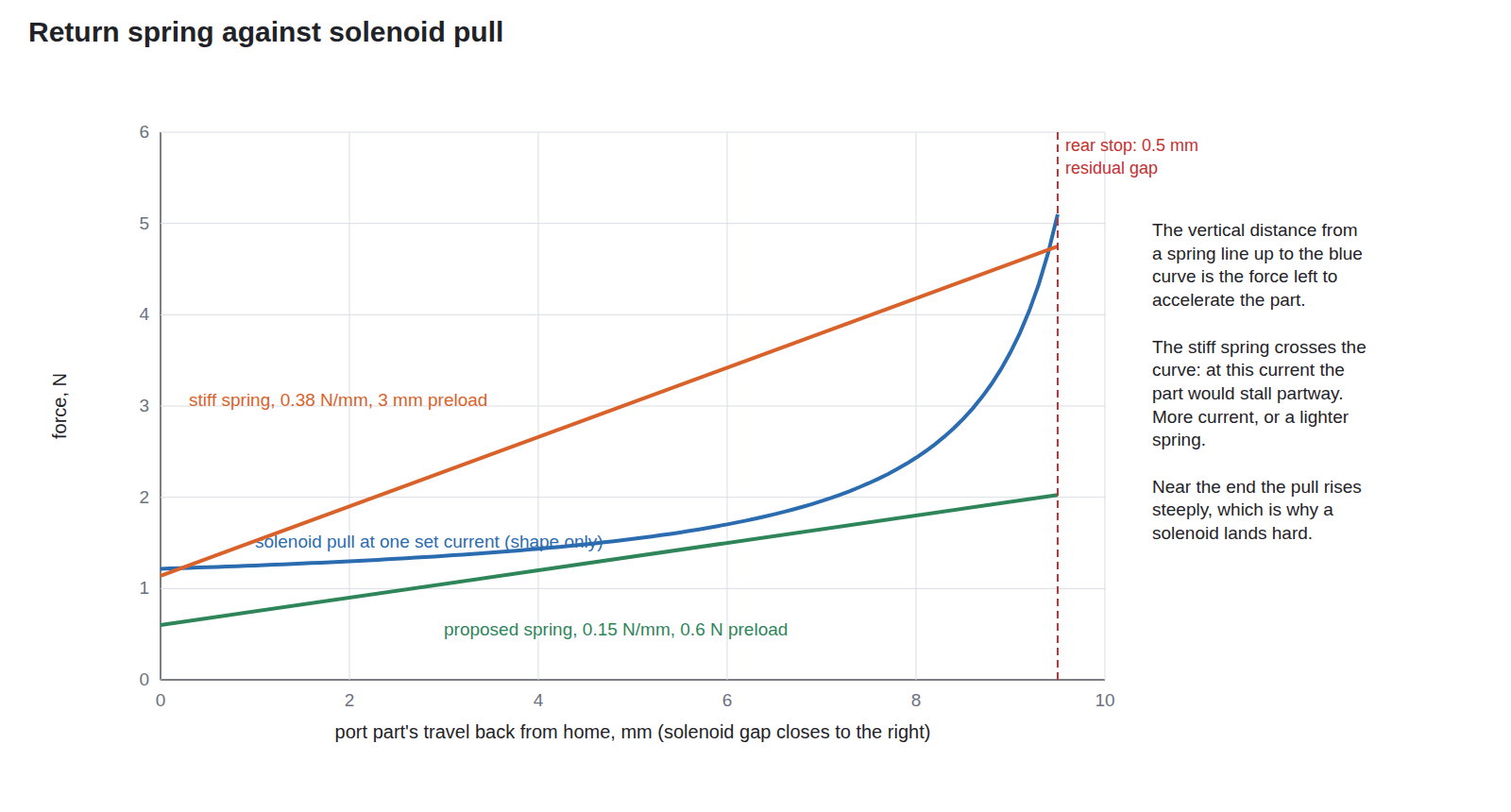
What the time budget asks for. Integrating a linear spring’s force over a 9.5 mm return (this dive’s port_dynamics.py):
Table 1 — What the time budget asks for. Integrating a linear spring's force over a 9.5 mm return (this dive's portdynamics.py)
| Spring | Moving mass | Return time | Speed at the front stop | Energy into the stop |
|---|---|---|---|---|
| 0.1 N/mm, 0.1 N preload | 16 g | 55 ms | 0.35 m/s | 1.0 mJ |
| 0.1 N/mm, 0.4 N preload | 16 g | 28 ms | 0.69 m/s | 3.8 mJ |
| 0.15 N/mm, 0.6 N preload | 16 g | 23 ms | 0.84 m/s | 5.7 mJ |
| 0.2 N/mm, 1.0 N preload | 16 g | 17 ms | 1.09 m/s | 9.5 mJ |
| 0.38 N/mm, 1.14 N preload | 16 g | 16 ms | 1.16 m/s | 10.9 mJ |
The middle row is the proposal: inside the budget, with about half the stop energy of the stiffest. Preload matters more than rate. A light spring fitted with almost no preload is gentle and quiet, and takes twice the time.
Two stock springs bracket it, and neither is it. Lee Spring’s LC 026EE 10S, stainless, 9.53 mm outside diameter, 0.66 mm wire, 28.58 mm free length, 0.38 N/mm, 8.72 N at solid, costs $8.04 each in ones and $1.53 at a hundred (19 October 2026).1 It is the stiff line in the chart and would stall a small solenoid at a modest current. Century Spring’s 12404CS, music wire, 7.52 mm outside and 6.81 mm inside diameter, 0.36 mm wire, 14.99 mm free, 0.1 N/mm, 1.2 N “suggested max load” and 12.45 mm “suggested max deflection”, is too short: a 9.5 mm stroke plus the 4 mm of preload the proposal needs is 13.5 mm, past its limit; MW Components’ page shows no price.2 The spring to buy is about 0.15 N/mm, about 25 mm free, with at least 14 mm of usable deflection, an inside diameter over 3.5 mm to clear a 1/8 in rod, and an outside diameter under 9 mm, chosen from Lee’s or Century’s stock tables on the day. The free length is why Volume 6 seats it in a counterbore in the shuttle.
If the solenoid carries its own spring. Many open-frame push-pull solenoids have a return spring on the plunger; Adafruit’s listing for its small one says “captive armature with return spring”.3 Whether the JF-0530B units arrive with one is a check on delivery; its force adds to the cassette’s spring and is measured with it.
In concept A the spring returns the kick mass, tens of grams. For the same return time the force scales with the mass, and so does the energy at the front stop; the stop in 5.3 matters more there.
5.3 The stops
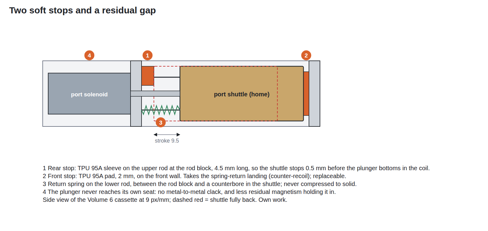
The front stop takes the spring’s energy on every return, 4 to 10 mJ in the table above. A pad of TPU 95A printed on the lab’s printers is the first choice: Prusa describes its TPU as “known mainly for its flexible properties and extreme wear resistance”, and sells Prusament TPU 95A at $34.99 for 500 g, or a 25 g sample for $3.59, which is enough for hundreds of pads (19 October 2026).4 A printed pad can be shaped as a press-in plug and replaced in a minute. The alternatives are a Sorbothane sheet die-cut to shape, which is the better damper but for which no price was found on the maker’s sheet page in a search on 19 October 2026, and a nitrile O-ring on the rod, which is cheap and standard but has a hard, small contact. Both are bench comparisons, not the starting point.
The rear stop in concept B is not the kick and should be soft as well. It does a second job: it stops the shuttle 0.5 mm before the solenoid’s plunger bottoms in its coil. Three things follow. There is no steel-on-steel landing, which is the loudest noise in the mechanism. The force at the end is that of the curve half a millimetre before its steepest point, which is still far above the spring. And a plunger that never closes its magnetic circuit completely is less likely to be held in by residual magnetism after the current stops, a reason solenoid designers fit non-magnetic stop shims; that the JF-0530B needs it is untested. A TPU sleeve on the upper rod, against the rod block, does it. The bench sets its length.
In concept A the rear landing is the kick and stays hard (Volume 3), and only the front stop is soft.
5.4 Noise
A light gun is played in a living room, and the port mechanism adds noise to a gun whose kick already makes plenty. The sources, loudest first by expectation:
- The plunger landing in the coil. Removed by the rear stop’s residual gap in concept B; in concept A it is the kick.
- The front-stop tap. Set by the spring’s arrival energy and softened by the pad.
- Rattle. Clearance in the bushings and the clevis pin, excited by the kick. It grows with wear.
- The chop. The regulated stage chops at an estimated 12 to 19 kHz while holding a current, and Reference Electronics notes the coil “may sing faintly”; a PWM hold at 20 kHz or more adds a second tone at the top of hearing (Reference Electronics Vol 5 §5.12).
The lab catalogue (_shared/lab_capability.md) lists no sound-level meter or measurement microphone. A measurement microphone into a spare ADP3450 channel gives a waveform per shot that can be compared before and after a change, which is all a design needs; absolute decibels are not. Volume 6’s plan puts it on channel 4.
5.5 Rods and bushings
The arcade guided its slides on shafts in bushes, and so does this design: a printed part sliding on printed rails would wear its own guide.
Table 2 — Rods and bushings
| Option | For | Against |
|---|---|---|
| Brass tube pressed into the shuttle, on steel rod | Brass on steel is a classic dry light-duty pair; K&S telescoping tube is sold in hobby shops; a 5/32 in tube with a 0.014 in wall has a 0.128 in bore, 0.003 in (0.08 mm) over a 1/8 in (3.175 mm) rod, by the nominal sizes | Price not read on a maker’s page; clearance is nominal and is checked with the rods on hand |
| Printed bore on steel rod | No extra part | PETG sliding on steel at sixteen strokes a second has no published wear data; the bore is the shuttle, so wear means a new shuttle |
| igus iglidur sleeve bearing, 3 mm bore (GSM-0304-03) | A made plastic bearing, dry-running, 3 mm × 4.5 mm × 3 mm | Prices found only on non-US distributor pages; not read directly |
| Sintered bronze (oil-impregnated) bushing | Self-lubricating, very durable | Bulkier for the same bore; not priced |
| Linear ball bushings | Lowest friction | Far bigger than the space; rattle |
Proposed: brass tube on 1/8 in steel rod, two 10 mm lengths per bore, and a drop of light oil. Steel rod of that size is drill rod or dowel stock, cut and faced on the lab’s lathe. If the rods on hand measure metric, the 3 mm igus sleeve is the like-for-like substitute.
5.6 Printed materials
The lab’s printers are two heavily modified Prusa MK3S+, which Prusa’s product page lists for PLA, PETG, Flex and others, with ABS, ASA and nylon only with its enclosure and filtration add-on (MP7 Printed Build, research notes; _shared/lab_capability.md).
PETG for the shuttle and the frame. Prusa’s technical data sheet for Prusament PETG (version 1.1, 16 February 2022) gives a density of 1.27 g/cm³, a heat deflection temperature of 68 °C, a printed tensile yield strength of 47 to 50 MPa, a tensile modulus of 1.5 to 1.6 GPa, unnotched Charpy “no break”, and notched Charpy 6 ± 1 kJ/m² in one print orientation and 3 ± 1 in the other.5 Prusa’s own guide calls it a material whose “high tenacity and flexibility often prevent it from breaking”, with “great layer adhesion”, for mechanical parts below 80 °C.6 Two consequences:
- Orientation halves the notched toughness. The shuttle is printed flat, outer face down, so the bores, the clevis lug and the stop faces lie in the stronger plane and the layer lines run along the direction of travel.
- 68 °C is close to a solenoid’s working temperature. OpenFIRE’s thermal protection doubles the off-time at 38 °C and stops at 45 °C on the coil’s sensor (Solenoid Recoil Vol 4), but a coil’s inside runs hotter than its case. The solenoid is mounted to the frame through its steel frame’s tabs with an air gap, not pressed into a printed pocket, and the frame is checked for softening after the endurance run.
Nylon would be the better sliding and wearing material: Prusa’s guide calls polyamide “extremely resilient … resistant to abrasion” with a low coefficient of friction, but also hygroscopic, absorbing “up to 10% of filament weight”, needing drying “at least 4 hours”, and adds that “printing in a well-ventilated room or in an enclosure is a must”.7 On unenclosed MK3S+ printers it is a later option for the shuttle if PETG wears, not the first.
TPU 95A for the stops (5.3).
In concept A the carrier is a printed skin over a steel slug (Volume 3); the skin carries no load but its own inertia, and is bonded and pinned to the slug.
5.7 Flexures and fatigue
A printed flexure, a hinge or spring made of the part’s own plastic, is the cheapest mechanism there is, and a tempting way to make a return spring or a latch. For a part that cycles on every shot it is the wrong choice, for a reason of evidence: no fatigue data for unfilled FDM-printed PETG was found in a search for this volume. The studies located were of carbon-fibre-filled PETG, a finite-element simulation, and a continuous-carbon-fibre nylon composite, none of which describes a plain printed flexure. A million cycles of bending in a material with no published endurance curve is a guess.
The design rule that follows: no printed part flexes on every shot. The only cyclic flexure in the cassette is the steel spring, whose maker publishes its limits. Printed snap-fits are used only for assembly, which they see a few times. The stops are compressed, not bent. If a printed flexure is ever wanted, the bench endurance test of Volume 6 is the only evidence that will do.
5.8 Where it wears
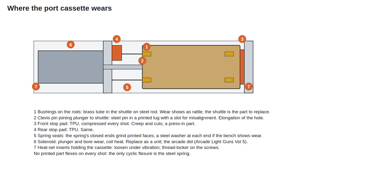
The arcade’s lesson was to design for replacement. The cassette of Volume 6 is a module held by two screws at each end, so any of these points is a cassette out and a part swapped, with the shell untouched. The heat-set inserts follow CNC Kitchen’s table as the MP7 Printed Build dive records it: M3 × 5.7 mm in a 4.0 mm hole with at least 1.6 mm of wall, $10.90 for 100 from CNC Kitchen’s US store (19 October 2026). A thread-locker on the screws keeps them from walking out under the kick.
5.9 Why this, and why not the others
Table 3 — Why this, and why not the others
| Choice | Picked | Rejected, and why |
|---|---|---|
| Return spring | About 0.15 N/mm, 0.6 N preload, about 25 mm free, from a stock table | 0.38 N/mm stock spring (Lee LC 026EE 10S): stalls a small solenoid, doubles the stop energy. 0.1 N/mm, 15 mm free (Century 12404CS): cannot take the preload within its deflection limit; slow without it |
| Front stop | Printed TPU 95A pad, press-in | Sorbothane: better damping, no price found, needs cutting; O-ring: hard small contact |
| Rear stop (concept B) | TPU sleeve leaving 0.5 mm residual gap | Letting the plunger bottom: the loudest noise, and a possible residual-magnetism stick |
| Guide | Brass tube on 1/8 in steel rod | Printed bore: unknown wear, and wear means a new shuttle; igus sleeve: no US price read; ball bushings: too big |
| Shuttle and frame | PETG, printed flat | Nylon: better wearing, but needs drying and an enclosure the printers do not have; PLA: lower heat resistance (not assessed here) |
| Return mechanism | Steel spring | Printed flexure: no fatigue data for plain printed PETG |
5.10 What could not be verified
- No fatigue data for unfilled FDM PETG; the design avoids needing it.
- The brass tube’s and steel rod’s prices were not read on a maker’s page; the 0.08 mm clearance is from nominal sizes.
- Whether the JF-0530B has its own return spring, and whether it sticks at a closed gap.
- The noise figures: none measured; the lab has no sound-level meter.
- Which of Prusa’s two Charpy columns is the flat print; this volume takes the higher figure to be the flat (XY) orientation, as is usual on such sheets, and the bench settles it.
Sources
Arcade practice is cited in Arcade Light Guns Vol 5; the chop frequency in Reference Electronics Vol 5; OpenFIRE’s thermal thresholds in Solenoid Recoil Vol 4; the printers, PETG price and heat-set inserts in the MP7 Printed Build dive’s research notes. Spring arithmetic: this dive’s 04-templates/port_dynamics.py.
Footnotes
-
Lee Spring, “Compression Spring LC026EE10S Stainless Steel”, https://www.leespring.com/product/compression-spring-lc026ee10s-stainless-steel, read 2026-10-19. ↩
-
MW Components (Century Spring), “12404CS – 0.59 Inch Music Wire Compression Spring”, https://mwcomponents.com/shop/12404cs, read 2026-10-19. ↩
-
Adafruit, product 412, https://www.adafruit.com/product/412, read 2026-10-19. ↩
-
Prusa Research, Prusament TPU 95A, https://www.prusa3d.com/category/prusament-tpu/, read 2026-10-19. ↩
-
Prusa Polymers, Prusament PETG technical data sheet, version 1.1, 16 February 2022, as hosted at https://www.3dprintergear.com.au/assets/files/technical-data-sheet%20(1).pdf, read 2026-10-19. ↩
-
Prusa Knowledge Base, “PETG”, https://help.prusa3d.com/article/petg_2059, read 2026-10-19. ↩
-
Prusa Knowledge Base, “Polyamide (Nylon)”, https://help.prusa3d.com/article/polyamide-nylon_167188, read 2026-10-19. ↩
Comments (0)