Modding Classic Light Guns · Volume 2
Repairs at the Bench — Test Methods, Switches, Cables, Sensors, Batteries and Missing Parts
A test ROM that tells a dead Zapper from a dead console port, a GunCon that reports its own faults, the nine-wire cable by colour, why the Zapper's sensor is fixed with a donor board and not a part, replacement GunCon 3 markers from a CC0 schematic, and two adaptors that make a gun work on a console it was not sold for
2.1 The tests come first
Volume 1 ended with a triage: right television, right port, right game, bright enough, calibrated. Once those are settled, the next step is still not the screwdriver. Both of the commonest classic guns can be tested electrically from outside, and the tests say which part to look at before the shell comes apart.
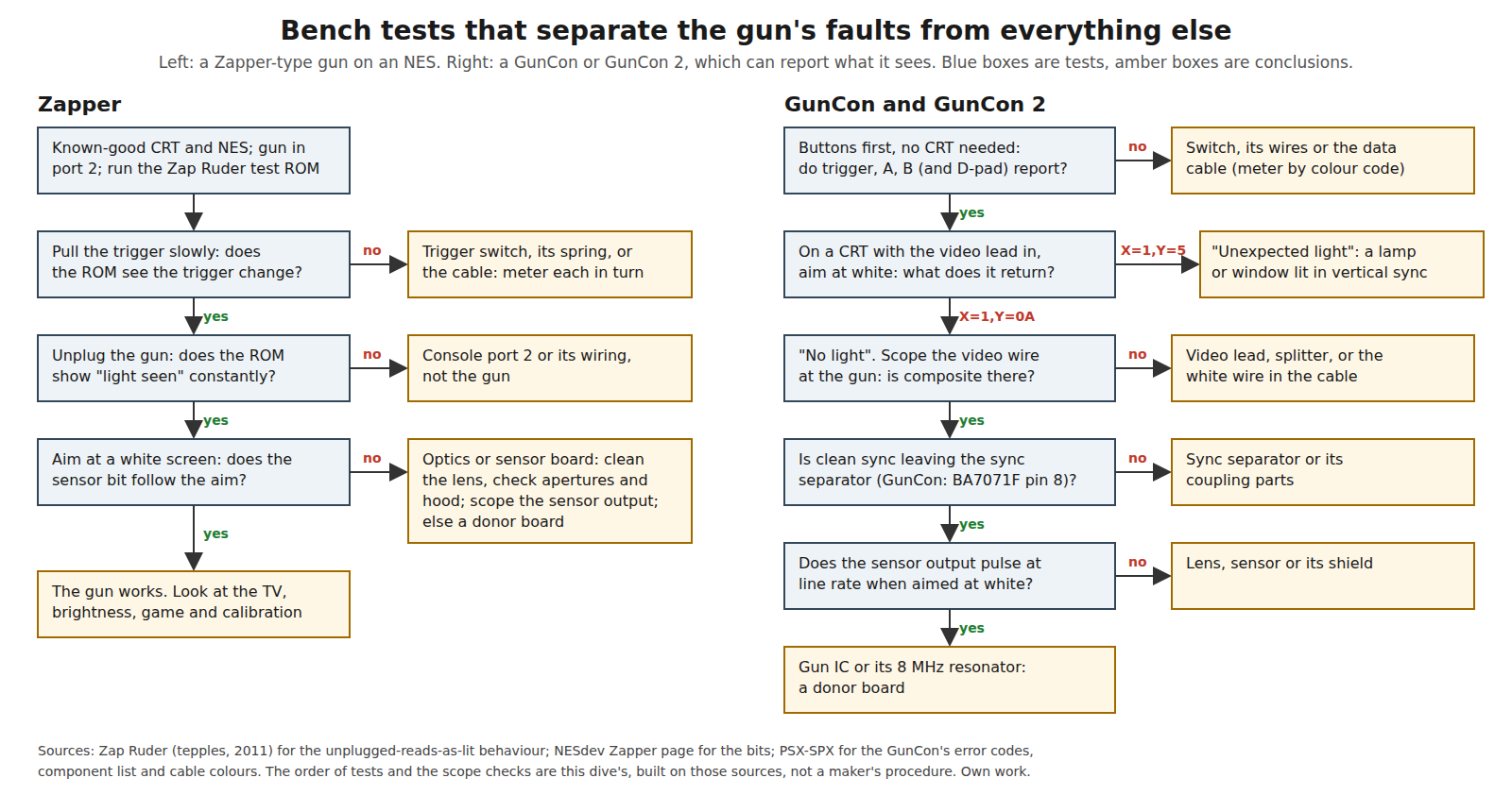
The order in that figure is this dive’s, not a maker’s procedure: no Nintendo or Namco service procedure for the guns was found. Each step rests on a documented behaviour, given below.
2.2 Testing a Zapper with Zap Ruder
Zap Ruder is a Zapper test program for the NES, posted by the NESdev developer tepples in September 2011 (version 0.02 on 30 September 2011, downloadable from his site). Its point, in his words, was to test “the photosensor, not just the trigger”: it includes kernels that find the scanlines on which the sensor turns on and off, a menu driven by pointing the gun, and a small tennis game.1 Run from a flash cartridge on a real NES and a CRT, it is the closest thing to a service tool the Zapper has.
Three results do most of the work:
- The trigger. Pull slowly and watch the trigger state change. NESdev records that the Zapper’s trigger bit reads differently when released or fully pulled than when half-pulled, and that a 10 µF capacitor in the gun stretches the release to about 100 ms against the console’s 10 kΩ pull-up.2 A trigger that never changes state is a switch, spring or cable fault (§2.4).
- The unplugged gun. tepples noted that “an empty controller port and an unplugged Zapper appear as a photosensor that is constantly lit up”, because the light bit reads 0 in both cases.1 So with the gun unplugged, the program should show light seen constantly. If it does not, the console’s port is not delivering the line, which matches an iFixit owner’s report of disconnected pins inside the NES’s second controller connector.3 The gun is not the fault.
- The aimed gun. Point it at a white area and away. The sensor result should follow the aim, scanline by scanline. If the trigger works and the port is good but the sensor never reports light, the fault is in the barrel: lens, apertures, hood or sensor board (§2.6).
2.3 Testing a GunCon by asking it
The GunCon is easier, because it says what it sees. PSX-SPX records that it returns X (8 MHz clocks since horizontal sync) and Y (scanlines since vertical sync) every frame, and reserves two pairs of values for errors: X = 0001h, Y = 0005h for light seen during vertical sync (“unexpected light”, a lamp or sunlight), and X = 0001h, Y = 000Ah for no light at all.4 Any game’s calibration screen shows whether the gun is producing coordinates; a homebrew or emulator-side display that shows the raw values is better, because it distinguishes the two errors.
The GunCon 2 can be tested without a PlayStation 2. It enumerates over USB as 0B9A:016A, and the Linux driver written for it exposes the raw position as absolute X and Y and the trigger as the left button. Its README gives a working calibration range of about 175 to 720 in X and 20 to 240 in Y.5 With the gun on a PC and its composite lead fed from a CRT source, the raw numbers appear in any input-event viewer. The buttons report without any video at all, which tests every switch and the USB cable before a CRT is involved. The MiSTer project’s notes show the same gun working with a composite-sync tap from a modern FPGA system, and warn that calibrating the minimum and maximum of one axis to the same value makes the MiSTer divide by zero and crash.6
Then the scope, working back from the console end:
- The video wire at the gun. On the GunCon, composite arrives on the white wire, J1 pin 9 (§2.5). No composite here means the lead, the Y-splitter (the GunCon 2’s “External Cable”, the first thing lost from a loose gun, per Console Light Guns, Volume 5) or the conductor.
- Sync out of the separator. PSX-SPX identifies U2 as a BA7071F sync separator with its composite input on pin 1 and its sync output on pin 8 to the gun IC.4 Clean composite in and nothing out points at U2 or its coupling parts.
- The sensor. Aimed at a white screen, the sensor’s output should pulse at the line rate, about 15.7 kHz on NTSC (63.5 µs per line). A flat output at a bright screen means the lens, the sensor or its shield.
- Past that, the 44-pin NAMCO103P gate array and its 8 MHz resonator remain. Neither is a part a repairer can buy; a donor board is the repair.
2.4 Triggers and buttons
The Zapper’s trigger is a mechanical switch that grounds the signal line when pulled,7 returned by a spring. The faults are mechanical: a weakened or unhooked spring, a bent or oxidised contact, a trigger moulding cracked at its pivot. The repair is cleaning and re-forming the contact, refitting or replacing the spring. A German forum thread on reducing the Zapper’s trigger pull exists, showing the spring and contact can be adjusted, but it was not readable for this dive.8 Photograph the spring’s seating before lifting the trigger: it is held by the shell halves.
The GunCon’s trigger is a DIP switch on its own small board (DN-P-0501), wired to the main board by two black wires marked T1 and T2; the side buttons A and B are on a second board (DN-P-0502) with red and white pairs.4 Each is testable with a meter across its pair. The GunCon 2’s trigger is a microswitch on the small D-pad board, which reaches the main board through a seven-way ribbon (pin-out in Volume 4); its A, Start and Select buttons are carbon-pill contacts under rubber domes on the main board.9
Choosing a replacement switch. No maker’s part number for any of these switches was found, so a replacement is chosen by measurement, not by catalogue.
Table 1 — 2.4 Triggers and buttons
| Choice | For | Against |
|---|---|---|
| A switch of the same body size, actuator and operating force, measured from the original (chosen) | Fits the moulded pocket; the trigger feels as it did; no shell work | Needs the original measured: body length and width, pin pitch, actuator height and force |
| Any subminiature microswitch that fits | Easy to buy | A different operating force changes the trigger feel; a different actuator height changes pre-travel and can leave the switch held on or never reached |
| A Hall-effect trigger, as chosen for the MP7 build (D8) | No contact to wear | Needs a powered sensor and firmware support; makes sense only when the gun is being converted (Reference Electronics, Volume 4), not when restoring it |
Carbon-pill contacts under rubber domes (GunCon 2) fail by wear of the carbon or contamination of the board pads. Cleaning both with isopropyl alcohol is the usual first step; that is general practice, not a Namco instruction.
2.5 Cables
The cable is the classic gun’s commonest wearing part: it flexes at the grip exit thousands of times and at the plug every time the gun is put away. A meter on continuity, flexing the cable at each end, finds an intermittent conductor.
For the GunCon, PSX-SPX gives the colour of every wire from the gun’s connector J1 (Volume 1, §1.4): green +3.5 V, brown ground, black /ACK, red select, yellow data, orange command, blue clock, grey shield, white composite video.4 That table makes the repair routine: cut back past the break, or replace the cable from a donor controller lead of at least nine conductors with a shield, and match colours or ring each conductor through.
Two cautions:
- Shorten, do not lengthen, the composite run without thought. The video wire carries the sync the gun counts from. Lengthening it is unlikely to matter at composite frequencies, but a broken shield on that conductor invites noise into the sync separator. Keep it shielded.
- Extension leads behave differently by gun. A 2026 test found that controller extension cables work with the GunCon but not with the Konami Justifier,10 which is what the two designs predict: the GunCon sends data, while the Konami gun’s timing pulse travels on the IRQ10 line.
2.6 Lenses, apertures and sensors
Cleaning. Sega’s own instruction for the Light Phaser is to clean the lens only with a soft cloth and never with benzene, alcohol or thinner (Console Light Guns, Volume 7). That is the safe rule for every gun’s lens: the plastics crack or cloud with solvents.
Apertures and hoods set the field of view. In the Zapper they are two moulded orange rings in the barrel and a sheet-metal hood over the photodiode; in the GunCon, a metal shield over the sensor.11 4 Anything that moves them changes what the gun sees, which is why a gun that has been opened and closed carelessly can work worse afterwards. Reassemble with the hood seated and the barrel parts in their moulded locations.
The sensor chain. The Zapper’s filter IC, the Sharp IR3T07A, has no datasheet and no known source; Nick Bild, who identified it, calls it “completely undocumented”.7 Component-level repair stops at the passives around it. The repair is a donor board from a Zapper with a cosmetically ruined shell, which is common and cheap (Console Light Guns, Volume 7 prices a loose Zapper). The GunCon’s sensor is a 3-pin shielded part with no part number recorded;4 the same advice applies.
A scope shows whether the sensor stage is alive before deciding. Aimed at a white screen on a CRT, the Zapper’s sensor output should carry a burst of pulses at the line rate whenever the beam passes the aimed patch. Bild found the photodiode’s anode also shows slow light changes as voltage changes,7 which is the starting point for every attempt to make the gun see an LCD (Volume 5).
2.7 Batteries and the wireless guns
The Super Scope runs on six AA cells and the Menacer on six AAA cells in its pistol section (Console Light Guns, Volume 3); both are the guns most often found with leaked cells in them. Console Light Guns Volume 7 puts opening the battery door first when buying one. The general repair for alkaline leakage, which is potassium carbonate deposits on nickel-plated steel springs, is to remove the residue with a mild acid (white vinegar or lemon juice on a swab), neutralise and dry, then clean the contact back to bright metal; a spring whose plating has gone is replaced rather than polished. That is general practice for battery compartments, not a Nintendo or Sega procedure, and no maker’s procedure was found. Check the board traces next to the compartment as well: leakage wicks along wires.
The receivers are passive in the sense that they have no batteries, but they are separate small boxes that are often lost. A Super Scope or Menacer without its receiver cannot work and has no substitute; buy the pair.
2.8 Missing parts: splitters, sensor bars and GunCon 3 markers
The GunCon 2 splitter. Without the External Cable the gun has no video and will not register. Console Light Guns Volume 5 concludes from Namco’s own wiring diagram that any composite splitter with the right genders does the same job.
The Wii sensor bar. The Wii’s sensor bar contains only two clusters of infrared LEDs; any infrared source of suitable wavelength in the right places stands in for it, which is why battery-powered third-party bars exist. This is the same physics the OpenFIRE emitter bar exploits (Reference Electronics, Volume 6).
GunCon 3 marker units. Without both marker units a GunCon 3 cannot aim (Console Light Guns, Volume 6). A community replacement has been published under CC0: a printable case and a schematic of three 850 nm infrared LEDs in series with a 22 Ω resistor from 5 V.12
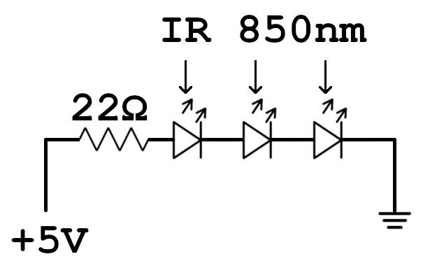
The arithmetic is worth doing before building one. With three LEDs dropping about 1.4 to 1.6 V each at tens of milliamps (typical of 850 nm emitters; the repository names no LED part), the resistor sees 0.2 to 0.8 V, so the current is roughly 10 to 35 mA and depends strongly on which LED is fitted and on the supply’s exact voltage. A constant-current drive, like the one designed for this project’s own emitter bar in Reference Electronics, Volume 6, removes that dependence. Two things are not established: whether Namco’s units emit at 850 nm, and how the originals are powered. The repository gives neither, so the replacement should be tested against the gun before being trusted.
2.9 Making a gun work on another console
Two published modifications make a classic gun work where it was not sold to.
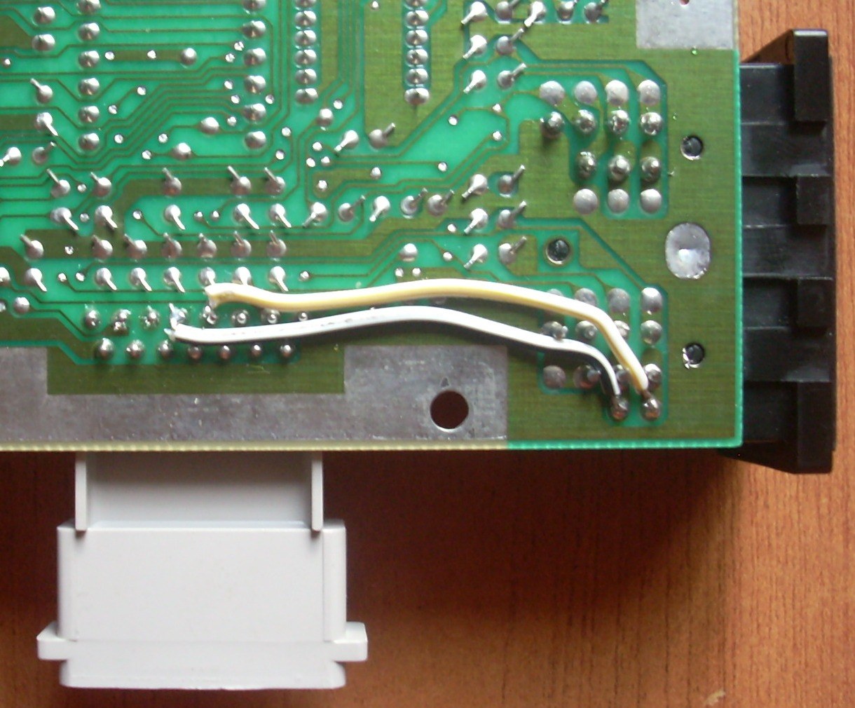
An NES Zapper on an AV Famicom. The AV Famicom has NES-style controller ports, but it expects a light gun on its 15-pin expansion port, as the original Famicom did, so a Zapper in port 2 does nothing. Famicom World’s fix is two wires on the solder side of the main board, from the expansion port’s light-gun pins to the second controller port’s pins.13 NESdev records the same thing from the other side: those two pins are “normally not connected” on the AV Famicom, and “there is a published hardware modification”.2
A Master System Light Phaser in Mega Drive games. Ben Ryves built a pair of adaptors that let the Light Phaser play games written for the Sega Menacer and the Konami Justifier on the Mega Drive.14
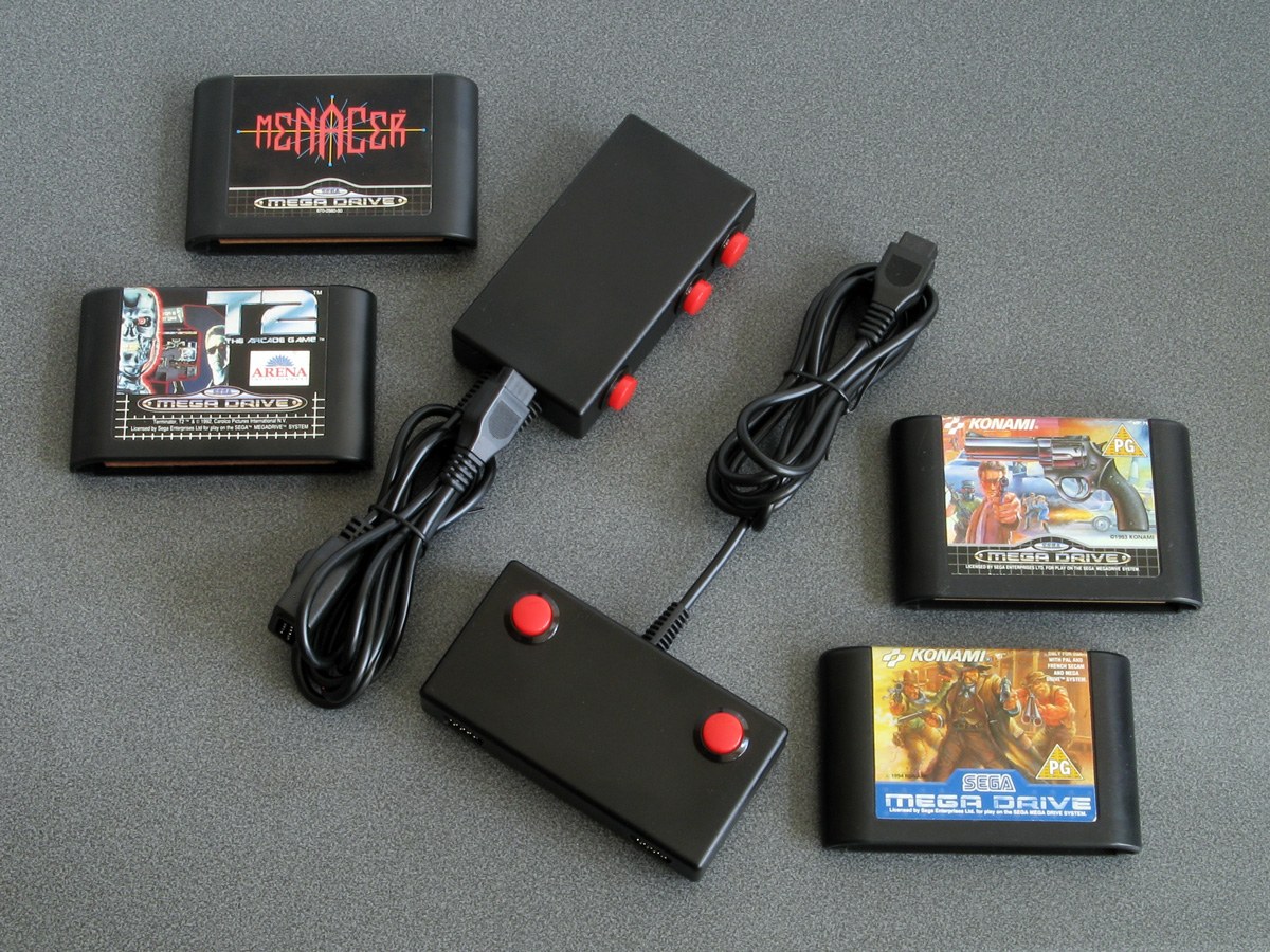
The Menacer adaptor is the instructive one. The Light Phaser’s sensor pulse is latched by two NOR gates, then delayed by an RC network “to imitate the wireless overhead of the real Menacer”, so that the Menacer games’ calibration lands on target. He found CMOS gates unreliable and recommends TTL (SN74ALS02AN, “I can confirm that they work”); the delay is trimmed with a 470 Ω variable resistor against 100 nF, and “a fixed 220Ω resistor had the aim pretty much dead-on”. The Justifier adaptor uses two 74HC157 multiplexers and has known problems with some Mega Drive models and with every American Laser Games title. All of it was tested on CRTs.14
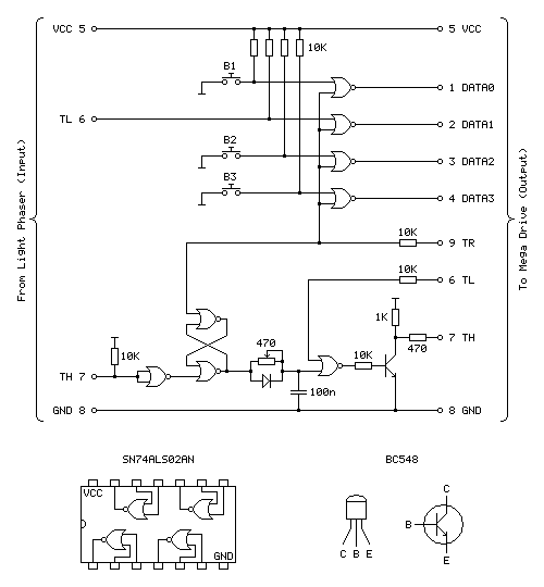
Both modifications show the same thing: a latch gun’s interface is one logic line and a time, and anything that produces an edge at the right time on that line is, to the console, a light gun. Volume 5 comes back to that.
2.10 The bench, instrument by instrument
The lab’s instruments are listed in the hub’s lab capability file; the Analog Discovery Pro ADP3450 is the bench scope and logic analyser named for this project (decision D9).
Table 2 — 2.10 The bench, instrument by instrument
| Test | Instrument | What a pass looks like |
|---|---|---|
| Trigger and button contacts | Multimeter, continuity | Clean make and break, no chatter as the trigger is rolled through |
| Cable conductors | Multimeter, flexing each end | Continuous throughout the flex |
| Zapper sensor stage | ADP3450 scope channel, aimed at white then black on a CRT | Line-rate pulse bursts on white; nothing on black |
| GunCon video and sync | ADP3450 two channels: white wire, then BA7071F pin 8 | Composite present; clean sync pulses out |
| GunCon sensor | ADP3450, at the sensor output | Pulses at line rate when aimed at white |
| GunCon 2 buttons and position | PC with the Linux driver, input-event viewer | Each button reports; X and Y move with aim on a CRT |
| Zapper as a whole | NES, CRT, Zap Ruder | Trigger, unplugged and aimed results as in §2.2 |
| Replacement GunCon 3 markers | ADP3450 across the 22 Ω resistor | Current within the LED’s rating; equal between units |
2.11 What could not be verified
- No maker’s service procedure for any home light gun was found; the test order is this dive’s.
- Zapper trigger-pull modification: the circuit-board.de thread could not be read (the site refused automated access).
- Replacement switch part numbers for the Zapper, GunCon and GunCon 2: none published.
- GunCon 3 marker wavelength and drive: not stated for the original units; the replacement’s 850 nm and 22 Ω are its author’s choices.
- The NES port-2 fault rests on one owner’s report on iFixit.
Footnotes
-
tepples, “Zap Ruder: The Zapper test ROM project”, NESdev forums, from 9 September 2011 (version 0.02, 30 September 2011). https://forums.nesdev.org/viewtopic.php?t=8108 (read 2026-10-19). ↩ ↩2
-
NESdev Wiki, “Zapper”. https://www.nesdev.org/wiki/Zapper (read 2026-10-19). ↩ ↩2
-
iFixit Answers, “Zapper gun not hitting anything on screen”, question 755126, answer by James BM (November 2023). https://www.ifixit.com/Answers/View/755126 (read 2026-10-19). ↩
-
Martin Korth (nocash), PSX-SPX, GunCon controller and NPC-103 pinout sections. https://psx-spx.consoledev.net/controllersandmemorycards/ and https://psx-spx.consoledev.net/pinouts/ (read 2026-10-19). ↩ ↩2 ↩3 ↩4 ↩5 ↩6
-
beardypig, “guncon2” Linux driver, README. https://github.com/beardypig/guncon2 (read 2026-10-19). ↩
-
Nolan Nicholson, “GunCon2-MiSTer”, README. https://github.com/NolanNicholson/GunCon2-MiSTer (read 2026-10-19). ↩
-
Nick Bild, “How the NES Zapper REALLY Works”, Hackaday.io, 5 May 2025. https://hackaday.io/project/203034-how-the-nes-zapper-really-works/details (read 2026-10-19). ↩ ↩2 ↩3
-
circuit-board.de forum, “Weniger Zugkraft für den Trigger des Nintendo Zappers (NES/Famicom)”, thread 20964. https://circuit-board.de/forum/index.php/Thread/20964/ (not readable 2026-10-19; listed so it can be read by hand). ↩
-
The Opponent, “GunCon 2 to OpenFIRE Conversion”, 28 July 2025. https://theo.minuspoint.com/2025/07/guncon2-openfire-conversion.html (read 2026-10-19). CC0. ↩
-
BuckoA51, “Lightguns and HDMI mods – GunCon 1 Edition”, VideoGamePerfection, 23 March 2026. https://videogameperfection.com/2026/03/23/lightguns-guncon-edition/ (read 2026-10-19). ↩
-
“A quick teardown of the NES Zapper Lightgun”, Stay Caffeinated, 26 April 2024. https://www.staycaffeinated.com/2024/04/26/light-gun-teardown (read 2026-10-19). ↩
-
DjPolystation, “Guncon3-IR-Emitters: Schematics and printable model for guncon 3 IR emitters”, GitHub, commits of 17 May 2025, CC0-1.0. https://github.com/DjPolystation/Guncon3-IR-Emitters (read 2026-10-19). ↩
-
Famicom World, “NES Zapper on AV Famicom”. https://famicomworld.com/workshop/tech/nes-zapper-on-av-famicom/ (read 2026-10-19). ↩
-
Ben Ryves, “Mega Drive Gun Adaptors”, benryves.com. https://www.benryves.com/products/megadrivegunadaptors (read 2026-10-19). ↩ ↩2
Comments (0)