H&K MP7 · Volume 6
Field Strip, Maintenance and Repair
H&K's own procedures from its 2006 and 2011 operator's manuals, compared where they differ: unloading, stripping into the main groups and the bolt, reassembly and function checks, the cleaning and lubrication schedule, cold and dust, zeroing, the faults table, and NATO's published service life and wear limits
6.1 What the manuals are, and what they permit
Two H&K operator’s manuals for the MP7A1 were found, both in the public storage bucket that mirrors H&K documents:
- The Spanish manual, “Pistola ametralladora MP7 A1 / MP7 A1-KSK, calibre 4,6 mm x 30: Instrucciones para el manejo”, H&K identification number 984 627, a 46-page document whose PDF is dated 3 August 2006.1 It is the fuller of the two, with chapters on cleaning, climate, sight adjustment and the KSK version.
- The English manual, “Close Range Weapon MP7 A1, Caliber 4.6mm x 30, Operators Manual”, a 17-sheet fax copy whose header is dated 8 August 2011.2
Both are user manuals, not armourer’s manuals, and both say so in effect: “The weapon may only be disassembled to the extent described in these instructions.”2 H&K’s armourer-level documents are known only by number: NATO’s description of the MP7 lists a maintenance manual (984628), a spare-parts catalogue (979805) and a short description (984626).3 None of the three was found. Everything below is therefore a user’s procedure, and anything beyond it is marked as armourer’s work, as the manuals mark it.
6.2 Making it safe
Before any handling, both manuals require the weapon to be on safe, the magazine out, and the chamber and bore checked empty.21 The Spanish manual’s unloading sequence is:1
- Set the selector to safe.
- Remove the magazine.
- Draw the bolt fully back, covering the ejection port with one hand, and catch the ejected cartridge.
- Check that the chamber and the bore are clear.
The English manual adds that when the weapon is handed over it must be on safe with the bolt to the rear, and that if the weapon is taken out of service the bolt must be retracted and the chamber checked “and that the barrel bore is clear!“2
6.3 Field strip: the main assemblies
The English manual’s procedure is two sentences long: “Push out both locking pins at the rear of the receiver. Remove the butt stock with backplate, charging handle, bolt and recoil spring to the rear from the receiver.”2 The Spanish manual gives the same steps in more detail:1
- Remove the magazine and make the weapon safe (above).
- Pull out the two retaining pins of the backplate housing and put them in the holes in the stock provided for them; the English manual’s parts key labels these “Storage holes for locking pins”.2
- Draw the stock and its housing rearward out of the receiver. The bolt, the recoil spring and the charging handle come with them.
- To separate the bolt, press the bolt forward against the recoil spring, so that the charging handle’s retaining lug can be unhooked from the guide slot on top of the carrier. The bolt comes off forward.
- Remove the recoil spring.
- Remove the front cover: with the cleaning rod, press in the cover’s retaining tongue in the recess in front of the folding grip, and slide the cover forward off the receiver. The English manual says to press “the clip of the front cover into the recess in front of the folding grip and remove the front cover to the front”.2
That leaves the main assemblies: the receiver with barrel, grip, safety and trigger mechanism; the backplate with buffer, charging handle, stock and stock catch; the bolt with recoil spring and guide rod; the magazine; and the front cover (and, in the Spanish manual’s list, the RSA-S sight).
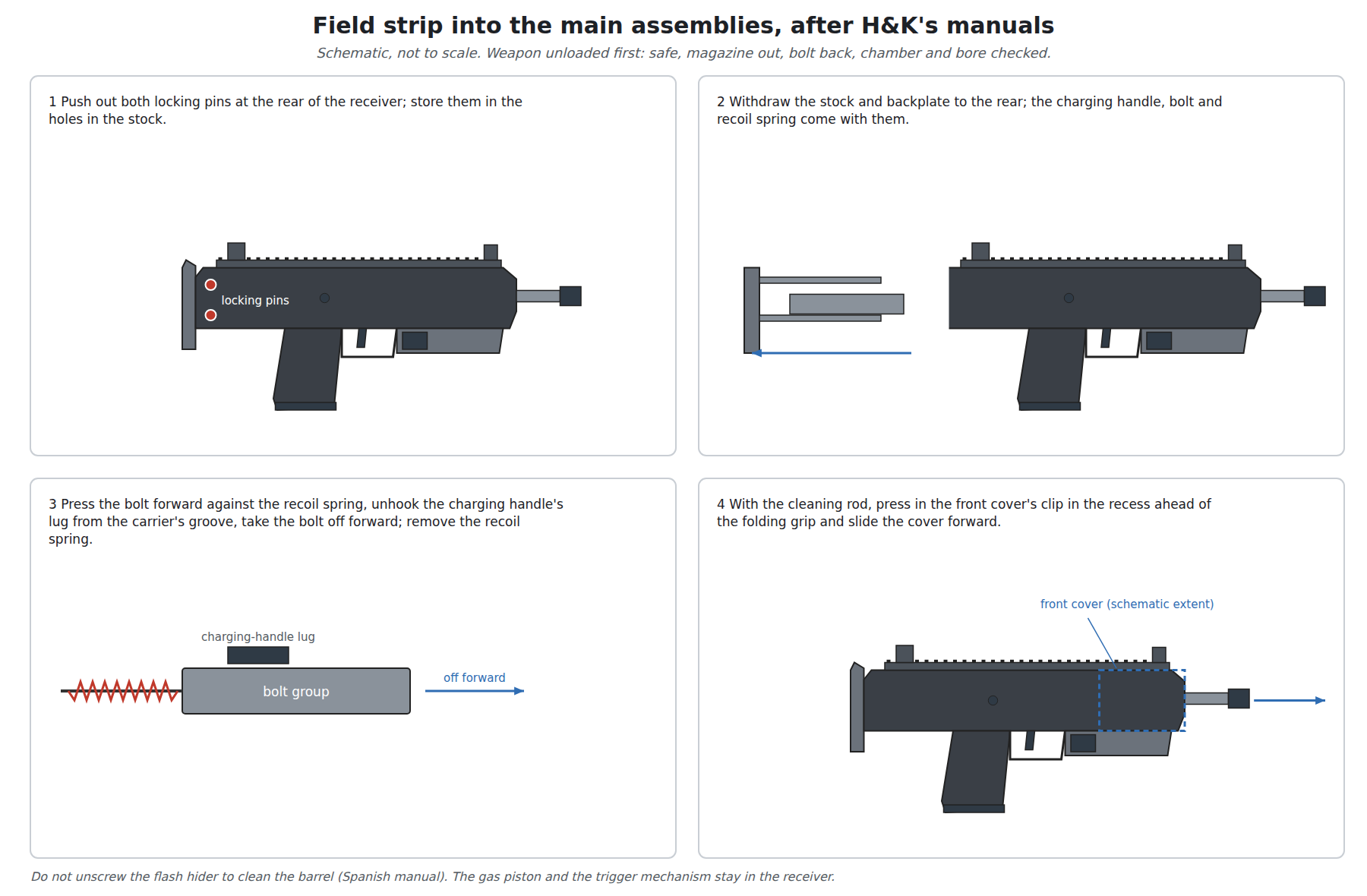
Note what the user does not do. The flash hider stays on the barrel: “the flash hider must not be unscrewed to clean the barrel.”1 The barrel stays in the receiver. The trigger mechanism stays in the receiver. The gas piston is not removed by the user (below).
6.4 The bolt
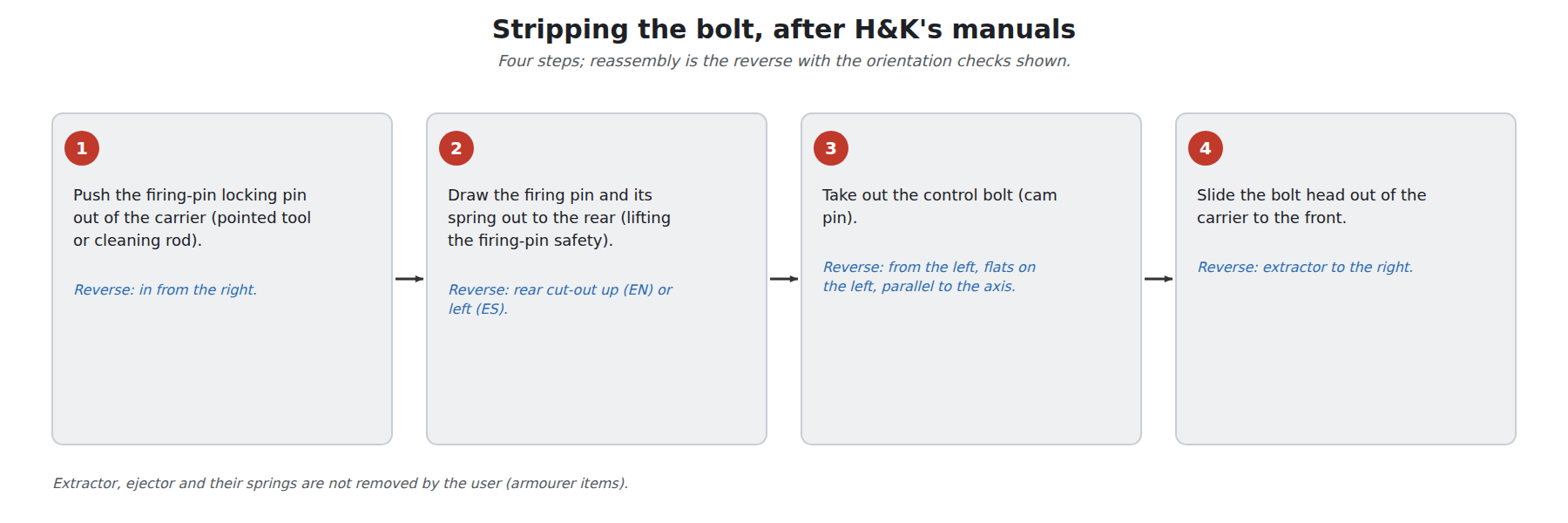
“For cleaning the bolt can be further disassembled.”2 The procedure, from both manuals:21
- Push the firing-pin locking pin out of the bolt carrier with a pointed tool (the Spanish manual says with the cleaning rod, from left to right).
- Remove the firing pin and its spring (the Spanish manual: lifting the firing-pin safety).
- Remove the control bolt (cam pin).
- Remove the bolt head forward, with its extractor and ejector in place.
The extractor and ejector are not removed from the bolt head by the user; both manuals send a damaged extractor, ejector or their springs to the armourer (below).
6.5 The magazine
The magazine has five parts: housing, follower, locking plate, floor plate and spring.2 To strip it, press the locking plate through the hole in the floor plate (the Spanish manual: with the cleaning rod), and slide the floor plate forward off the housing, keeping the bottom covered with the fingers because “the parts are under spring pressure”; then take out the locking plate with the spring and the follower.1
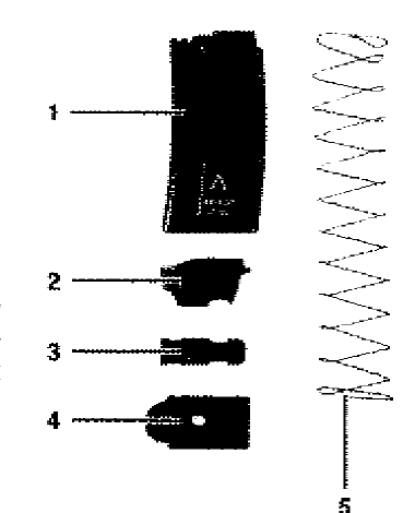
Reassembly is the reverse: follower and spring into the housing, pressed in until the spring is level with the bottom; the locking plate on the spring with its stud outward; the floor plate slid on from the front along its guide rails until the stud engages its hole.2
6.6 Reassembly
The manuals are specific about orientation and order, and the order matters.
- Insert the bolt head into the carrier from the front, extractor to the right.
- Insert the control bolt from the left through the carrier’s guide cam into the head. Its flat surfaces must protrude on the left side of the carrier, parallel to the bolt’s axis; the Spanish manual adds that the firing-pin hole in the head must line up with the hole in the control bolt.
- Insert the firing pin with its spring from the rear, through the carrier, head and control bolt.
- Insert the firing-pin locking pin from the right (English) or fix with the safety pin from right to left (Spanish) all the way.
- Put the recoil spring and guide rod into the carrier, and the spring into its seat in the backplate housing.
- Push the carrier back slightly and engage the charging handle’s lug (English: “the stud on the bottom of the charging handle”) in the groove on top of the carrier.
- Insert the stock assembly and the bolt into the receiver from the rear. The Spanish manual stresses the sequence: the stock’s fork goes in first, then the carrier’s guide grooves onto the receiver’s guideways.
- Push home and fit the two locking pins.
- Slide the front cover on from the front, over the flash hider, until its clip clicks into the recess in front of the folding grip.
The Spanish manual adds a condition the English one omits: “When inserting the bolt into the receiver, the hammer of the trigger mechanism must be cocked; if necessary, cock it with the recoil spring.”1 A bolt pushed home over a hammer that has been dropped will not seat properly.
6.7 Function checks
After reassembly both manuals require four checks, with the magazine removed or an empty magazine fitted: that the bolt runs forward and locks when the charging handle is drawn and released; that the safe, single and continuous positions behave correctly; that the bolt catch holds the bolt open on an empty magazine; and that the bolt-catch lever releases it and can lock it open with no magazine.21 Volume 5 sets out what each position must do, because the checks are the clearest published description of the fire-control logic.
6.8 Cleaning
The Spanish manual’s chapter on cleaning is the only detailed one.1 In summary:
- When: after every firing, whenever the weapon is wet or dirty, and after every cleaning a check of condition, movement and function.
- With what: the 4.6 mm cleaning kit, clean patches and cloths, a bore brush and a chamber brush, and a cleaning and preserving agent such as S-761 or MIL-L-46000. The cleaning schedule names the lubricant as “weapon oil S-761 or O-158”.2
- Prohibited: cleaning “with metal objects, or plastic ones such as nylon, perlon and the like”, or with chemicals such as benzine or carbon tetrachloride. (H&K’s 2012 cleaning kit includes a nylon brush; see the conflicts below.)
- Plastic parts may be cleaned with water or soapy water if necessary.
- The barrel: do not unscrew the flash hider. Pass the oiled bore brush through several times, the first time while the barrel is still slightly warm after firing; let the agent work for several hours; brush again; clean the chamber with the oiled chamber brush; then pass dry patches until they come out clean. Lightly oil the bore, the gas block and all other metal parts.
- The magazine: strip, clean and reassemble it.
H&K’s 2012 accessory list gives the contents of the issued cleaning kit, part 209 357: a nylon storage bag, a bore snake, a lens tissue, an oil bottle, a chamber brush, a bronze-wire cleaning brush, an oil brush, a pull-through, a nylon brush and a cleaning rod.4
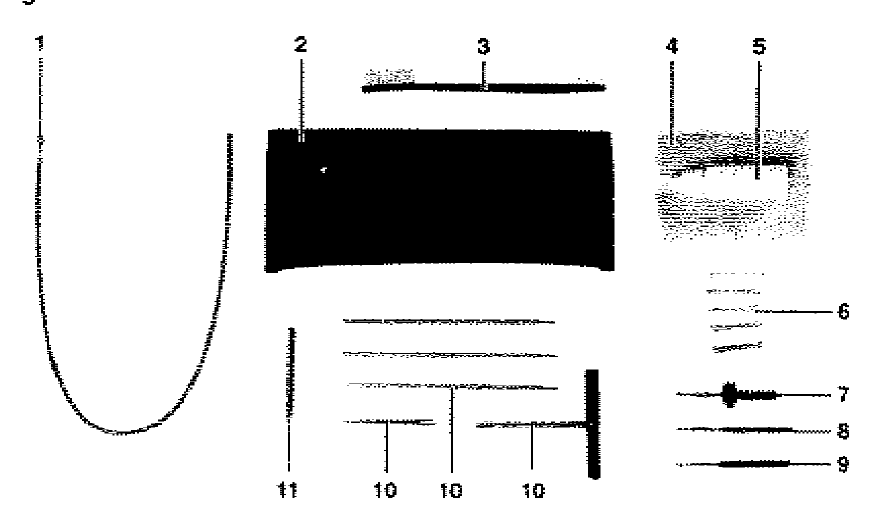
The English manual’s kit has a flexible rod, a case, brushes, a cloth, an oil can, wads, chamber and bore brushes (one brass), a rod with a folding grip, extensions and a wad holder, and a cross pin for the rod’s grip.2
6.9 The maintenance schedule
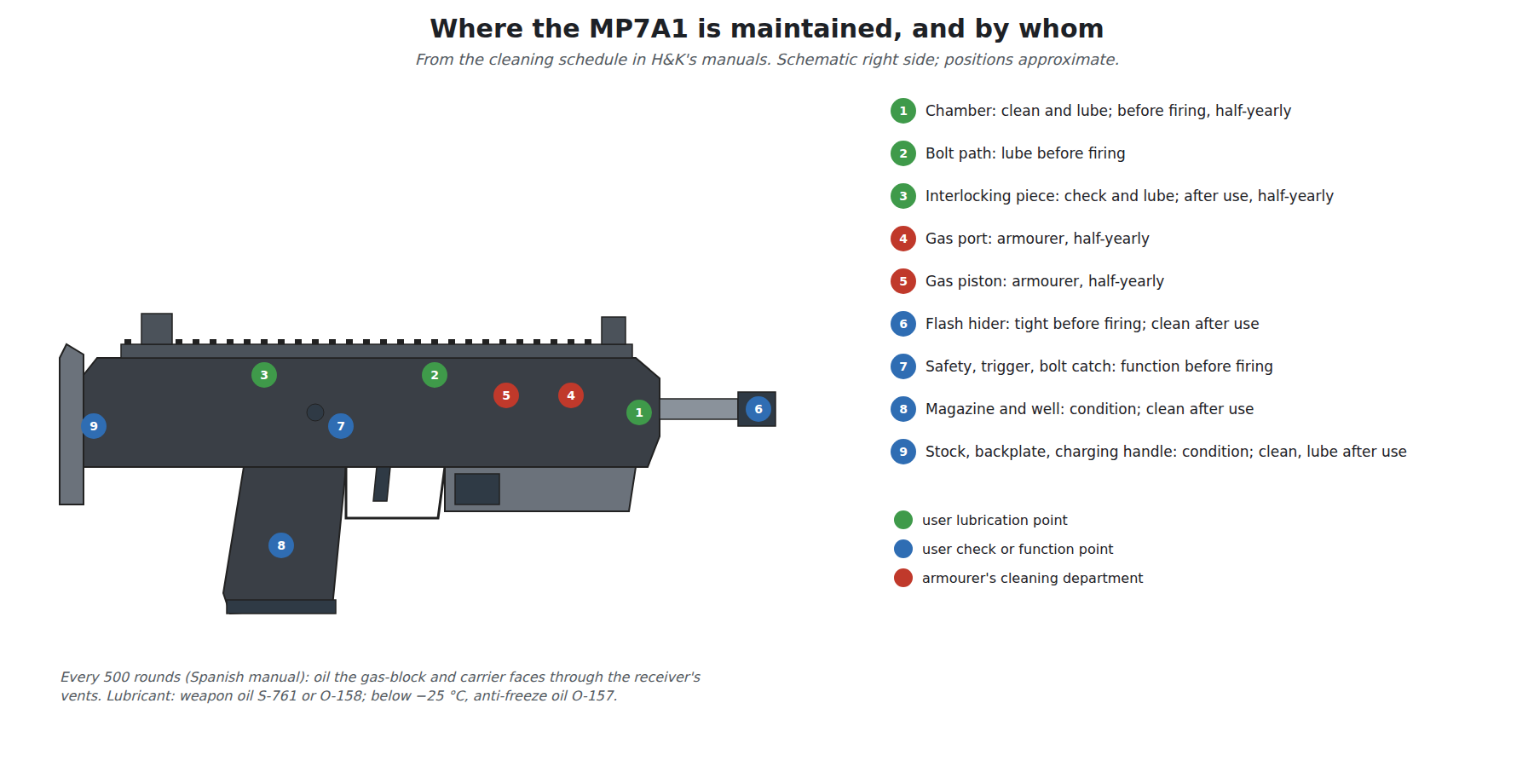
Both manuals carry the same schedule. Its symbols mark each point as a user lubrication point, a user maintenance or function-check point, or a point for the armourer’s cleaning department, and its intervals are p before firing, a after firing or use, and h half-yearly. The lubricant throughout is weapon oil S-761 or O-158.21
Table 1 — The maintenance schedule
| Check point | Who | Activity | Interval |
|---|---|---|---|
| Weapon and accessories | user | check, clean, lubricate | after use; half-yearly |
| Barrel | user | remove oil | before firing |
| Barrel | user | clean, lubricate | after use |
| Chamber | user (lubrication point) | clean, lubricate (brush, rod) | before firing; half-yearly |
| Gas port | armourer | clean, lubricate | half-yearly |
| Receiver | user | clean, lubricate | after use |
| Bolt path | user (lubrication point) | lubricate | before firing |
| Interlocking piece | user (lubrication point) | check, lubricate | after use; half-yearly |
| Bolt catch/release lever, safety, trigger | user | function | before firing |
| Flash hider | user | tight fit; clean | before firing; after use |
| Gas piston | armourer | clean, lubricate | half-yearly |
| Magazine release; magazine well | user | function; condition | before firing; and after use |
| Bolt | user | function; clean, lubricate | before firing; and after use |
| Extractor; ejector | user | function | before firing (extractor also after use) |
| Charging handle | user | function of the latch | before firing |
| Recoil spring | user | function | before firing |
| Backplate | user | clean, lubricate | after use |
| Butt stock | user | condition, tight fit | before firing; after use |
| Interlocking; front cover | user | function; condition and fit | before firing |
| Magazine | user | condition; clean, lubricate | before and after use |
| Follower and magazine spring | user | smooth operation | after use |
Source: H&K, English manual (fax 2011), section 6, and Spanish manual (2006), chapter 9; the two agree.21
The schedule’s most important line is the one a user is least likely to expect: the gas port and the gas piston are armourer’s items, cleaned half-yearly, not after every firing. The user does not take the gas system apart.
The Spanish manual adds one recommendation that is not in the table: “after about 500 rounds, oil the interface between the front face of the gas block and the front face of the bolt carrier”, by drawing the carrier back 1 to 2 cm with the charging handle and oiling both faces through the ventilation openings in the receiver.1
6.10 Cold, heat and dust
The Spanish manual’s climate section is short and specific:1
- High humidity, high temperatures and cold down to about −25 °C need no special measures.
- Below −25 °C, lubricate the moving parts with a special anti-freeze oil, for example O-157 (MIL-L-14107).
- Condensation freezes: do not carry the weapon from cold into warmth and soon back into cold. As a precaution, oil the extractor and ejector with anti-freeze oil so that condensation cannot freeze them solid.
- In great heat and heavy dust, lubricate all the sliding surfaces with a suitable lubricant such as S-761 or MIL-L-46000.
6.11 Zeroing the iron sights
The Spanish manual gives the adjustment figures for both sight types.1
Table 2 — Zeroing the iron sights
| Sight | Zeroed at | MPI at 25 m | Elevation | Windage |
|---|---|---|---|---|
| Standard MP7A1 fixed sights | 100 m | about 20 mm below the aiming point | front sight screw: one turn moves the MPI about 45 mm at 25 m; turn “UP” if shooting low | rear notch screw: one click about 7 mm at 25 m; turn L if shooting right, R if shooting left |
| MP7A1-KSK folding sights | 100 m (factory) | about 20 mm below | front-sight nut: one notch about 12 mm at 25 m | rear aperture screw, with a coin or screwdriver |
The standard sights are adjusted with a universal tool with a 2.5 mm angled screwdriver, the rear notch with a coin. The RSA-S reflex sight is also zeroed at 100 m, by its own screws (one graduation 1 cm at 100 m), and the manual reserves that adjustment to an armourer.1
6.12 Faults and their remedies
The manuals’ fault tables agree; the Spanish one has two more lines. Combined, in the manuals’ order and wording:21
Table 3 — Faults and their remedies
| Fault | Cause | Remedy |
|---|---|---|
| Cartridge fails to fire | defective ammunition | wait 5 minutes (Spanish), unload, check the bore is clear; a bullet lodged in the bore: hand in to the workshop at once |
| firing pin damaged or broken | armourer | |
| hammer spring damaged or broken | armourer | |
| Bolt did not open after firing | case jammed in the chamber (deformed case or fouled chamber) | unload, retract the bolt, eject the case, check the bore, clean the chamber |
| Case not extracted or ejected | fouled chamber | clean the chamber, check the bore |
| extractor or its spring damaged or broken | armourer | |
| ejector or its spring damaged | armourer | |
| insufficient bolt recoil | unload, retract the bolt, remove the case, check the bore and the bolt’s movement, clean | |
| case rim (English: base of case) ruptured | drive the case out with the cleaning rod | |
| Bolt fails to feed | magazine not inserted properly | insert it properly |
| magazine loose | check the magazine catch and the magazine’s engagement stud; armourer if needed | |
| magazine spring weak | change the magazine; send the faulty one to the armourer | |
| magazine lips damaged | change the magazine; send the faulty one to the armourer | |
| Bolt not fully closed; cartridge not fully chambered | fouled chamber | clean it |
| bolt guideways fouled; cartridge damaged | clean the guideways; unload, check the bore | |
| recoil spring weak | armourer | |
| Bolt not held open after the last round | magazine spring weak | change the magazine |
| bolt catch (English: “bolt lock”) damaged | armourer | |
| Cocked hammer does not release | trigger bar broken (Spanish: “uña de retenida”, the retaining pawl, broken) | armourer |
| Magazine jams in the well | magazine damaged | change it |
| magazine catch damaged | armourer | |
| (Spanish) well or magazine dirty | clean | |
| (Spanish) Group shifted sideways | rear sight out of adjustment | readjust the notch |
| (Spanish) Group shifted vertically | front sight out of adjustment | readjust the front sight |
| (Spanish) Group shifted both ways | different ammunition | re-zero |
Both manuals end the table with the same warning: “Only experienced staff from the armourer’s shop is authorized to clear grave stoppages.”2
6.13 What the armourer does
The manuals assign to the armourer every repair that needs a part replaced, and two routine cleaning tasks. Taking the tables and the schedule together, the armourer’s list is:21
- cleaning and lubricating the gas port and gas piston, half-yearly;
- the firing pin, the hammer spring, the trigger bar (the Spanish manual’s retaining pawl) and the bolt catch;
- the extractor and ejector and their springs;
- the recoil spring;
- the magazine catch, and damaged magazines sent back for repair;
- clearing grave stoppages, including a bullet lodged in the bore;
- adjusting the RSA-S reflex sight;
- fitting the safety blank-firing attachment (Spanish manual).
The manuals do not say how any of those repairs is done.
6.14 Service life and wear limits
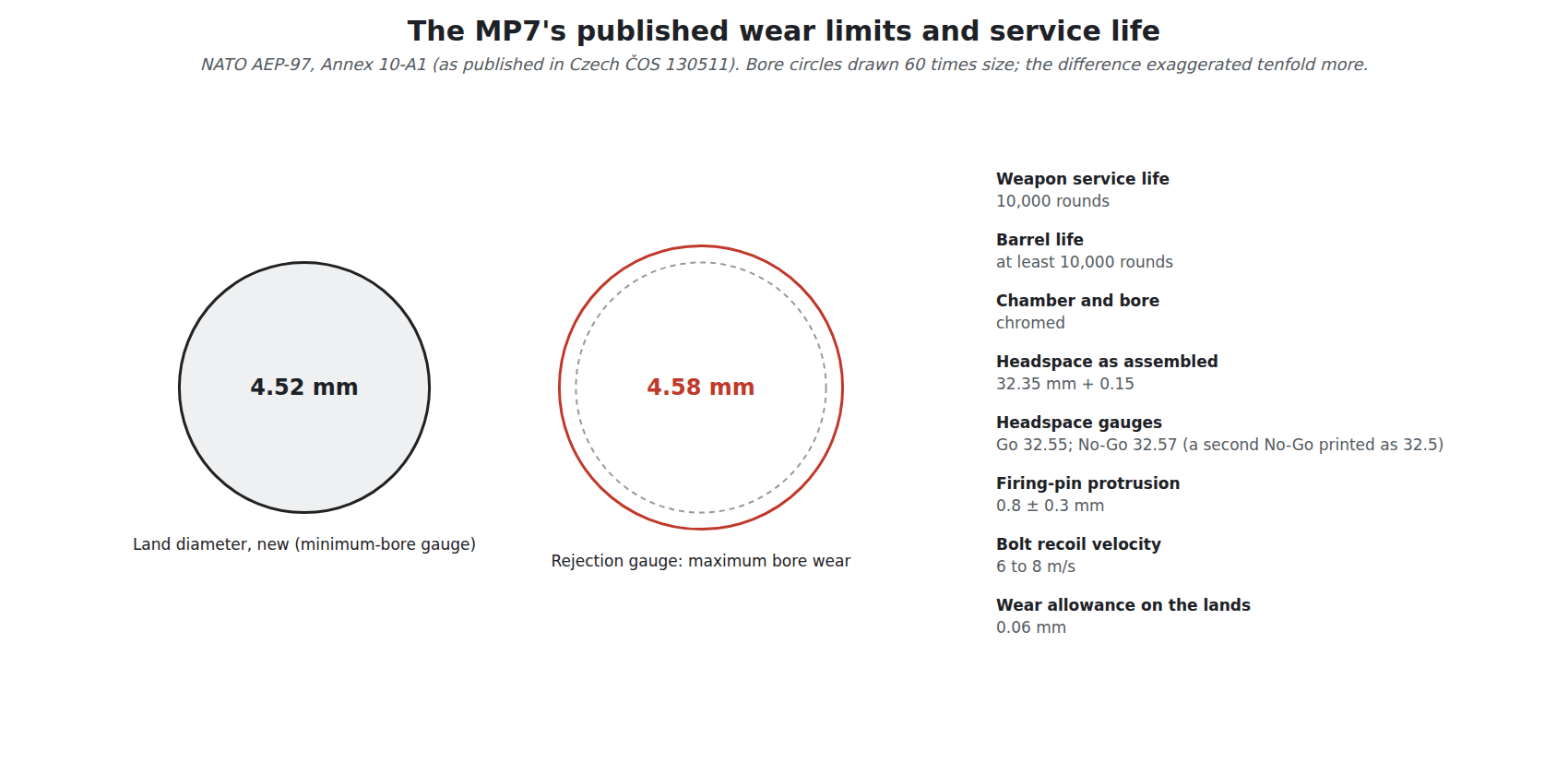
The only published service-life and wear figures for the MP7 are in NATO’s proof manual, which describes the MP7 as the nominated weapon for 4.6 mm ammunition testing.3 It gives:
- Weapon service life: 10,000 rounds.
- Barrel life: at least 10,000 rounds, judged by the criteria of NATO document AC/225-D/14 and/or by bore wear.
- Chamber and bore chromed.
- Gauges, by H&K drawing number: headspace Go 32.55 mm (349867) and No-Go 32.57 mm (349898), with a second No-Go entry printed as 32.5 mm (349976), which cannot be right for a No-Go gauge and is evidently a misprint; firing-pin protrusion (349890); extractor overlap Go and No-Go (350723, 350724); minimum bore diameter 4.52 mm (988423); and maximum bore wear 4.58 mm (349889).
- Headspace as assembled 32.35 mm + 0.15, not adjustable; firing-pin protrusion 0.8 ± 0.3 mm.
The bore figures give a wear allowance: a new bore’s land diameter of 4.52 mm, a rejection gauge at 4.58 mm, 0.06 mm of wear in all.
H&K’s commercial terms add two figures for one customer. The Ministry of Defence announced in 2005 that its MP7s came with “a ten-year manufacturer warranty” and “an expected service life of 15 years”.5
Parts are an armed-forces and police matter: the MP7 is not sold to private buyers (Volume 8), and H&K’s spare-parts catalogue was not found. H&K’s 2012 accessory list gives part numbers for magazines, sights, stocks, slings and the cleaning kit (Volume 7).4
6.15 Detail strip
No published procedure for detail-stripping the MP7, beyond the bolt and the magazine, was found. Neither operator’s manual goes further, both forbid going further, and H&K’s maintenance manual (984628) was not found. In particular, nothing published describes removing the barrel, the gas piston, the trigger mechanism, the selector or the stock catch, or the extractor and ejector from the bolt head.
This dive does not reconstruct those procedures. A correct armourer-level procedure would have to account for at least what the published documents reveal about the weapon: that the hammer must be cocked when the bolt is inserted; that the control bolt and firing pin interlock and have a defined orientation; that the extractor sits on the right of the head; that headspace is fixed at assembly and checked with Go and No-Go gauges; that the chamber and bore are chromed and the bore is gauged for wear; and that the gas port and piston are cleaned only at the armourer level. Those are the facts a procedure would be checked against. They are not a procedure.
6.16 Where the manuals disagree
Three small conflicts between H&K’s own documents, and one apparent one, reported as found:
- The firing pin’s orientation: the English manual says its rear cut-out “points to the top of the bolt head carrier”; the Spanish says the firing pin goes in “with the rear recess to the left”.21
- The firing-pin locking pin: inserted “from the right” (English) or fixed “from right to left” (Spanish); pushed out “to the right” (English) or “from left to right” (Spanish). These agree on the direction of removal and installation from opposite viewpoints, and are given here so that a reader comparing the two is not misled.
- Nylon: the Spanish manual prohibits cleaning with nylon or perlon objects; H&K’s 2012 cleaning kit contains a nylon brush.14
- The blank-firing attachment: the English manual says it is “fitted onto the flash hider”; the Spanish manual says the SMPG is screwed onto the barrel “in place of the flash hider” with an 11 mm wrench. H&K’s 2012 list has two devices, a “Safety blank firing attachment (SBFA) — for assembling on flash hider” and a “Blank firing attachment (BFA) — Bundeswehr variant”, which may explain it (Volume 7).214
6.17 What could not be verified
- H&K’s MP7 maintenance manual (984628) and spare-parts catalogue (979805).
- Any detail-strip procedure; any armourer’s course content.
- Replacement intervals for springs, extractor or firing pin (none published in the documents found).
- The meaning of the second No-Go headspace figure (32.5 mm as printed).
- Current H&K service terms for military and police customers.
References
Footnotes
-
Heckler & Koch, “Pistola ametralladora MP7 A1 / MP7 A1-KSK, calibre 4,6 mm x 30: Instrucciones para el manejo”, ident. no. 984 627 (PDF dated 3 August 2006), chapters 4, 7–14 and 15, https://s3.amazonaws.com/hk-manuals/files/Military/MP7/MP7A1_Instruction_Manual_Spanish.pdf , accessed 2026-10-18 (translated). ↩ ↩2 ↩3 ↩4 ↩5 ↩6 ↩7 ↩8 ↩9 ↩10 ↩11 ↩12 ↩13 ↩14 ↩15 ↩16 ↩17 ↩18 ↩19 ↩20 ↩21 ↩22 ↩23
-
Heckler & Koch, “Close Range Weapon MP7 A1, Caliber 4.6mm x 30, Operators Manual”, fax copy dated 08/08/11, sections 3, 5–9 and accessories, https://s3.amazonaws.com/hk-manuals/files/Military/MP7/MP7A1_Operators_Manual.pdf , accessed 2026-10-18. ↩ ↩2 ↩3 ↩4 ↩5 ↩6 ↩7 ↩8 ↩9 ↩10 ↩11 ↩12 ↩13 ↩14 ↩15 ↩16 ↩17 ↩18 ↩19 ↩20 ↩21 ↩22 ↩23
-
ČOS 130511, 1st ed. (STANAG 4823 / AEP-97(A)), Prague 2023, Annex 10-A1, sections 10-A1.1 to 10-A1.10, https://oos-data.army.cz/cos/cos/130511.pdf , accessed 2026-10-18 (translated). ↩ ↩2
-
Heckler & Koch, “accessories programme MP7 A1 4.6 mm x 30”, v003.09.12, https://s3.amazonaws.com/hk-manuals/files/Military/MP7/MP7A1_Accessories.pdf , accessed 2026-10-18. ↩ ↩2 ↩3 ↩4
-
Ministry of Defence, “Ministry of Defence Police to get new specialised firearm”, 2 March 2005, https://www.wired-gov.net/wg/wg-news-1.nsf/54e6de9e0c383719802572b9005141ed/1f8a563335d39e2b802572ab004bae22 , accessed 2026-10-18. ↩
Comments (0)