H&K MP7 · Volume 5
How It Works: A Short-Stroke Piston and a Six-Lug Rotating Bolt in a Pistol-Sized Gun
The cycle of operation part by part from H&K's operator's manuals, the NATO proof manual's figures for the mechanism, why a gas-operated locked breech suits a cartridge this small, and the controls, stock, grip and magazine
5.1 The system in one paragraph
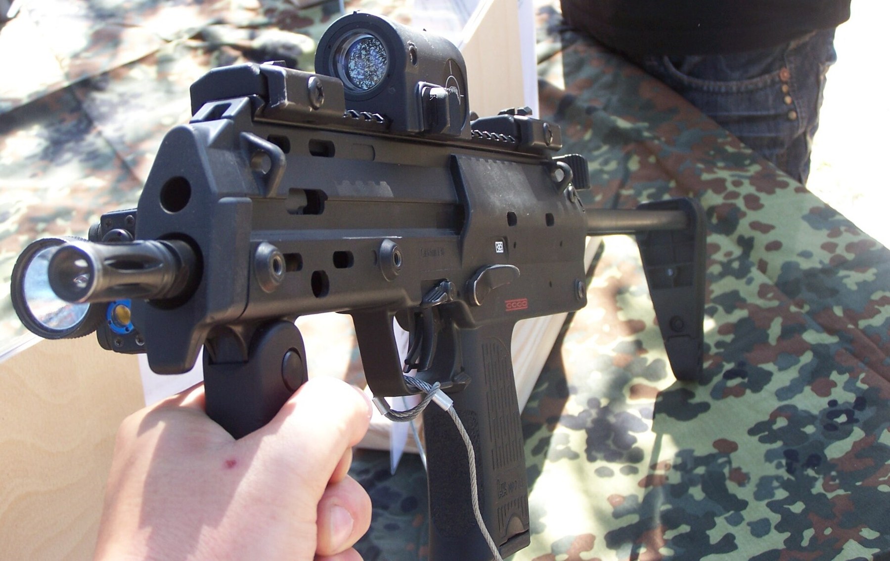
H&K’s current product page lists the MP7’s operating principle as “Indirect gas-operated” and its bolt system as “Locked rotating bolt head”.1 Its English operator’s manual says the same at more length: “Gas operated, firing from a closed bolt, rotary, 6-lug bolt head”, with a “Short stroke piston. The gas operating system does not require any manual gas adjustment.”2 Gas tapped from the barrel drives a short piston that strikes the bolt carrier; the carrier’s rearward travel rotates and unlocks the bolt head; the bolt extracts and ejects, compresses a recoil spring, and returns to feed, chamber and lock the next round. A hammer fires it. Small Arms Review reported in 2000 that the short-stroke system was said to be similar to that of H&K’s G36 rifle,3 and the MP7 is, in layout, a short-stroke rifle mechanism scaled to a pistol cartridge and folded around a magazine in the grip.
5.2 Why a small cartridge got a locked breech
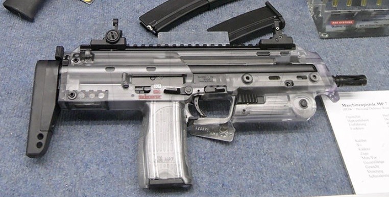
Submachine guns firing pistol cartridges are usually simple blowback weapons: the bolt is not locked, and its mass and spring alone hold the case in the chamber until pressure falls. The FN P90 is one, firing the 5.7×28 from a closed bolt.4 The 4.6×30 would seem a natural candidate for the same treatment.
H&K chose otherwise, and gave its reason in 2000. Its PDW presentation compares “Low recoil impulse (Bolt face impulse)”: “Gas operated locked breech HK PDW 4.6 x 30 mm: 1.93 N/s [sic]” against “Blowback operated unlocked breech FN P90 5.7 x 28 mm: 3.94 N/s”.5 The figures are H&K’s and the comparison is with a competitor, but the principle is sound. In a blowback gun the bolt’s mass is what resists the case; the heavier the cartridge’s thrust, the heavier the bolt must be, and its whole momentum arrives at the shooter’s shoulder or hand. In a locked-breech gun the case is held by lugs, and the bolt can be light because it only has to cycle, not to resist. The 4.6×30 runs at up to 4,000 bar (Volume 3), a rifle-class pressure in a pistol-class case, and the MP7 had to be light enough to be fired with one hand. A locked breech lets a small, light weapon handle a high-pressure cartridge with a light, fast-moving bolt. NATO’s proof manual gives that bolt’s rearward speed: 6 to 8 m/s.6
5.3 The main assemblies
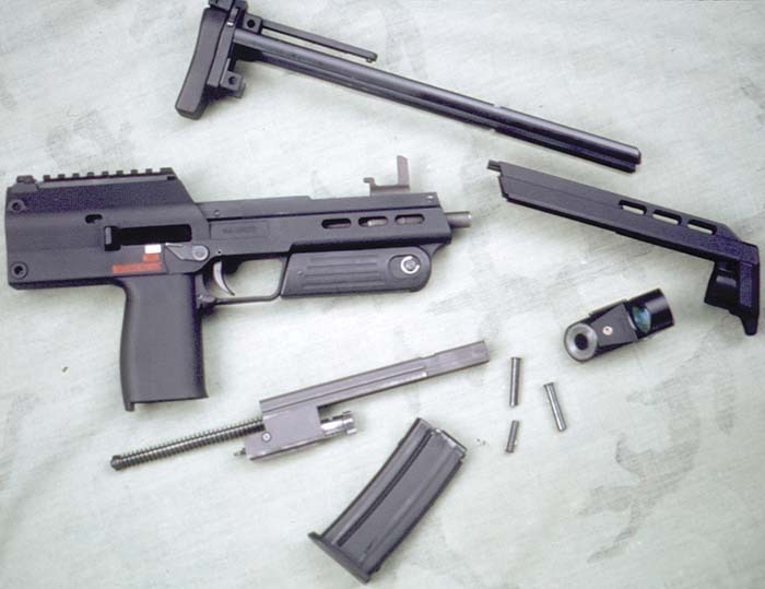
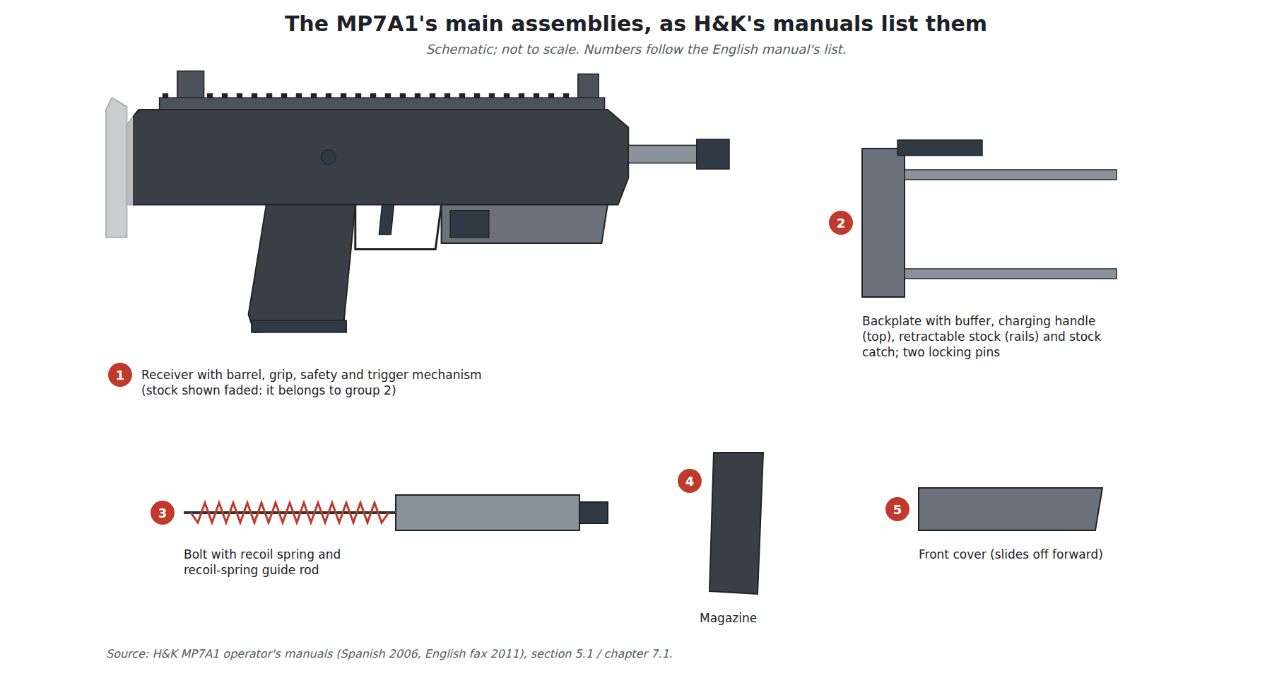
H&K’s manuals divide the weapon, for cleaning, into five groups. In the English manual’s words:2
- Receiver “with barrel, grip, safety and trigger mechanism”.
- Backplate “with buffer, charging handle, retractable butt stock and butt stock locking mechanism”.
- Bolt “with recoil spring and recoil spring guide rod”.
- Magazine.
- Front cover.
The Spanish manual groups them slightly differently, listing the receiver complete, the stock complete, the bolt complete, the magazine and the RSA-S sight, and calls the backplate the caja de fijación, the locking housing.7 H&K Inc.’s 2000 presentation describes the housing as “One-piece polymer housing”, with “End cap”, “Retractable buttstock” and “Disassembly pins”.5 The receiver is polymer; the barrel, the bolt and the rails are steel and aluminium.
The arrangement is what makes the gun short. The barrel sits high, the bolt runs directly behind it inside the top of the receiver, and the stock’s two rails slide forward alongside the receiver on either side of the bolt’s path when collapsed. The magazine, in the grip, feeds upward into the bolt’s path ahead of the hand.
5.4 The bolt group
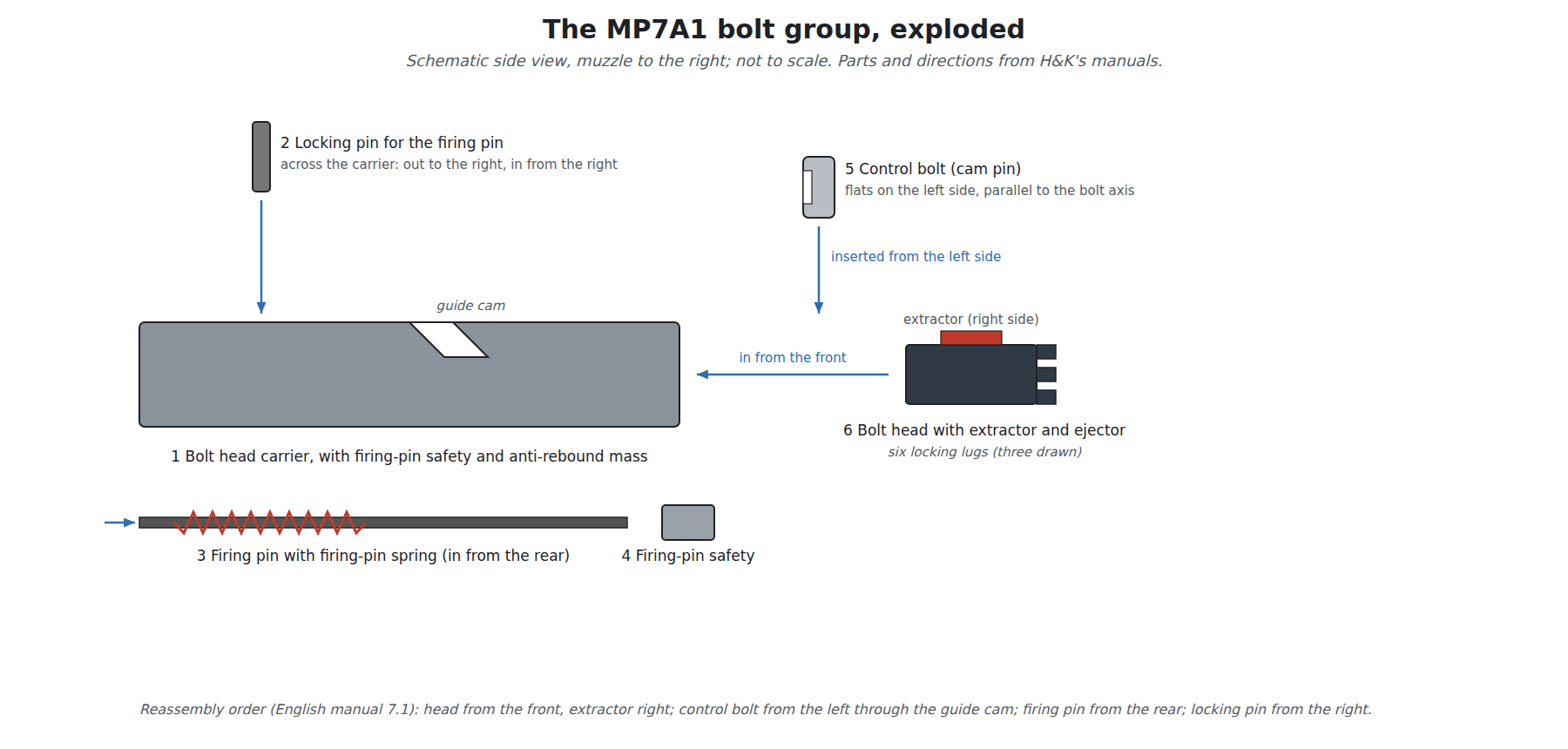
The manuals name the bolt’s parts, in the English text’s order:2
- Bolt head carrier “with firing pin safety and anti-rebound mass”.
- Locking pin for firing pin (the Spanish manual’s “perno de seguridad para percutor”).
- Firing pin with firing-pin spring.
- Firing pin safety (“seguro del percutor”).
- Control bolt (Spanish “perno de guía”, guide pin), the cam pin.
- Bolt head “with extractor and ejector”.
What each does follows from where it sits, and from the reassembly instructions, which are explicit about orientation.27
The bolt head carries the six locking lugs, the extractor (fitted “to the right”) and the ejector. It slides into the front of the carrier and is free to rotate in it.
The control bolt passes “from the left through the guide cam of the bolt head carrier into the bolt head”, with its flat surfaces protruding on the left and parallel to the bolt’s axis; the Spanish manual adds that the firing-pin hole through the bolt head must line up with the hole through the control bolt. The control bolt is the link between the carrier’s straight travel and the head’s rotation: it is fixed in the head and rides in a cam slot in the carrier, so that as the carrier moves the first few millimetres back, the slot drives the pin, and the head, round.
The firing pin runs from the rear of the carrier, through the carrier, the control bolt and the bolt head, and is held by the firing-pin locking pin pushed across the carrier. Because it passes through the control bolt, the control bolt cannot fall out while the firing pin is in place, and the firing pin cannot be fitted unless the control bolt is correctly aligned: the same interlocking-pin arrangement used in many rotating-bolt rifles.
The firing pin safety and the anti-rebound mass in the carrier are named but not described in either manual. Their names say what they are for: a firing-pin safety that stops the pin reaching the primer except when the action is closed, and a mass that damps the carrier’s bounce when it slams forward, which matters in a light bolt cycling at 950 rounds a minute. How they do it is not published, and this dive does not guess.
The extractor and ejector are both spring-loaded, by NATO’s description of the weapon.6 A spring-loaded ejector in the bolt head, rather than a fixed ejector in the receiver, throws the case to the right as soon as the case mouth clears the chamber.
5.5 The gas system
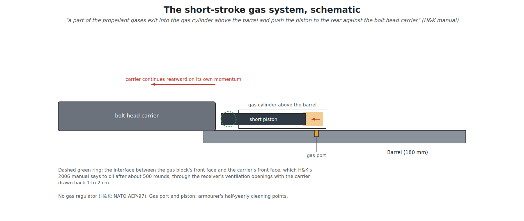
The manuals describe the gas system in one sentence: “After the bullet has passed the gas port in the barrel, a part of the propellant gases exit into the gas cylinder above the barrel and push the piston to the rear against the bolt head carrier.”2 The cleaning schedule names the parts, the “gas port” and the “gas piston”, and makes both an armourer’s job, to be cleaned and lubricated half-yearly (Volume 6).2 There is no gas regulator: “The gas operating system does not require any manual gas adjustment”, and NATO’s description of the weapon records “Gas regulation: no”.26
“Short stroke” means the piston moves only a short distance and hands its momentum to the carrier, which then travels on alone; the piston does not travel with the bolt as it does in a long-stroke system. H&K calls the result “indirect gas-operated”, as distinct from a direct-impingement system that blows gas into the bolt carrier itself.1 The practical consequence is a clean action: the propellant gas is vented forward in the gas block, not into the receiver.
H&K’s Spanish manual adds one maintenance instruction that shows where the piston meets the carrier: “after about 500 rounds we recommend oiling the interface between the front face of the gas block and the front face of the bolt carrier”, by drawing the carrier back 1 to 2 cm with the charging handle and oiling through the ventilation openings in the receiver.7 The piston therefore works between the gas block’s rear face and the carrier’s front face, inside the top of the receiver.
5.6 The cycle, step by step
The English manual’s section headed “Operation of the bolt” describes the cycle in five sentences, quoted here and then expanded:2
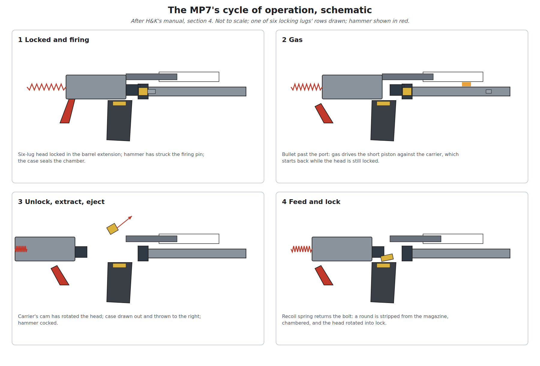
“When the safety is unset and the trigger is pulled, the hammer strikes the firing pin which ignites the primer and the propellant inside the cartridge. The generated gas pressure accelerates the projectile in the barrel. The cartridge case seals the chamber to the rear and is supported by the bolt which locks with 6 locking lugs in the barrel extension. After the bullet has passed the gas port in the barrel, a part of the propellant gases exit into the gas cylinder above the barrel and push the piston to the rear against the bolt head carrier. During its rearward travel the bolt head carrier rotates and unlocks the bolt head which extracts and ejects the cartridge case. During the forward travel of the bolt a cartridge is fed from the magazine into the chamber and the bolt head is locked.”
1. Locked, chambered, cocked. The bolt is forward and its six lugs are engaged in the barrel extension; a cartridge is in the chamber; the hammer is cocked. The weapon fires from a closed bolt.26
2. Firing. The trigger releases the hammer, which strikes the firing pin. The case expands against the chamber walls and seals it; the bolt head, locked to the barrel extension, carries the thrust.
3. Gas. Once the bullet passes the gas port, gas enters the cylinder above the barrel and drives the piston back against the carrier’s front face. The piston’s stroke is short; the carrier takes the impulse and moves back on its own.
4. Unlocking. As the carrier moves, its guide cam drives the control bolt round, rotating the bolt head until its lugs clear the barrel extension. The manual’s wording, “the bolt head carrier rotates and unlocks the bolt head”, is loose: it is the head that rotates, driven by the carrier’s cam. The delay between the carrier starting to move and the head unlocking is what lets chamber pressure fall before the case is pulled.
5. Extraction and ejection. The unlocked head travels back with the carrier, the extractor drawing the case from the chamber; the spring-loaded ejector throws it out of the ejection port on the right, past the case deflector behind the port.2
6. Recoil. The carrier compresses the recoil spring on its guide rod and runs back to the buffer in the backplate, cocking the hammer on the way.2
7. Feeding and locking. The recoil spring drives the bolt forward. The bolt face strips the top cartridge from the magazine and pushes it into the chamber; as the head meets the barrel extension and stops, the carrier’s last few millimetres of travel drive the control bolt round the other way and lock the lugs.
8. Again, or not. On single fire, the hammer is held until the trigger is released and pulled again; on continuous fire, it is released each time the bolt locks, for as long as the trigger is held. If the magazine is empty, the bolt is held open (below).
5.7 Fire control: what the manuals show
The fire-control mechanism is hammer-fired and sits in the receiver above the grip; the manuals name, among its parts, the hammer, the hammer spring and the trigger bar, all as items for an armourer.2 Neither manual describes the mechanism’s internals, and this dive does not go beyond what they publish.
What the manuals do describe is how the controls behave, through the function checks a user must perform after reassembly. With the magazine out and the bolt cycled by hand:2
- On “SAFE” the trigger cannot be pulled and the hammer must not be released.
- On “SEMI AUTO” the hammer is released when the trigger is pulled; if the trigger is held while the bolt is cycled, the hammer is released again only after the trigger is let go and pulled again.
- On “BURST FIRE” the hammer is released when the trigger is pulled, and, while the trigger stays pulled, “the hammer must be released every time the bolt has moved forward and locked”; when the trigger is released the hammer stays cocked.
The last check settles a point of terminology. The English manual’s “BURST FIRE” is continuous automatic fire, not a limited burst: the hammer falls every time the bolt locks for as long as the trigger is held. The Spanish manual calls the same position “Tiro continuo”, continuous fire, and the Bundeswehr’s description of its selector gives “Sicher”, “Einzelfeuer” and “Feuerstoß”.78 No H&K document found describes a limited-burst setting for the MP7.
The trigger itself carries a safety. The English manual’s parts key calls it a “Trigger with safety latch”, the Spanish a trigger “con trinquete del seguro”, with a safety pawl, and H&K’s brochure a “Safety trigger”.279 Its operation is not described; photographs show a separate blade in the trigger face that must be pressed first. NATO’s figure for the trigger pull is 30 to 45 N, the same as H&K’s current page.61
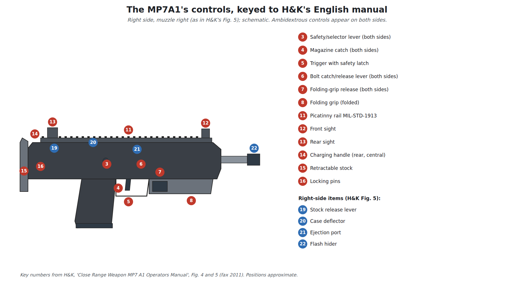
The selector is ambidextrous, with levers on both sides of the receiver above the grip. The Spanish manual lists its positions top to bottom as safe, single and continuous, marked with pictograms (Volume 4).7
5.8 The bolt catch and the last round
“When firing the bolt is arrested in its open position after the last round in the magazine has been fired.”2 The manuals do not describe the linkage, but their troubleshooting tables tie a bolt that is not held open to a weak magazine spring, which indicates that the follower lifts the catch into the bolt’s path when the magazine is empty. The catch is released by the ambidextrous bolt catch/release lever: pressed down, it lets the bolt run forward and chamber a round from a fresh magazine, “without the need to retract and release the charging handle”.2 Pushed up while the charging handle is held back, it locks the bolt open with no magazine in the weapon; the handle can then be pushed forward and latched, and the bolt stays open.2 The Spanish manual’s troubleshooting table gives the two causes of a bolt that is not held open after the last round: a weak magazine spring, or a damaged bolt-catch lever.7
5.9 The magazine
The magazine is a double-column (“staggered”) box that goes into the grip, in 20-, 30- and 40-round sizes.1 The manuals list its parts as housing, follower, magazine locking plate, floor plate and spring, and describe loading it by pushing cartridges alternately under the left and right lips; the Spanish manual adds that the magazine must hold no more than 20 or 40 rounds and that the last cartridge lies against the right lip, “see the mark on the magazine”.27 H&K’s figures for empty weight are about 100 g for the 20-round, 150 g for the 30-round and 200 g for the 40-round magazine.10
Putting the magazine in the grip is the key to the weapon’s size: the grip that a pistol needs anyway holds the cartridges, so no separate magazine well adds length. It brings two penalties, both visible in the manuals. The grip must be deep enough front to back to take a 4.6×30 cartridge’s length; and a 40-round magazine projects well below the hand. The English manual carries a warning about the long magazines: “Do not slam loaded 40 rounds magazines violently into the feed chute, and do not strike the loaded magazines at the bottoms”, because the top cartridge may be thrown from the lips or the lips deformed.2
The magazine catch is ambidextrous and is pushed down with the index finger of the firing hand.2
5.10 The stock, the grip and the charging handle
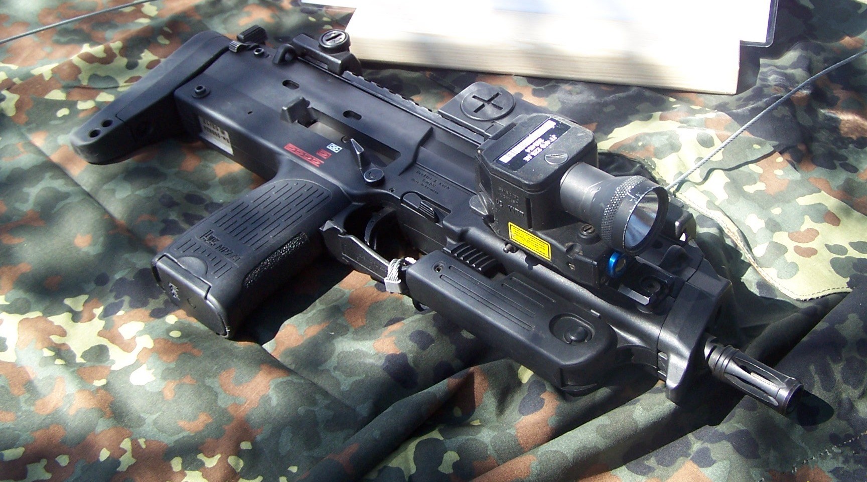
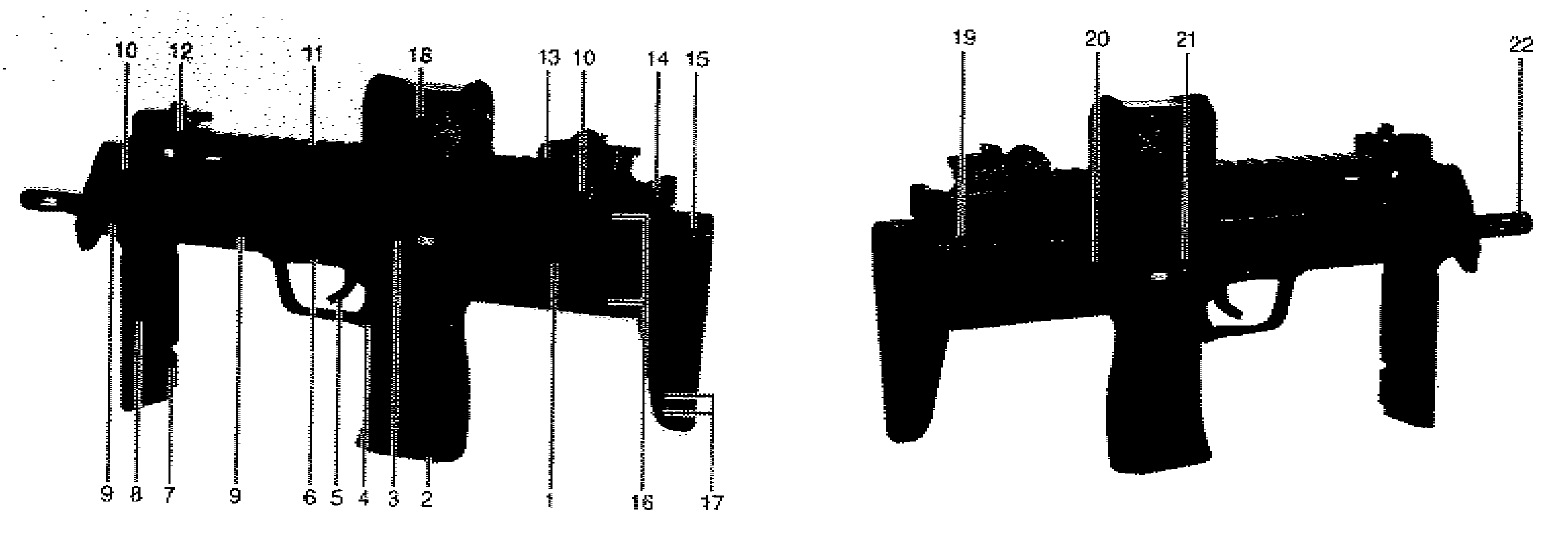
Stock. The stock is a pair of rails ending in a butt plate, which slide into the receiver alongside the bolt’s path. It locks automatically in each position and is released by a lever at the rear of the receiver, on the right; the Spanish manual says the lever is pressed upward.27 The number of positions varies by version (Volume 4). The 2004 H&K cutaway labels a “Rubber buttplate”.11
Folding grip. The MP7A1’s vertical grip folds back under the fore-end. “In its folded position the grip is slightly locked, in its extended position the folding grip is firmly locked”; to fold it, the release is pulled away from the receiver (the Spanish manual: slid downward) and the grip swung back.27 The MP7A2 replaces it with a rail (Volume 4).
Charging handle. “The charging handle is located at the rear of the receiver above the butt stock and locks in its inserted position.” It is squeezed between thumb and index finger and pulled straight back, then released.2 The Spanish manual warns against riding it forward: it “must not be guided by hand”.7 Inside, a stud on the bottom of the charging handle engages a groove on top of the bolt carrier.2 Because the handle is central and behind the sights, it serves both hands equally; H&K’s 2004 cutaway calls it “Ambidextrous cocking lever”.11 H&K offered an extended charging handle as an accessory by 2012.12
5.11 The barrel
The barrel is 180 mm long in every source. H&K gives its bore as a polygonal profile with six grooves and a right-hand twist, the twist being 160 mm (about 1 in 6.3 in).17 NATO’s proof manual records that “the chamber and bore are chromed”, and gives the bore diameters as 4.52–4.54 mm and 4.65–4.68 mm (the Czech text puts the two figures under the opposite headings; the smaller is evidently the land diameter).6 H&K’s 2000 presentation already described the PDW’s barrel as chromium-plated.5
The very fast twist, one turn in 160 mm, is what a light, long-for-its-calibre steel bullet needs to be stable. The polygonal form, which has no sharp land edges, suits a bullet whose steel body must not be engraved (Volume 3). The flash hider is screwed onto the muzzle, is “tightened with a 11 mm fork wrench”, and doubles as the suppressor’s mount (Volume 7); the manual adds that it also “provides protection against gripping the hand over the muzzle”, a point that matters on a weapon this short.2
5.12 The mechanism in numbers
Table 1 — The mechanism in numbers
| Item | Figure | Source |
|---|---|---|
| Operation | gas, short-stroke piston, no regulator | H&K manuals; NATO26 |
| Locking | rotating bolt head, six lugs, in a barrel extension | H&K manual2 |
| Firing | from a closed bolt; hammer | H&K manual; NATO26 |
| Rate of fire | about 950 rounds a minute (H&K); NATO: 950 ± 200 nominal, cyclic recommended 900–950, minimum 800, maximum 1,150; practical rate 210–240 | 16 |
| Bolt recoil velocity | 6–8 m/s | NATO6 |
| Trigger pull | 30–45 N | H&K; NATO16 |
| Firing-pin protrusion | 0.8 ± 0.3 mm | NATO6 |
| Headspace | 32.35 mm + 0.15 (as assembled; not adjustable) | NATO6 |
| Free bullet travel in the leade | 6–10 mm | NATO6 |
| Barrel | 180 mm; polygonal, 6, right-hand; twist 160 mm; chrome-lined chamber and bore | H&K; NATO |
| Service life (weapon and barrel) | 10,000 rounds; barrel at least 10,000 | NATO6 |
5.13 What could not be verified
- How the firing-pin safety and the anti-rebound mass work.
- The fire-control mechanism’s internals (no published manual describes them, and this dive does not reconstruct them).
- The bolt-face impulse figures (H&K’s own, against a competitor, method not stated).
- The bolt’s mass, the piston’s stroke, and the recoil-spring rate.
- Any H&K patent demonstrably covering the MP7’s mechanism (Google Patents refused searches for this dive; see the README).
References
Footnotes
-
Heckler & Koch GmbH, MP7 product page, technical specifications, https://www.heckler-koch.com/en/Products/Military%20and%20Law%20Enforcement/Submachine%20guns/MP7 , accessed 2026-10-18. ↩ ↩2 ↩3 ↩4 ↩5 ↩6 ↩7
-
Heckler & Koch, “Close Range Weapon MP7 A1, Caliber 4.6mm x 30, Operators Manual”, fax copy dated 08/08/11, sections 1, 2, 3, 4, 5, 6, 7, 8 and accessories, https://s3.amazonaws.com/hk-manuals/files/Military/MP7/MP7A1_Operators_Manual.pdf , accessed 2026-10-18. ↩ ↩2 ↩3 ↩4 ↩5 ↩6 ↩7 ↩8 ↩9 ↩10 ↩11 ↩12 ↩13 ↩14 ↩15 ↩16 ↩17 ↩18 ↩19 ↩20 ↩21 ↩22 ↩23 ↩24 ↩25 ↩26 ↩27 ↩28
-
Small Arms Review editorial staff, “HK Unveils New Personal Defense Weapon”, SAR V3N6, March 2000, https://smallarmsreview.com/hk-unveils-new-personal-defense-weapon/ , accessed 2026-10-18. ↩
-
This hub’s FN P90 dive, Volume 1, “A closed-bolt, straight-blowback action”. ↩
-
Jim Schatz, H&K Inc., “HK Personal Defense Weapon”, presentation revised 12/00, https://s3.amazonaws.com/hk-manuals/files/Military/MP7/MP7_Presentation.pdf , accessed 2026-10-18. ↩ ↩2 ↩3
-
ČOS 130511, 1st ed. (STANAG 4823 / AEP-97(A)), Prague 2023, Annex 10-A1, “Characteristics of the MP7 submachine gun, 4.6 mm, nominated by Germany”, https://oos-data.army.cz/cos/cos/130511.pdf , accessed 2026-10-18 (translated). ↩ ↩2 ↩3 ↩4 ↩5 ↩6 ↩7 ↩8 ↩9 ↩10 ↩11 ↩12 ↩13 ↩14 ↩15
-
Heckler & Koch, “MP7 A1 / MP7 A1-KSK … Instrucciones para el manejo” (PDF dated 3 August 2006), https://s3.amazonaws.com/hk-manuals/files/Military/MP7/MP7A1_Instruction_Manual_Spanish.pdf , accessed 2026-10-18 (translated). ↩ ↩2 ↩3 ↩4 ↩5 ↩6 ↩7 ↩8 ↩9 ↩10 ↩11 ↩12
-
Bundeswehr, “Ausrüstung und Technik: Die Maschinenpistole MP7”, https://www.bundeswehr.de/de/ausruestung-technik-bundeswehr/ausruestung-bewaffnung/mp7 , accessed 2026-10-18. ↩
-
Heckler & Koch, “MP7 A1 — Innovation for the future”, brochure (image PDF dated 2007), parts key, https://s3.amazonaws.com/hk-manuals/files/Military/MP7/MP7_Description.pdf , accessed 2026-10-18. ↩
-
Heckler & Koch, MP7 A1 technical-data brochure, Id.-Nr. 978076/V002.02.11, https://s3.amazonaws.com/hk-manuals/files/Military/MP7/MP7A1_Technical_Data.pdf , accessed 2026-10-18. ↩
-
Heckler & Koch GmbH, “Close Range Weapon — From ‘NBW’ to ‘MP7 A1’”, 2 March 2004, cutaway slide, https://s3.amazonaws.com/hk-manuals/files/Military/MP7/MP7_Close_Range_Weapon.pdf , accessed 2026-10-18. ↩ ↩2
-
Heckler & Koch, “accessories programme MP7 A1 4.6 mm x 30”, v003.09.12, https://s3.amazonaws.com/hk-manuals/files/Military/MP7/MP7A1_Accessories.pdf , accessed 2026-10-18. ↩
Comments (0)