High Standard Sentinel · Volume 3
How It Works — Nine Chambers, a Keyhole Ratchet and No Thumb Latch
The full cycle of operation from Sefried's patent and the factory parts sheets: the two-piece frame held together by the hammer pin, the wire part that is both safety and hand pivot, and the ratchet that locks the cylinder by overtravelling
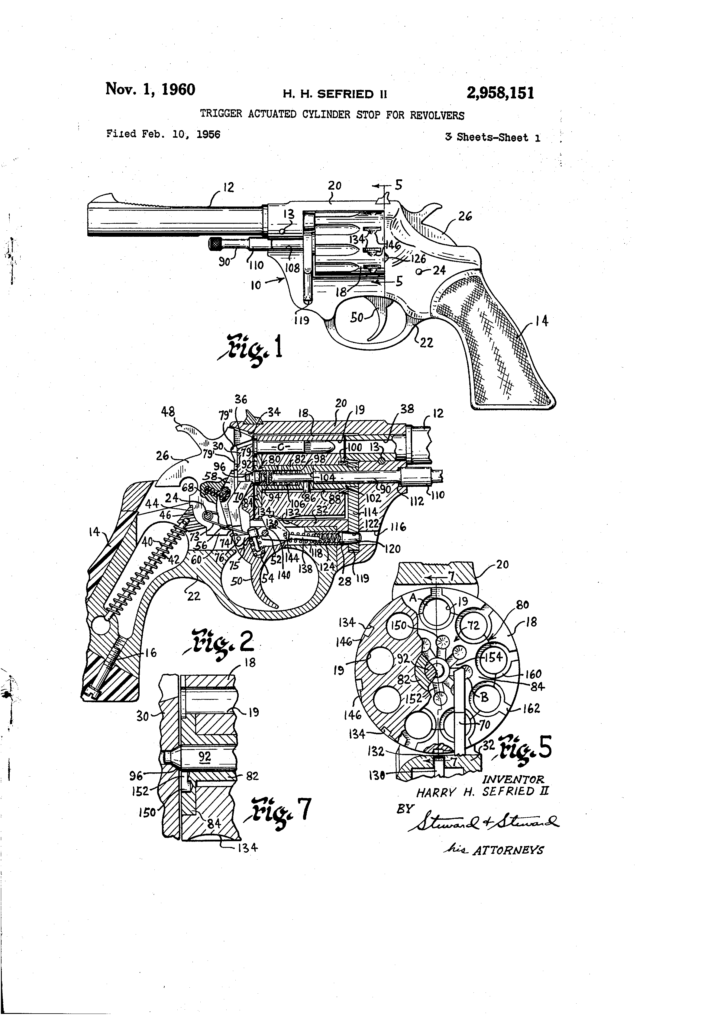
A Sentinel is a conventional double-action revolver in the way a Beetle is a conventional car: everything is where you expect it, and almost none of it is made the way you expect. There is no side plate. There are no leaf springs. There is one screw. The cylinder is released by pushing the ejector rod. The ratchet is a ring of holes. And the whole gun comes apart into four groups when a single pin is driven out — which is also why, as its designer said in 1955, taking one apart is “something Harry does not recommend”.1
3.1 The Sources, and the Patent Nobody Cites
Four documents support this volume, and each is used for what it can carry:
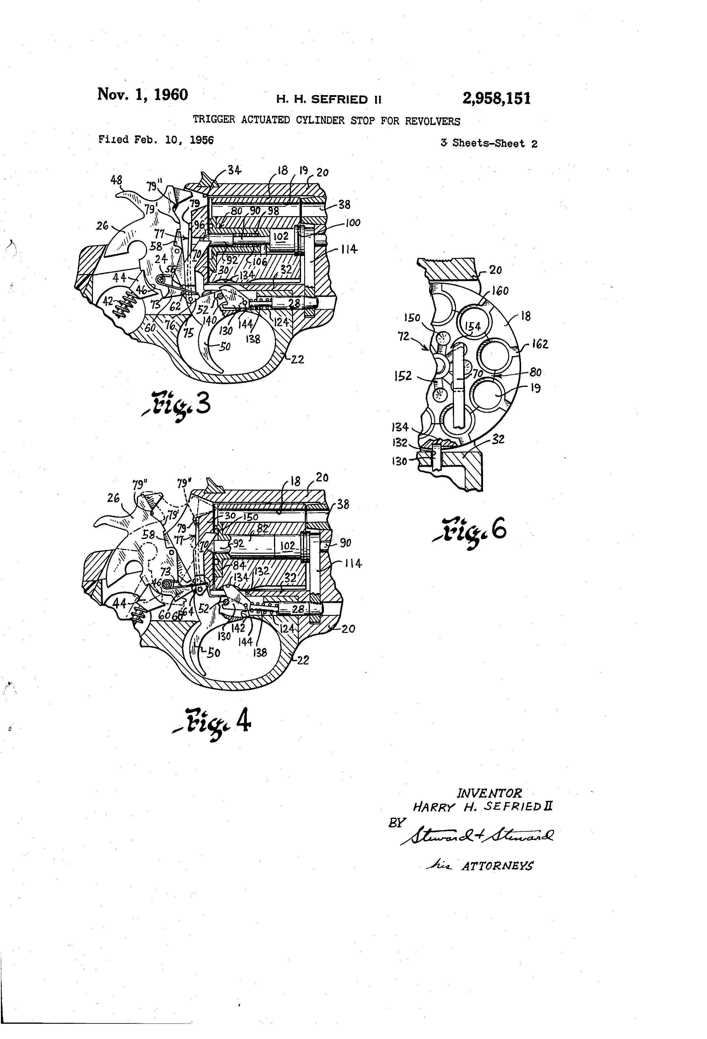
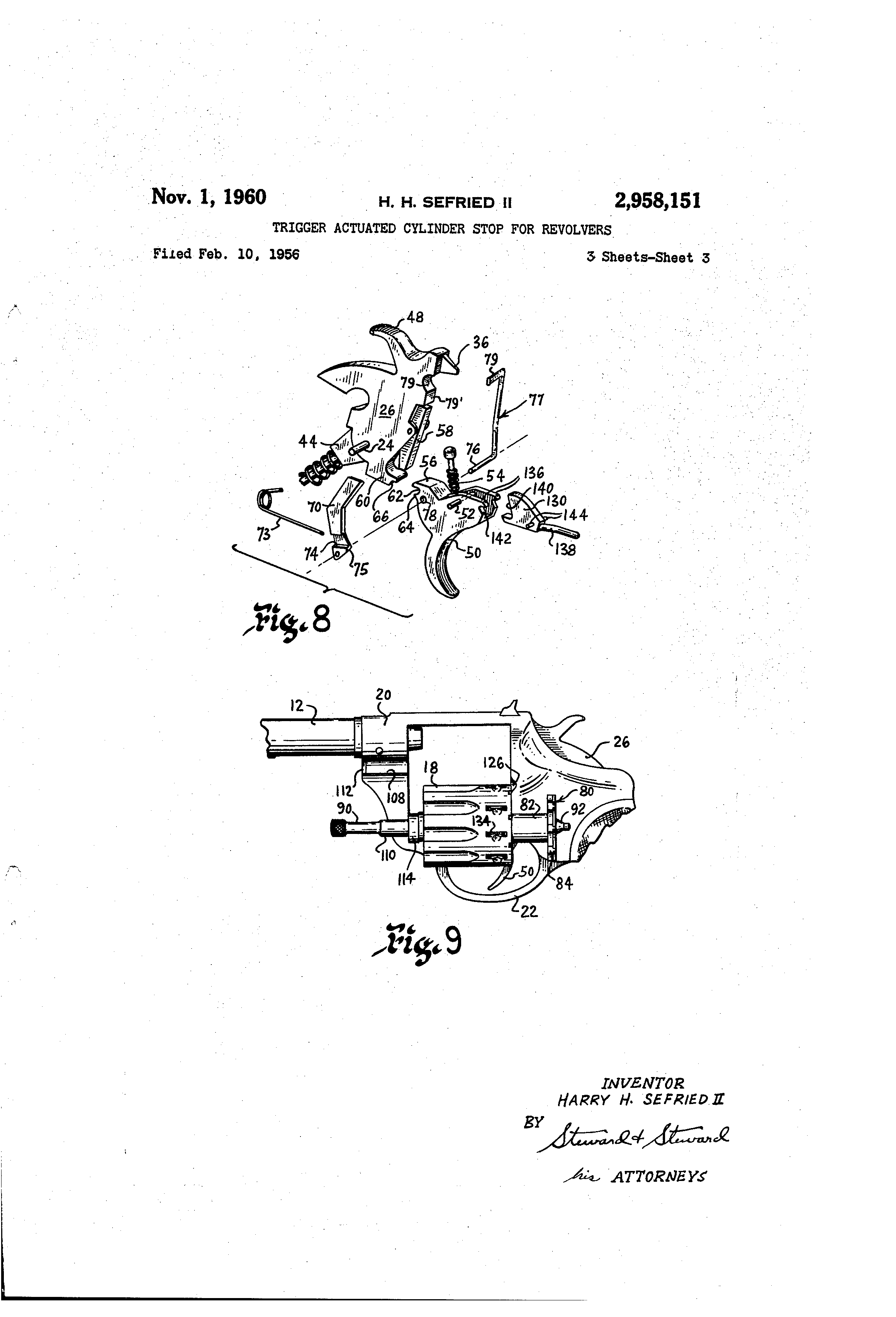
- 🔴 US Patent 2,958,151, “Trigger Actuated Cylinder Stop for Revolvers”, Harry H. Sefried II, “assignor, by direct and mesne assignments, to The High Standard Manufacturing Corporation, Hamden, Conn.”, filed 10 February 1956, granted 1 November 1960.2 Three sheets of drawings showing a Sentinel and about 3,500 words of description. It is the only engineering document on this revolver located anywhere, and the collector literature does not cite it. Reference numerals from it are given below in round brackets.
- William B. Edwards’s account in Guns, June 1955, written from a production gun with the designer beside him — the source for the takedown groups, the springs and the forcing cone.1
- High Standard’s own parts price lists, 1955 to 1974, which name every part and show exploded views.3456
- Ed Buffaloe’s survey, for the changes from series to series.7
The patent also settles a small point of record. Buffaloe writes that “Sefried’s design was never patented”, and in 1955 Sefried himself said of his drilled-hole ratchet, “that’s going to be the basis for a nice little patent”.71 Both statements can now be placed precisely: a patent was filed and granted on the revolver — but its single claim is to the cylinder stop, not to the ratchet. The ratchet is described and drawn in the patent in detail, and left unclaimed.2 So Sefried got his patent; the thing he called “mine” is in it; and the thing the patent actually protects is something else.
3.2 The Architecture in One Paragraph
The frame is in two pieces: an upper housing (20) carrying the barrel, the cylinder window and the standing wall, and a unitary trigger guard and grip frame (22) that fits up into the open bottom of the housing and carries the trigger, the cylinder stop and the hammer spring. The two are joined by two pins: the hammer pivot pin (24) through the middle, which is also the hammer’s axle, and a pin at the front (28), which is also the cylinder crane’s pivot. Knock those two pins out and the revolver becomes four groups — cylinder and crane, trigger guard with grip, barrel and frame, and the lockwork.21 Every spring in it is a coil or a wire spring. There is one screw, and it holds the grip on.
3.3 The Parts, and What They Are Called
High Standard’s names, from the parts sheets, with the patent’s numerals:32
Table 1 — The Parts, and What They Are Called
| Factory part | Patent | What it does |
|---|---|---|
| Frame (7120) | upper housing (20) | barrel, cylinder window, standing wall |
| Trigger guard (7147) | trigger guard and grip (22) | the lower half of the frame; carries trigger and cylinder stop |
| Hammer pivot pin (7132) | (24) | joins the two frame halves and pivots the hammer |
| Hammer (7127) | (26) | nose strikes the rim directly; no separate firing pin |
| Hammer pawl (7129), pin, spring | (58) | the double-action cocking piece, pivoted on the hammer |
| Hammer spring (7135), guide assembly (7154) | (40, 42, 44) | coil spring on a guide rod in the grip |
| Trigger (7145), spring (7150), plunger (7151) | (50, 54) | trigger and its return |
| Hand (7138), hand spring (7139) | cylinder hand (70), wire spring (73) | turns the cylinder |
| Hammer safety stop (7134) | link (77) with stop finger (79) and pin (76) | rebound safety — and the hand’s pivot |
| Cylinder stop assembly (7162) | (130) | locks the cylinder in line with the bore |
| Ejector (7116) | star ejector (80) with ratchet (72) | ejects cases; carries the ratchet |
| Ejector rod (7118) | plunger (90) | the cylinder’s axle, the ejector’s pusher and the cylinder release |
| Crane assembly (7157) | crane link (114), hub (102) | swings the cylinder out |
| Link pivot pin (7140) / the front pin | (28) | crane pivot and front joint of the two frame halves |
Two names invite confusion and are worth fixing now. The hand is the part that rotates the cylinder. The hammer pawl is a different part entirely — it is pivoted on the hammer and is what the trigger pushes on to cock it in double action. Both appear on every parts sheet, and a parts order that mixes them up will arrive wrong.
3.4 Double Action, Step by Step
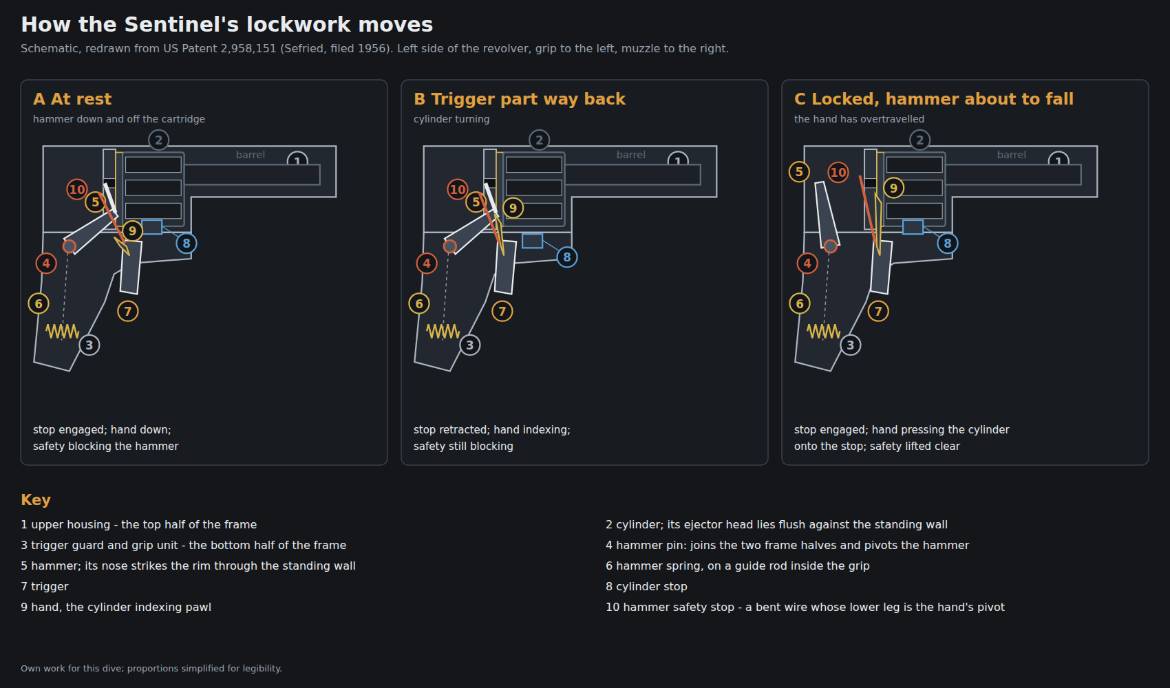
With the hammer down and the cylinder loaded and closed, pulling the trigger does the following, in this order:2
- The cylinder stop retracts. The stop (130) is suspended between the trigger pivot pin (52) at its rear and a spring (124) at its front; as the trigger’s nose goes down, projections on the stop sit in notches in the trigger and carry it down with them, pulling the stop out of its notch in the cylinder.
- The hand rises and begins to index the cylinder. The hand (70), pivoted on a pin that passes through the trigger, engages a slot in the ratchet and starts turning the cylinder.
- The hammer is cocked. The trigger’s cocking finger (56) lifts the hammer pawl (58), rotating the hammer back against its spring; a moment later the hammer’s own foot (60) takes over the lift in a notch (62) in the trigger.
- The cylinder stop is released early, and rides. Part-way through the pull the stop’s projections escape the trigger’s notches and its spring pushes it back up against the cylinder, where it rides on the surface until the next notch comes round.
- The cylinder finishes indexing and the stop drops in. A bevel on the leading edge of each stop notch guides the stop home.
- The hand overtravels and locks. The hand rises past the point of full indexing into the round part of the ratchet recess and, “under the squeeze of the shooter’s finger”, forces the cylinder hard against the stop — taking up every trace of play.
- The hammer falls. Only now does the trigger release the hammer. The patent is explicit about the order: the hand “will be moved into locking engagement in circular recess (150) before the hammer has time to strike the cartridge”.
- The safety clears. With the trigger fully back, the rebound safety’s stop finger has lifted into a recess under the hammer nose, so the hammer can reach the rim.
- The hammer rebounds. Its own spring pushes it back off the cartridge (below).
- Release the trigger and everything resets: the hand drops out of engagement, the hammer pawl snaps back under its spring, the stop stays in its notch, and the safety returns between hammer and standing wall.
3.5 Single Action
Thumbing the hammer back runs the same indexing sequence more slowly, and the hammer’s foot carries a cocking notch (66) that catches a shoulder on the trigger and holds it at full cock. The trigger pull that follows only releases that engagement, which is why the Sentinel’s single-action pull is short and the 1955 press liked it.21
3.6 The Hammer Spring That Returns the Hammer
The hammer spring (40) is a coil around a guide rod (42) in the hollow grip, pressing on a guide head (44) that bears on a convex surface on the hammer’s lower end. The geometry is the clever part, and it does three different things at three points in the cycle:2
- At rest, the head’s full face sits on the hammer’s curve and the spring “does not tend to pivot the hammer in either direction” — the hammer is neutral, not pressed against the cartridge.
- Cocked, only the head’s upper edge bears, so the spring drives the hammer forward.
- At the instant of firing, the hammer overtravels and the contact jumps to the head’s lower edge, on the other side of the hammer pivot — so the same spring now drives the hammer backwards, off the fired case, to its neutral rest.
That is a rebound with no rebound slide, no rebound lever and no second spring. It is the clearest single example of the design rule Edwards described: “throughout the gun, where one part can do the work of two — or three if possible — it is so designed.”1
3.7 One Wire Part, Two Jobs
The hammer safety stop (77) is a piece of heavy steel wire bent twice. Its upper leg (79) stands between a projection on the hammer and the standing wall, positively blocking the hammer from reaching a cartridge unless the trigger is fully back — a rebound safety in the Colt and Smith & Wesson tradition, as Edwards noted.1 When the trigger is fully retracted the leg lifts into a recess cut under the hammer’s nose, letting the hammer through.
Its lower leg is a pin (76) that passes through the trigger and carries the cylinder hand.2 One bent wire is therefore the gun’s drop safety and the pivot its cylinder-indexing hand turns on. Volume 4 draws the obvious maintenance conclusion: this part cannot be neglected, because a worn or sprung safety stop is also a loose hand pivot, and vice versa.
3.8 The Keyhole Ratchet
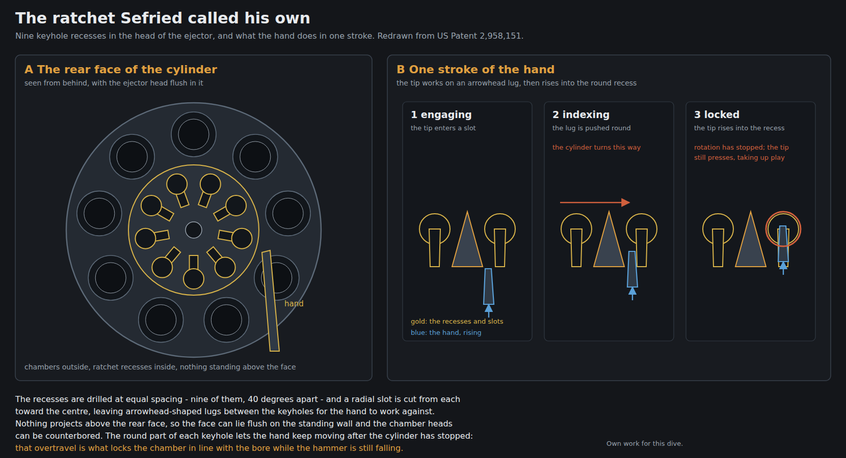
Every other revolver of the period rotates its cylinder with a hand pushing on teeth that stand up from the rear face of the cylinder or ejector star. Sefried’s ratchet is the negative of that. In the patent’s words:2
“A ring of circular recesses (150), equal in number to the number of cartridge chambers, nine in this instance, are drilled at equal distances from the axis of rotation … A slot (152) is cut generally radially toward the center of cylinder from each of the recesses forming a plurality of more or less keyhole shaped depressions which are radially disposed and separated by arrowhead shaped lugs or teeth (154) against which the tip of cylinder hand (70) works.”
The recesses are 40° apart, machined into the head of the star ejector — which is keyed to the cylinder, so for indexing purposes it is the cylinder. The stated manufacturing argument is that the recesses “take the place of the usual ratchet teeth … and are more adaptable to large scale production, since they are more readily machined and do not require individual hand operations”.2
Edwards, from the shooting side, gives the durability argument: ordinary ratchet teeth “are little bumps of metal easily jammed” and burred by a loose hand, “and burrs may actually make the cylinder rotating affair inoperative on other .22s with as many as 9 shots in the cylinder. Not so on the Sentinel. The rotating hand or pawl works inside a little hole … it cannot jam or burr anything.”1 Nine chambers on a .22 cylinder means nine small ratchet teeth crowded into a small circle; deleting the teeth is what made nine shots cheap.
3.9 Why the Overtravel Matters
The patent’s stated purpose is not elegance; it is tolerances. Its opening argument is worth following, because it explains what the Sentinel was for:2
- If only the cylinder stop holds the cylinder in line with the bore, then the stop, its seat in the frame and every stop notch in the cylinder must be machined closely — expensive.
- The usual way round that is to keep the hand pressing on the ratchet after the stop has engaged, so the cylinder is pinched between the two. But then the hammer must fall at exactly the instant indexing completes, “which in turn requires very close tolerances in the cylinder indexing means and firing mechanism, and each gun must be carefully fitted by hand in order to prevent malfunctioning” — more expensive still.
- Sefried’s round recess gives the hand somewhere to keep moving after the cylinder is locked. The trigger can travel further before the hammer drops without anything binding, and all the play is taken up by the hand pressing the cylinder against the stop.
The declared objects of the invention are, in order: accurate indexing and rigid locking “while permitting relatively large machining tolerances in the cylinder stop, the firing mechanism and cylinder indexing means”, and “to provide a revolver which is less expensive to manufacture than are revolvers manufactured heretofore yet functions equally as well”.2 This is a patent about not hand-fitting revolvers, which is exactly what a $35 nine-shot .22 had to avoid.
3.10 The Cylinder: Recessed Heads and Hammer Clearance
Because nothing stands up from the back of the cylinder, its rear face sits flush against the standing wall. Two consequences are designed in:2
- Head spaces (160) — counterbores around each chamber mouth, half of each formed in the periphery of the ejector — take the cartridge rims, so the rims are enclosed by steel on all sides. This is the “counterbored cylinder” of the advertising and the “recessed head cylinder” Edwards praised; the factory’s care instructions add that “because cylinder chambers are counterbored, revolver may be ‘dry-fired’ without injury to cylinder”.4
- Clearance cuts (162) beside each chamber let the hammer nose reach the rim through an aperture (34) in the standing wall.
The hammer strikes the rim directly: the early Sentinel has no separate firing pin, and none appears on any R-series parts list.345
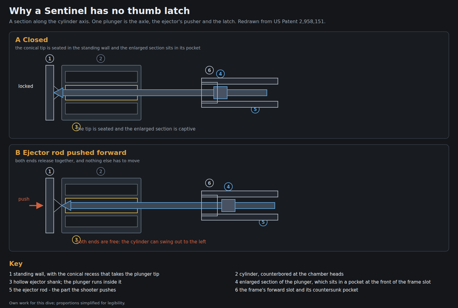
3.11 Opening It: No Thumb Latch
The cylinder release is the Borchardt idea Sefried credited in 1955, and it is the feature that gives the revolver its clean sides.1 The ejector rod is the front end of a plunger (90) that runs the length of the hollow ejector shank and is the cylinder’s axle. It is held at both ends:2
- at the rear, by a conical tip (92) seated in a matching conical recess (96) in the centre of the standing wall;
- at the front, by an enlarged section (110) sitting in a countersunk pocket at the forward end of a slot in the frame’s side.
Push the rod forward against its spring and both ends release at once: the cone comes out of the standing wall and the enlarged section clears its pocket, so the plunger can move sideways out of the slot and the cylinder swings left on the crane. Close the cylinder and a cam slot (126) in the frame pushes the plunger forward again so that the cone can snap back into its recess and the enlarged section into its pocket. One part is the axle, the ejector’s pusher and the latch.
The price of the arrangement is the one ergonomic quirk owners notice: the rod must be pushed forward, and on the earliest guns it had no return spring, so a shooter who forgot to pull it back before closing the cylinder dragged it across the frame. Buffaloe records that this is precisely why the R-102 series of 1961 added an ejector return spring — on earlier guns, “if you didn’t remember to manually retract the ejector into the cylinder before closing you would put a nasty scratch on the left side of the frame”.7 Volume 5 uses that scratch as a dating clue.
3.12 One Pin, Three Jobs
The front pin (28) is the best example of the whole design philosophy. It is at once:21
- the pivot for the cylinder crane link, held into a tapered hole in the link by a spring;
- the front fastening of the trigger guard to the upper frame;
- and the seat of the spring (124) that works the cylinder stop — the same spring doing both jobs.
Edwards described the reassembly consequence in 1955 without naming the pin: “the large plunger, which fits into a hole on the front edge of the guard assembly, is in place with its spring. This plunger positions the guard into the frame at the front, and also serves to lock the cylinder crane in place.”1 To remove the cylinder, the patent says, you push that pin back with “a slender rod or similar tool” through its passage; do that, and the front of the trigger guard is free as well.
3.13 The Forcing Cone
Edwards devotes a paragraph to the barrel’s throat, and it is the one part of the gun described in 1955 in dimensions. Sefried, he says, “has put a hog waller at the end of his barrel that ought to catch a .30 caliber if necessary! It measures about .30 in diameter and tapers to .22 bore diameter in a quarter of an inch.” The result, on a fired gun: “the Sentinel cylinder front shows remarkably little lead splash, unlike many revolvers costing more than twice as much.”1
The reading of the printed figure is the one uncertainty: the scan gives the diameter as an unreadable character, and “.30” is taken from Edwards’s own sentence about catching a .30 calibre bullet. The shape is not in doubt — a long, generously opened lead-in, which on a cheap gun with nine chambers to keep in line is exactly the right place to spend tolerance.
3.14 What Changed Down the Series
Table 2 — What Changed Down the Series
| Series | Change to the mechanism | Source |
|---|---|---|
| R-100 → R-101 (mid-1956) | Hammer and trigger mechanisms “slightly modified … for easier assembly and disassembly”. The 1956 parts sheet carries an inset panel headed “Hammer & Trigger Assembly Parts for Series Model R-100 only” | Buffaloe; parts sheet 990-9378 |
| R-102 (1961) | Ejector return spring added, with a retaining ring and washer | Buffaloe; sheet 997-9974 |
| R-103 | Ratchet changed: “slots milled into the ejector instead of drilled holes” — the nine-hole ratchet “was abandoned in later-production Sentinels” | Buffaloe7 |
| R-109 (1969) | First fully adjustable rear sight in the line | Buffaloe7 |
| Mark I / Mark IV (1974) | Steel frames; .22 WMR in the Mark IV; and a separate firing pin, firing pin spring and retaining pin appear on the parts list for the first time | Buffaloe; parts list 5395176 |
The R-103 change deserves a caveat, because it is the one mechanism claim in this dive that rests on a single secondary source. Buffaloe says the drilled holes gave way to milled slots. The patent shows a ratchet that is both — a round recess with a radial slot cut from it — so “slots instead of holes” most plausibly means the round recesses were dropped and the slots kept, which would remove the overtravel lock described above and return the gun to a conventional pinch between hand and stop. No source located states that explicitly, and no photograph of a late ejector head was found to check it. It is flagged as unresolved in this dive’s README.md.
3.15 What It Does Not Have
A useful way to end. Beside a Smith & Wesson or a Colt of 1955, the Sentinel has no side plate, no cylinder thumb latch, no leaf springs, no separate firing pin (until 1974), no ratchet teeth, no grip frame separate from the trigger guard, and no screws except the one holding the grip. What it has instead is two pins, a bent wire, a ring of holes and a plunger that does three jobs — which is how nine shots and a swing-out cylinder were sold for thirty-five dollars.
Volume 4 takes the same mechanism from the other end: what the owner is allowed to take apart, what wears, and what a gunsmith has to do when the timing goes.
References
Footnotes
-
William B. Edwards, “The First New Revolver in 50 Years”, Guns, June 1955, pp. 6–7 and 37, from https://web.archive.org/web/20120505205714/http://www.gunsmagazine.com/1955issues/G0655.pdf , retrieved 2026-09-19. ↩ ↩2 ↩3 ↩4 ↩5 ↩6 ↩7 ↩8 ↩9 ↩10 ↩11 ↩12
-
US Patent 2,958,151, “Trigger Actuated Cylinder Stop for Revolvers”, Harry H. Sefried II, assignor to The High Standard Manufacturing Corporation; filed 10 February 1956, Ser. No. 564,729; granted 1 November 1960; one claim. Full text and drawing sheets from https://patents.google.com/patent/US2958151A/en , retrieved 2026-09-19. ↩ ↩2 ↩3 ↩4 ↩5 ↩6 ↩7 ↩8 ↩9 ↩10 ↩11 ↩12 ↩13 ↩14 ↩15
-
The High Standard Manufacturing Corporation, parts price list 990-55, “.22 Caliber Model ‘R’ — ‘SENTINEL’”, undated, from https://www.histandard.info/manuals/hprevolvers/ . ↩ ↩2 ↩3
-
The High Standard Manufacturing Corporation, parts price list 997-99, “Model R102 …”, 1/61, same archive. ↩ ↩2 ↩3 ↩4
-
The High Standard Manufacturing Corporation, parts price list 5509, “Sentinel Deluxe Model R-106”, 1965, same archive. ↩ ↩2
-
High Standard Sporting Firearms, parts breakdown 53951, “Mark I Sentinel / Mark IV Sentinel”, 4/74, same archive. ↩ ↩2
-
Ed Buffaloe, “The High Standard Sentinel Revolver”, Unblinking Eye, https://unblinkingeye.com/Guns/Sentinel/sentinel.html , consulted 2026-09-19. ↩ ↩2 ↩3 ↩4 ↩5 ↩6 ↩7 ↩8
-
The High Standard Manufacturing Corporation, parts price list 990-93, “Models R-100, R-101 Blued and Deluxe Nickel”, 6/56, same archive. ↩
Comments (0)