Air and Blowback · Volume 2
Compressed-Air Recoil from Industrial Parts
A compressor, a receiver tank, a regulator, a 24 V three-port valve and a 10 or 16 mm cylinder: SMC's published figures for each, why the valve's orifice and not its response time sets the kick, how much air a shot uses, how to drive the valve from the carrier, where the noise comes from, and how to keep it working
2.1 How it works, block by block
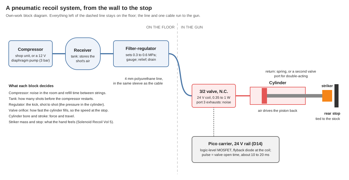
One shot, in order:
- The firmware decides to fire (trigger, autofire rate, ammo count) and switches the valve coil on.
- The valve’s armature lifts within about 5 ms (section 2.2). Air from the line flows from port 1 to port 2 into the cylinder’s cap end.
- Pressure rises in the cylinder until it overcomes the seal friction and any return spring, and the piston accelerates. How fast it accelerates depends on how fast the valve can refill the growing volume behind it (section 2.4).
- The striker hits the rear stop. That impact is the kick, exactly as with a solenoid (Solenoid Recoil Vol 5).
- The firmware switches the coil off. The valve closes port 1 and connects port 2 to port 3, the exhaust; the cylinder vents to the room with a hiss, and a return spring (single-acting) or air on the rod side (double-acting, a second valve) brings the piston forward against a forward stop.
The supply side never moves: the compressor fills the tank, the regulator holds the cylinder pressure constant whatever the tank pressure, and the tank lets a string of shots draw more air than the compressor delivers at that moment.
2.2 The valve: SMC’s V100 series as the worked example
The SMC V100 series is a direct-operated, three-port, rubber-sealed solenoid valve about the size of a sugar cube, with M5 ports. It is a convenient worked example because SMC publishes everything a light gun needs to know about it. From SMC’s V100 catalogue:1
Table 1 — The valve: SMC's V100 series as the worked example
| V114 (standard) | V114A (large flow, type A) | V114UT (large flow, type U) | |
|---|---|---|---|
| Action | Normally closed | Normally closed | Normally closed |
| Operating pressure | 0 to 0.7 MPa | 0 to 0.7 MPa | 0 to 0.6 MPa |
| Coil voltages (DC) | 24, 12, 6, 5, 3 V | 24, 12, 6, 5, 3 V | 24 V |
| Power, 24 V DC | 0.35 W (0.1 W with power-saving circuit) | 1 W | 0.35 W with power-saving circuit (inrush 3.2 W) |
| Flow, 1 → 2, sonic conductance C | 0.037 dm³/(s·bar) | 0.076 | 0.16 |
| Flow, Cv | 0.008 | 0.016 | 0.038 |
| Exhaust, 2 → 3, C | 0.054 | 0.099 | 0.15 |
| Weight, grommet | 12 g | 15 g | 15 g |
For the series: response time 5 ms or less ON and 4 ms or less OFF (DC, JIS B 8419:2010 test, coil at 20 °C, rated voltage, no surge suppressor); maximum operating frequency 20 Hz (SMC asks to be contacted for type U); no lubrication required; any mounting position; impact and vibration resistance 150 and 30 m/s²; ambient and fluid temperature −10 to 50 °C, no freezing.
Three of those figures matter for a gun:
- 20 Hz is the ceiling. The real MP7’s cyclic rate is in the HK MP7 dive’s territory; a game’s autofire rarely needs more than about 10 shots a second, and the cylinder’s own return will limit the rate before the valve does.
- The shock rating is modest. 150 m/s² is about 15 g. A valve bolted next to a hard rear stop sees far more than that at the impact (Solenoid Recoil Vol 6 found impacts lasting 0.1 to 1 ms). Mount the valve on the soft side of the gun, or on the floor end of the line, and accept a few centimetres of tube between valve and cylinder.
- The power is tiny. A 24 V, 0.35 W coil draws about 15 mA; the 1 W type A about 42 mA. Neither needs the regulated recoil stage (section 2.9).
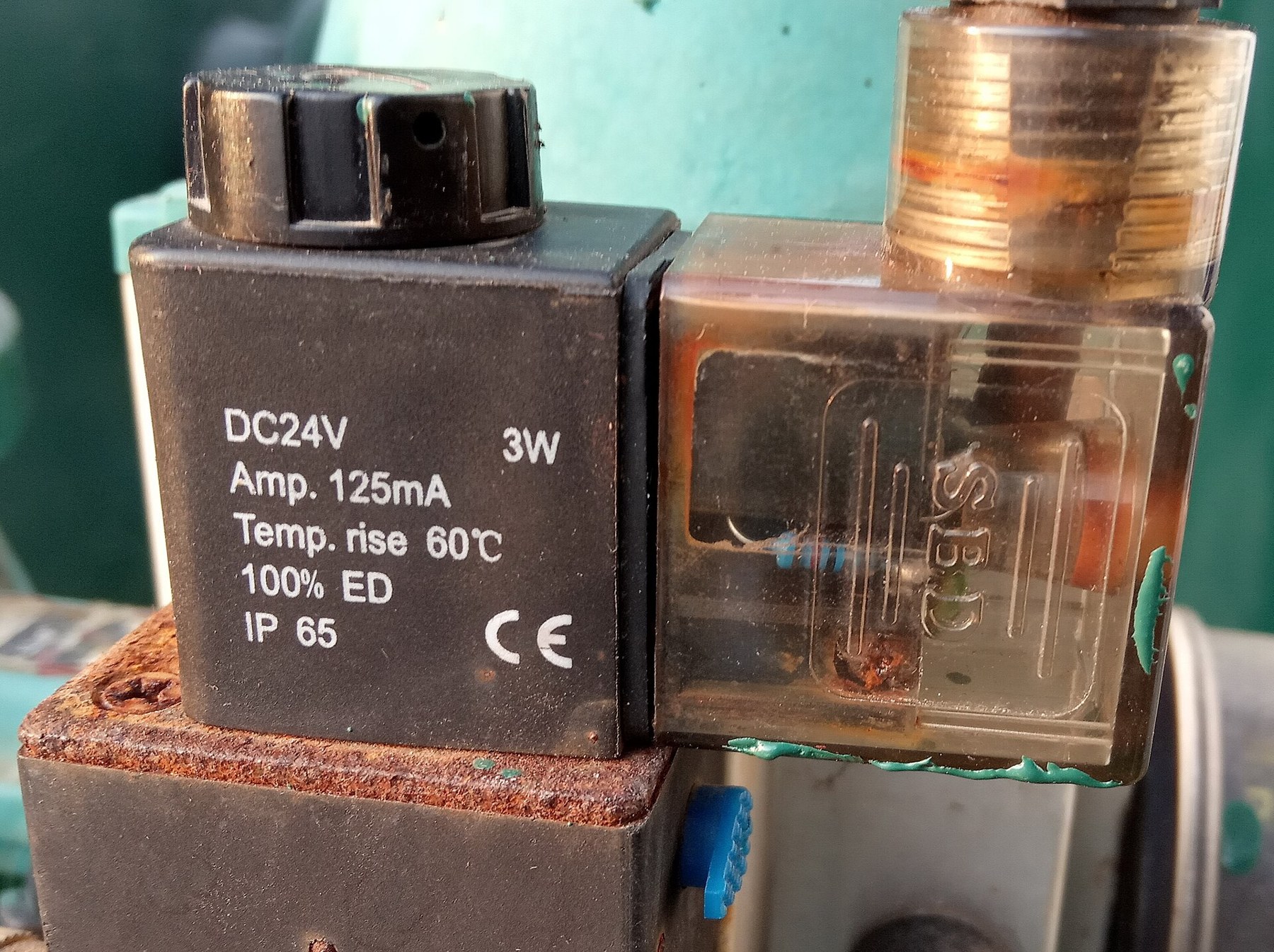
SMC is the example, not a requirement. Festo, Parker, Clippard, Airtac and many others make valves of the same class; what to compare between them is the coil power at 24 V, the response time, the maximum frequency, the shock rating and, above all, the flow figure (C and b to ISO 6358, or Cv), because section 2.4 shows that the flow decides the kick.
2.3 The cylinder: SMC’s CJ2 and CJP
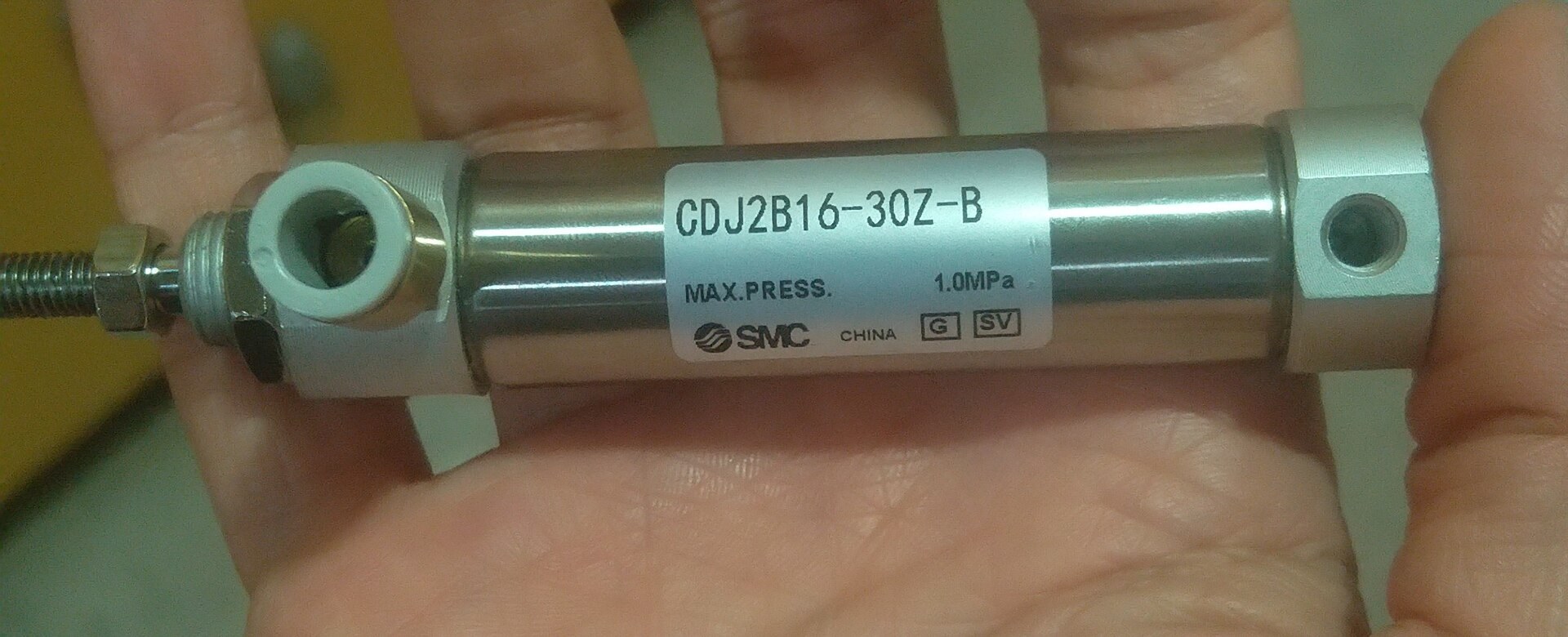
SMC’s CJ2 is a small stainless double-acting cylinder in 6, 10 and 16 mm bores; the CJP “pin” cylinder is a stubbier panel- or plug-mounted part in 6, 10 and 15 mm bores, single- or double-acting.23
Table 2 — The cylinder: SMC's CJ2 and CJP
| CJ2 (double acting) | CJP (double acting) | CJP (single acting, spring return) | |
|---|---|---|---|
| Bores | 6, 10, 16 mm | 6, 10, 15 mm | 6, 10, 15 mm |
| Proof pressure | 1 MPa | 1.05 MPa | 1.05 MPa |
| Maximum operating pressure | 0.7 MPa | 0.7 MPa | 0.7 MPa |
| Minimum operating pressure | 0.12 MPa (ø6), 0.06 MPa (ø10, ø16) | 0.12 MPa (ø6), 0.06 MPa | 0.2 MPa (ø6), 0.15 MPa (ø10, ø15) |
| Piston speed | 50 to 750 mm/s (rubber bumper); 50 to 1000 mm/s (air cushion, ø10 and ø16) | 50 to 500 mm/s | 50 to 500 mm/s |
| Allowable kinetic energy at the end of stroke | 0.012 J (ø6), 0.035 J (ø10), 0.090 J (ø16), rubber bumper; 0.07 J (ø10), 0.18 J (ø16), air cushion | not stated in the pages read | none (no cushion) |
| Lubrication | not required | not required | not required |
The theoretical force at 0.5 MPa is the pressure times the bore area: about 39 N for a 10 mm bore and about 100 N for 16 mm, less seal friction. That is far more than a recoil solenoid manages over a centimetre of stroke (Solenoid Recoil Vol 2), and it does not fall off as the stroke opens, because the force comes from pressure, not from an air gap.
2.4 Why the valve’s flow sets the kick
A cylinder’s force is only there if the valve can keep the pressure up behind a piston that is running away from it. With small valves it cannot. A simple model makes the point: air flowing through the valve according to its ISO 6358 figures (C and b) into the cylinder’s cap end, isothermal, the rod end open to the room, a moving mass accelerating over the full stroke, 3 N of seal friction and 1.5 cm³ of dead volume in the fitting and tube. The model is in this dive’s 04-templates/models.py.
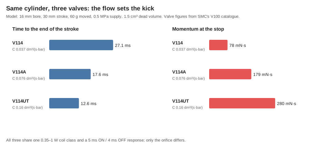
Table 3 — Why the valve's flow sets the kick
| Valve | Cylinder | Moved mass | Time to end of stroke | Speed | Momentum | Energy |
|---|---|---|---|---|---|---|
| V114 | 10 × 15 mm | 30 g | 17.5 ms | 2.4 m/s | 71 mN·s | 85 mJ |
| V114 | 10 × 15 mm | 60 g | 21.2 ms | 2.0 m/s | 117 mN·s | 115 mJ |
| V114A | 10 × 15 mm | 60 g | 15.8 ms | 2.6 m/s | 155 mN·s | 199 mJ |
| V114UT | 10 × 15 mm | 30 g | 9.5 ms | 4.2 m/s | 127 mN·s | 268 mJ |
| V114UT | 10 × 15 mm | 60 g | 11.9 ms | 3.3 m/s | 199 mN·s | 330 mJ |
| V114 | 16 × 30 mm | 60 g | 27.1 ms | 1.3 m/s | 78 mN·s | 51 mJ |
| V114A | 16 × 30 mm | 60 g | 17.6 ms | 3.0 m/s | 179 mN·s | 267 mJ |
| V114UT | 16 × 30 mm | 30 g | 10.3 ms | 5.5 m/s | 166 mN·s | 457 mJ |
| V114UT | 16 × 30 mm | 60 g | 12.6 ms | 4.7 m/s | 280 mN·s | 654 mJ |
Read the table for three things:
- A bigger cylinder on a small valve is worse, not better. The standard V114 cannot fill the 16 mm cylinder fast enough; with a 30 g mass the piston outruns the air and the model delivers almost nothing (2 mJ). The 16 mm cylinder only pays with a large-flow valve.
- The large-flow valve is worth two to three times the momentum of the standard one on the same cylinder, at the same coil power class.
- The times are comparable with a solenoid’s. The Solenoid Recoil model lands its plunger about 10 ms after the pulse starts at 24 V and 24 ms at 12 V (Vol 4). Add the valve’s 5 ms opening time to the table’s figures and an air shot reaches the stop in roughly 15 to 30 ms: in the same band, not faster.
The model ignores the heat of compression, the b-factor’s subtleties at low pressure ratios, the piston’s own mass and any return spring, so its numbers are an order of magnitude to be checked on the bench (Volume 4), not a prediction to design to.
2.5 Cylinder, striker and stop: the rating problem
The catalogue’s allowable kinetic energy is the energy the cylinder’s own bumper can absorb at the end of each stroke without damage: 35 mJ for a 10 mm CJ2 on its rubber bumper, 90 mJ for 16 mm. Every useful row in the table above exceeds it, several times over.
Inside the rating, a cylinder is no better than a solenoid. A 10 mm cylinder held to 35 mJ, moving 20 to 50 g, delivers 37 to 59 mN·s at the stop, the same band as a Ledex B14 with a brass striker (Solenoid Recoil Vol 8). The extra kick pneumatics can give is only available if the impact happens somewhere other than inside the cylinder. Two arrangements do that:
- A free striker. The rod pushes a separate striker that runs on its own guide. The rod stops on its air cushion (or a short external stop on the rod) inside its rating; the striker flies on and hits the gun’s rear stop alone. The kick is the striker’s momentum, set by its mass and the speed it was given. This keeps the cylinder within its rating and is the arrangement to try first.
- An external stop on the rod. A stop on the rod end hits the gun’s structure before the piston reaches its end cover. The cylinder’s internals still decelerate with the rod, so the piston-to-rod joint takes every shot. That is outside the catalogue and a wear question for the bench.
Either way the stop, its damper and its position relative to the stock follow the solenoid rules in Solenoid Recoil Vol 5.
2.6 How much air a shot uses
Free air per shot is the swept volume plus the dead volume, times the absolute pressure in bar:
Table 4 — Free air per shot is the swept volume plus the dead volume, times the absolute pressure in bar
| Cylinder | Swept + dead volume | At 0.3 MPa (4 bar abs) | At 0.5 MPa (6 bar abs) |
|---|---|---|---|
| 10 × 15 mm | 1.2 + 1.5 = 2.7 cm³ | 11 cm³ | 16 cm³ |
| 16 × 30 mm | 6.0 + 1.5 = 7.5 cm³ | 30 cm³ | 45 cm³ |
At a game’s pace of one to three shots a second, the 16 mm cylinder at 0.5 MPa uses about 2.7 to 8 litres a minute of free air; at ten shots a second, 27 litres a minute. The tank covers the bursts. A 1 litre tank held between 0.8 MPa and the regulator’s 0.5 MPa set point gives up about 3 litres of free air before the regulator can no longer hold its setting: about 65 shots of the 16 mm cylinder, or about 190 of the 10 mm one, before the compressor has to catch up. These are own arithmetic from the volumes; the dead volume of a real fitting and tube is a bench measurement.
2.7 The supply: compressor, tank and regulator
A workshop compressor is the simplest supply: it already has a tank, a pressure switch, a relief valve, a gauge and a regulator. Its drawbacks for a living room are its noise when it runs and its size. With a long enough line, it can stay in another room.
A small DC diaphragm pump is the self-contained alternative, and its numbers show its limit. BODENFLO’s BD-04A15L, a 12 V pump sold by Evelta, is rated at 3 bar maximum pressure, 15 litres a minute free flow at zero pressure, no-load current of 0.8 A or less, 305 g, and 63 dB at 30 cm.4 Three bar is 0.3 MPa: enough to run a cylinder at the lower row of the table, not at 0.5 MPa, and its flow falls toward zero as it approaches that pressure. A pump of this class needs a tank and must run between strings of shots. Higher-pressure miniature compressors exist, but no maker’s datasheet for one was read for this volume.
The tank stores the shot air. Any receiver rated well above the compressor’s cut-out, with a drain, will do; a small one is fine because the cylinder uses little.
The regulator is what makes the kick repeatable. With the cylinder pressure held constant, the kick no longer depends on how full the tank is, which is the pneumatic equivalent of the regulated current stage (D13) in the solenoid design: the same shot every time, set by one adjustment. A filter-regulator with a gauge and a manual drain, mounted at the floor end of the line, is the standard part.
2.8 The line to the gun
A light gun on a cable is already tethered (D31: one GX connector at the magazine base plate), so an air line adds a second tether, not a first. A 4 mm outside-diameter polyurethane tube can run in the same braided sleeve as the cable and enter the gun beside it. Points to design for:
- Keep pulls off the fitting. The strain-relief rules for the cable in MP7 Donor Build Vol 2 apply to the tube as well: clamp it to structure, never let the one-touch fitting carry the load.
- Decide where the valve lives. At the gun end, the dead volume is a few centimetres of tube and the kick is crisp; the valve then sees the impact shock (section 2.2). At the floor end, the whole line between valve and cylinder must fill and exhaust on every shot: a 2 m, 2.5 mm bore line holds about 10 cm³, more than the 16 mm cylinder itself, which both slows the shot and doubles the air used. The valve belongs in the gun.
- A quick-disconnect at the gun lets the gun be stored without the line; it must vent the gun side when parted.
2.9 Driving the valve from the carrier
A 24 V valve coil fits the gun’s 24 V rail (D14) directly, and at 15 to 42 mA it is a small load. A logic-level MOSFET switched by a GPIO, with a flyback diode across the coil, is the whole driver: the same class of stage the carrier already uses for its rumble output (Reference Electronics Vol 5). One mismatch needs care: SMC allows its 24 V DC coils ±10 %, 21.6 to 26.4 V (and less for the power-saving types: −7 % to +10 % or −8 % to +10 %), while the gun’s rail is specified at 18 to 28 V working (D14). On a brick that holds 24 V that is no problem; on a sagging or a 6S battery rail it is. Either feed the valve from a 24 V linear or buck stage, or choose a 12 V coil and drop to it. SMC notes that its response times are measured without a surge suppressor; a plain diode slows the valve’s release slightly, which matters little here because the OFF time only governs the return.
What the regulated DRV8251A solenoid stage (D13) does for a solenoid, the pneumatic regulator does for the cylinder. The valve stage needs no current regulation, and the pulse is simply “open long enough for the cylinder to reach the stop”, which the table puts at 10 to 30 ms, plus margin. Holding the valve open longer than that wastes nothing but air and adds nothing to the kick, the same lesson Solenoid Recoil Vol 4 draws for coil heat.
The firmware’s protections change shape. A solenoid that is held on overheats; a valve that is held on simply keeps the cylinder at the stop and hisses on release. The firmware should still cap the on-time, and the D16 rule that the recoil and port outputs never fire together still holds if the port stays a solenoid.
2.10 Noise
Two sources, neither of which a solenoid has:
- The exhaust. Every shot vents the cylinder’s charge, 16 to 45 cm³ of free air in the table above, through port 3 in a few milliseconds. That is a sharp hiss on every shot, inside the gun. A sintered bronze or plastic exhaust silencer on port 3, or a short tube leading the exhaust into a larger volume in the stock, softens it. Its level has not been measured.
- The compressor. The BD-04A15L’s rated 63 dB at 30 cm is in the same range as normal conversation, and it runs whenever the tank needs topping up. A workshop compressor is much louder and is better left in another room.
The impact noise at the stop is the same problem as with a solenoid, and the same damping rules apply (Solenoid Recoil Vol 5).
2.11 Safety with shop air
- Pressure. Everything downstream of the regulator runs below 0.7 MPa, the rating of the valve and cylinder. The regulator must not be able to be set above what the weakest part tolerates, or a relief valve set below that must follow it.
- The tank is a pressure vessel: buy one rated and marked for the purpose, drain it, and never repair or modify it.
- Hose whip and fittings. A one-touch fitting released under pressure throws the tube end; vent before disconnecting.
- Never point an air line at skin, and wear eye protection at the bench.
- Never use oxygen, and never let oil into a high-pressure fill; paintball’s warning about lubricant in an HPA tank’s fill nipple, which can ignite under compression, applies to any high-pressure source (Volume 3).
2.12 Keeping it working: maintenance and repair
Table 5 — Keeping it working: maintenance and repair
| Item | What to do | Source |
|---|---|---|
| Filter-regulator bowl | Drain the condensate; replace the element when the pressure drop rises | Standard practice for any compressed-air line |
| Tank | Drain after each session; inspect for corrosion; replace, never repair | Standard practice |
| Valve and cylinder lubrication | None needed; SMC states both are non-lube | SMC catalogues12 |
| Cylinder bumper or cushion | Inspect for wear; the striker arrangement (section 2.5) is meant to keep the cylinder within its rating | SMC CJ2 allowable kinetic energy |
| Rod seal | A leak at the rod shows as hissing between shots and a weaker kick; replace the cylinder (small CJ2 and CJP are usually sold complete) | — |
| Valve | A valve that buzzes or leaks to exhaust at rest has dirt on its seat; filter the supply | — |
| Line | Inspect for kinks and abrasion where it enters the gun | — |
Fault finding. No kick and no hiss: no air (check the gauge) or no coil drive (check the coil current on the scope). Hiss at the exhaust but no kick: the cylinder is not filling (a kink, a too-small valve, or the line rather than the cylinder being filled because the valve is at the floor end). A kick that weakens through a string: the tank is falling below the regulator’s set point; the compressor or the tank is too small.
2.13 Why this, and why not the others
Table 6 — Why this, and why not the others
| Choice | Picked | Rejected, and why |
|---|---|---|
| Valve class | Direct-operated 3/2 N.C., 24 V coil, large-flow type (SMC V114UT or V114A class) | Standard V114: a third to half the momentum on the same cylinder (section 2.4). Pilot-operated valves: need a minimum pilot pressure and are slower; no advantage at this size. 5/2 valves: only needed for a double-acting return, which a spring does more simply |
| Cylinder | 10 mm bore, 15 mm stroke, with a free striker | 16 mm: more momentum only with the large-flow valve, and twice the air per shot. 6 mm: 12 mJ bumper rating and little force |
| Return | Single-acting spring return, or the striker’s own spring | Double-acting: a second valve or a 5/2 valve and twice the exhaust noise |
| Valve location | In the gun, close to the cylinder | At the floor: the line volume doubles the air used and slows the shot |
| Supply | Workshop compressor in another room, filter-regulator at the floor end | 12 V diaphragm pump: 3 bar only and runs in the room; bottled HPA or CO₂: covered in Volume 3 |
| Driver | GPIO → logic-level MOSFET, flyback diode, 24 V rail | The DRV8251A regulated stage: unnecessary at 15–42 mA |
These are proposals for a bench experiment, not a design for the first gun: see the verdict in Volume 4.
2.14 What could not be verified
- Prices. SMC sells through distributors at quotation; no dated price for a V114, V114A, V114UT, CJ2 or CJP was found on a maker or major distributor page on 19 October 2026.
- Model results. Every speed, time and momentum in section 2.4 is from an isothermal model with assumed dead volume and friction.
- The CJP’s allowable kinetic energy was not in the pages read.
- Exhaust noise level. Not measured; no published figure found for a valve venting a small cylinder.
- A higher-pressure miniature compressor with a maker’s datasheet was not found.
Sources
Footnotes
-
SMC, Direct Operated 3-Port Solenoid Valve, V100 Series (catalogue), https://content2.smcetech.com/pdf/V100.pdf, read 2026-10-19 (specifications, solenoid specifications, flow-rate characteristics, weights). ↩ ↩2
-
SMC, Air Cylinder: Standard Type, Double Acting, Single Rod, CJ2 Series (catalogue), https://content2.smcetech.com/pdf/CJ2.pdf, read 2026-10-19 (specifications: proof and operating pressures, piston speed, allowable kinetic energy). ↩ ↩2
-
SMC, Pin Cylinder, CJP Series (catalogue), https://content2.smcetech.com/pdf/CJP.pdf, read 2026-10-19 (specifications, double acting and single acting spring return). ↩
-
Evelta, “12V Micro Diaphragm Air Pump for Beauty Machines Max Flow 15L/min” (BODENFLO BD-04A15L), https://evelta.com/12v-micro-diaphragm-air-pump-for-beauty-machines-max-flow-15l-min/, read 2026-10-19; ₹2,665.48 including GST on that date. ↩
Comments (0)