MP7 Light Gun: Donor Build · Volume 2
The Donor Inside — Layout, Volumes and What Has to Come Out
What public photographs, retailer descriptions and owners' teardowns show of the inside of the gas and electric airsoft MP7s; the two ejection-port concepts to try in each of the three donors; the cable out through the magazine base plate; where a Pico carrier fits; what must be removed; and the measurements to take when the donors are opened
2.1 What this volume can and cannot say
No donor has been opened. Everything here comes from public sources: the makers’ product photographs, retailer descriptions, two owners’ teardowns of Tokyo Marui guns (one Japanese magazine article and one French club blog), and parts listings. No exploded diagram for any airsoft MP7 was found online; the retailers say each gun ships with a manual, so the first thing to do when the donor arrives is to photograph that manual. The volume is therefore a plan to be checked, and every section ends in what has to be measured. Where the real teardown proves it wrong, it gets rewritten.
Volume 1 ends with three donors bought for comparison: the KWA-made Elite Force gas gun, the VFC-made Gen 3 electric, and the Elite Force / Umarex spring gun as a practice shell. This volume sets out, for each, the concepts the comparison will test. The public teardown material is almost all for the Tokyo Marui guns, which share the outline but not necessarily a single internal part with either. Read the Tokyo Marui details below as the shape of the problem, not a parts map of the KWA or VFC.
2.2 The shape everything has to fit
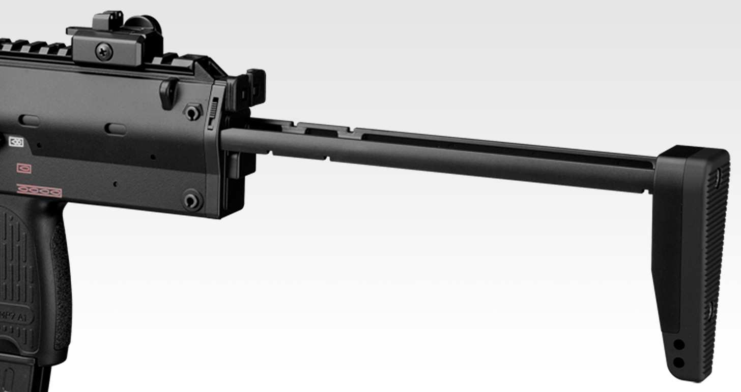
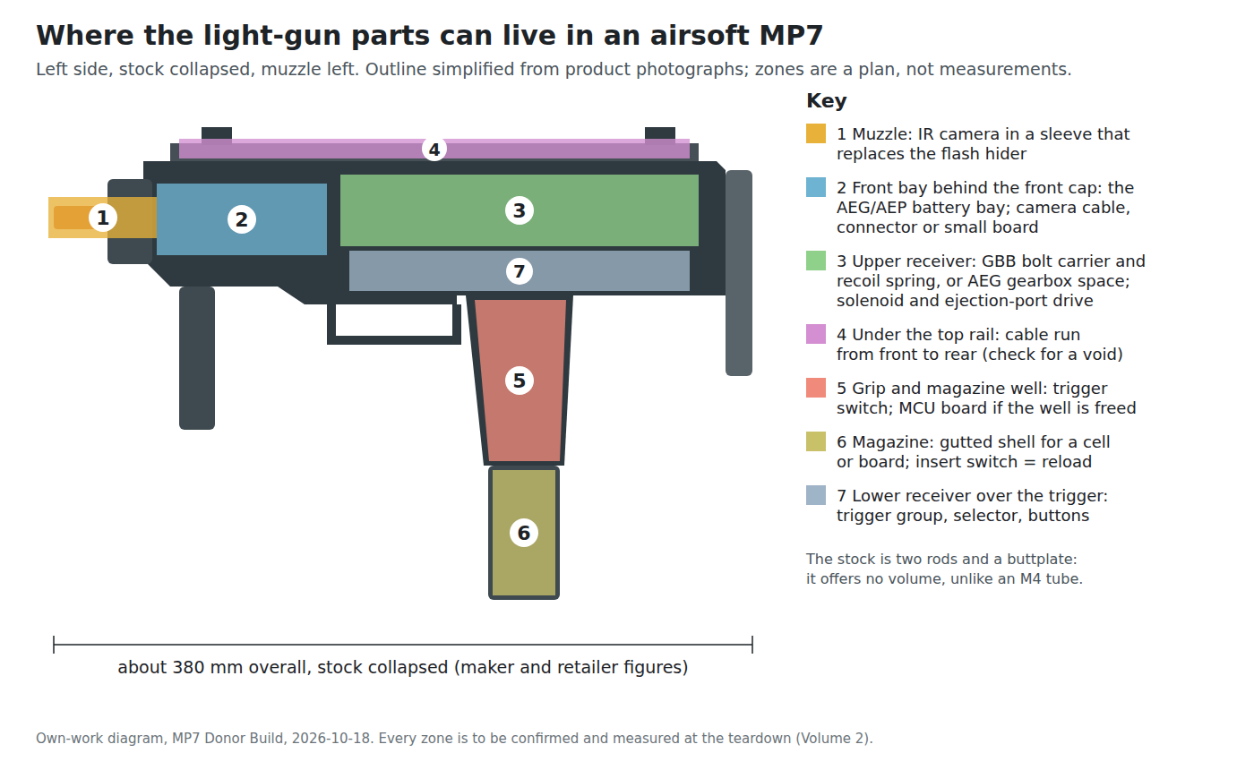
Every airsoft MP7 follows the real gun’s layout (the HK MP7 dive owns the real one): a tall, short receiver with a full-length top rail; a front cap carrying the muzzle and side rails; a pistol grip with the magazine running up through it, so the magazine well is the grip; a folding foregrip under the front; and a stock of two rods and a buttplate that slides forward along the receiver sides. Overall it is about 380 mm long with the stock in, by every maker and retailer that publishes the figure.
Two consequences follow before any part is unscrewed:
- The stock offers no volume. On an M4-pattern donor the buffer tube is the classic place for a battery. On an MP7 the stock is two rods. Everything has to live in the receiver, the front bay, the grip and the magazine.
- The magazine well takes the middle of the grip. Whatever goes in the grip has to share it with the magazine, or replace the magazine’s contents.
2.3 Inside the gas guns
What public sources establish about the gas-blowback (GBB) MP7s, from Tokyo Marui’s page, retailer descriptions and the French Tokyo Marui teardown:
- The gas lives in the magazine. Tokyo Marui’s is die-cast; the magazine holds the propellant, the BBs and the valve that releases a shot’s worth of gas.1 (The Airsoft Gas dive covers how GBB magazines and gases work.)
- The bolt carrier carries a nozzle and blows back on its own spring. Tokyo Marui describes “a new blowback engine” with a large piston of about 16 mm diameter, the bolt cycling with each shot.1 The French teardown describes a spring-loaded nozzle head and nozzle guide, a “blowback valve”, a buffer with its own recoil spring, and a hammer with a steel roller.2
- It comes apart at a rear takedown pin. In the Tokyo Marui gun, pushing the rear pin lets the trigger group separate from the receiver; pressing the buffer releases the buffer and recoil spring.2 Whether the KWA and VFC guns open the same way is unconfirmed.
- The action housing on the KWA gun is metal. Airsoft Station describes a “full metal action housing” inside a fibre-reinforced polymer outer body.3 That is the part that guides the bolt carrier, and it is the part a solenoid would bolt to.
- The hop-up adjuster is reached through the receiver. Tokyo Marui says the dial becomes accessible when the bolt is held back.1
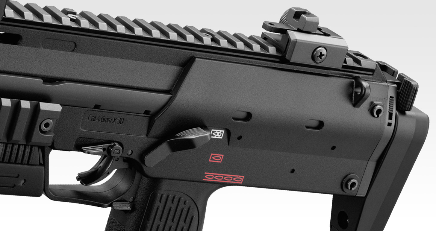
What this means for the build. The gas gun’s moving parts are the ones the brief asks for: a carrier that runs back and forward behind the ejection port, guided by a metal housing, returned by a spring and stopped by a buffer. Everything that makes it fire — the magazine valve, the nozzle, the hammer and knocker, the inner barrel and hop-up — is surplus.
2.4 Inside the electric guns
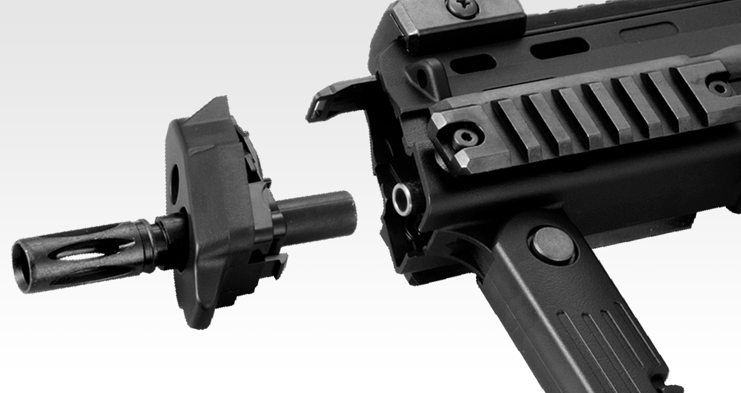
The front bay. On the VFC electric, the battery sits in the front of the receiver above the barrel, behind a front cap that pops off; reviewers call it tight and recommend a short buffer-tube-style 11.1 V 900 mAh LiPo.4 (One retailer puts it in the stock, which the stock’s construction rules out; see Volume 1.) Tokyo Marui’s own product photograph of its electric gun shows the front cap and flash hider coming away as one assembly, and an owner’s photographs show the same front cap off with the inner barrel exposed, alongside the 7.2 V micro battery and a LiPo adapter.56
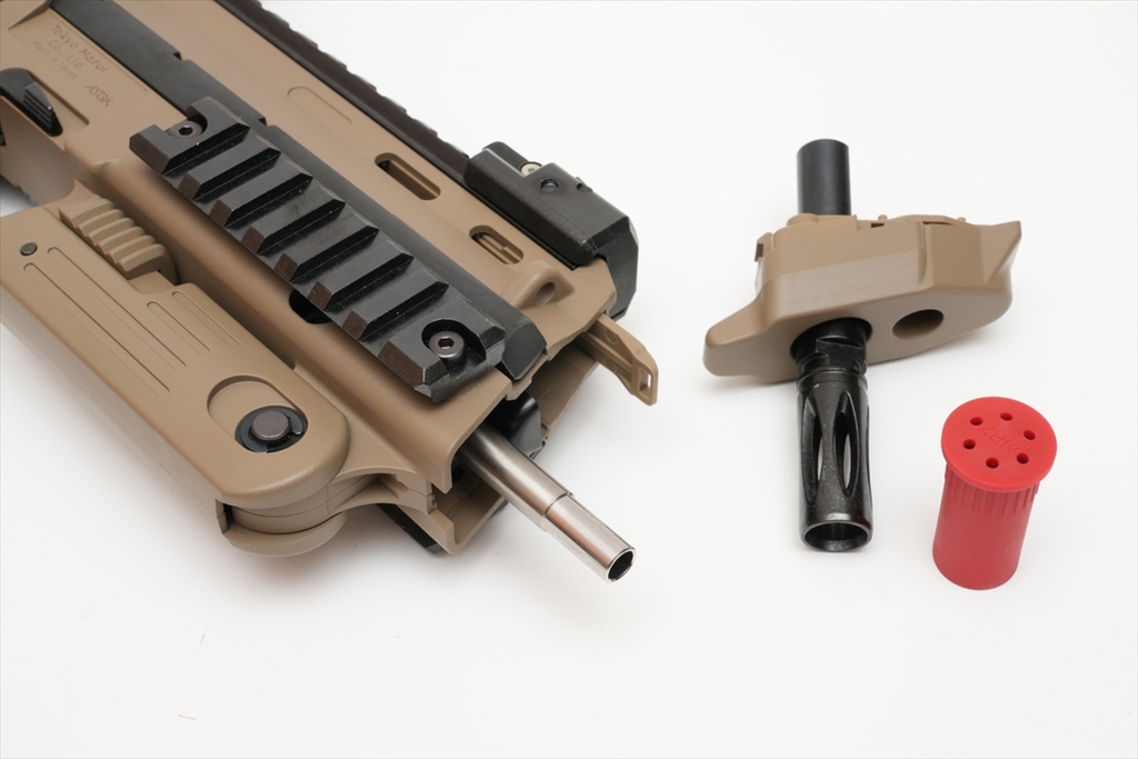
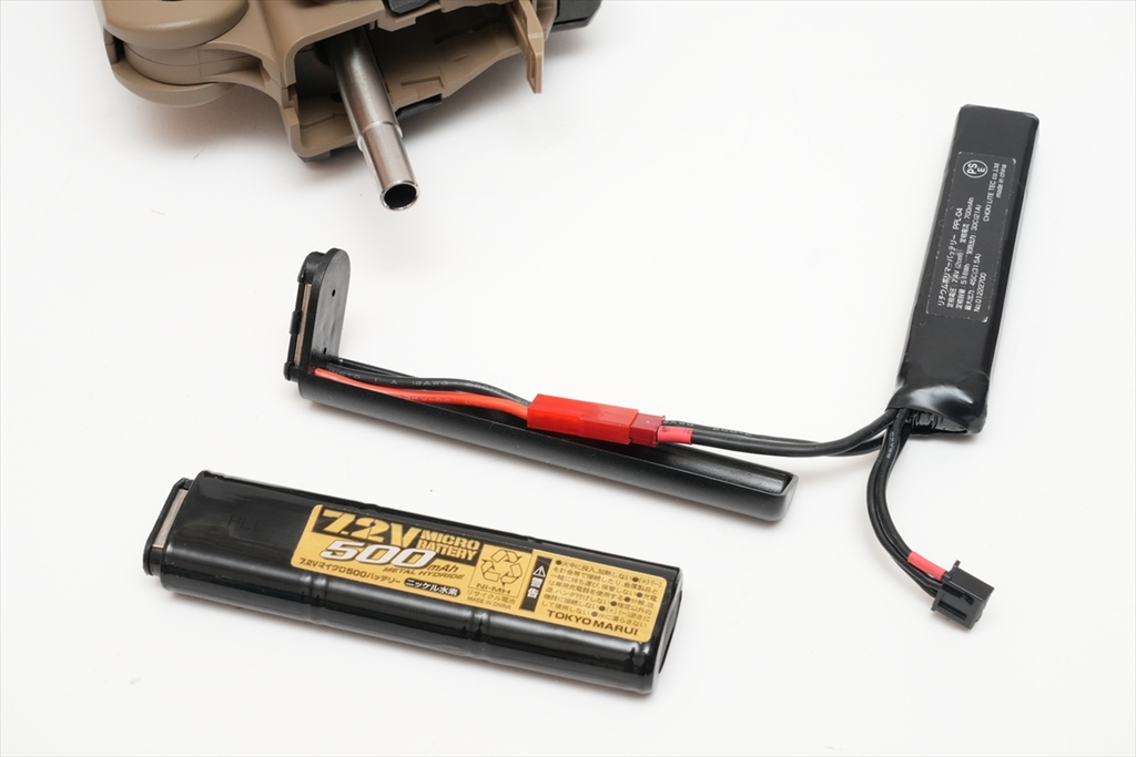
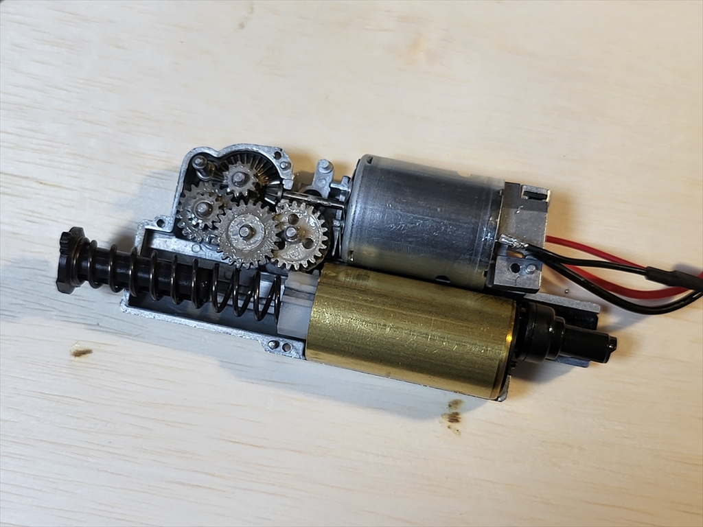
The mechbox. The Tokyo Marui electric uses a compact mechbox in which the motor lies alongside the cylinder rather than in the grip, as an owner’s photograph shows. That owner needed about six hours to replace the spring and close the box again because springs flew out and parts scattered when it was opened, and bought a complete spare mechbox assembly.6 The French teardown gives a removal order for the Tokyo Marui electric: unscrew the top rail; disconnect the motor’s two leads; remove the fuse; remove the stock; remove the two pins at the rear; unscrew the hop-up linkage; slide the mechbox out.7 For a conversion, the important word is out: the mechbox leaves as a unit and is never reassembled.
The VFC electric has a built-in MOSFET, a quick-change spring and what one retailer calls a “Version 2 VFC Avalon gearbox”; VFC’s parts listings warn that the gearbox has to be disassembled to change the piston and recommend professional installation.89 No photograph of its gearbox out of the gun was found.
What this means for the build. The electric gun’s gift is the front bay and the wiring path from it to the receiver: a wire already has to run from the battery at the front to the motor in the middle. It gives nothing that moves.
2.5 The camera at the muzzle
The camera has to look down the bore line from the front of the gun. The obvious mount — behind the flash hider, looking out through it — does not work, for plain geometry.
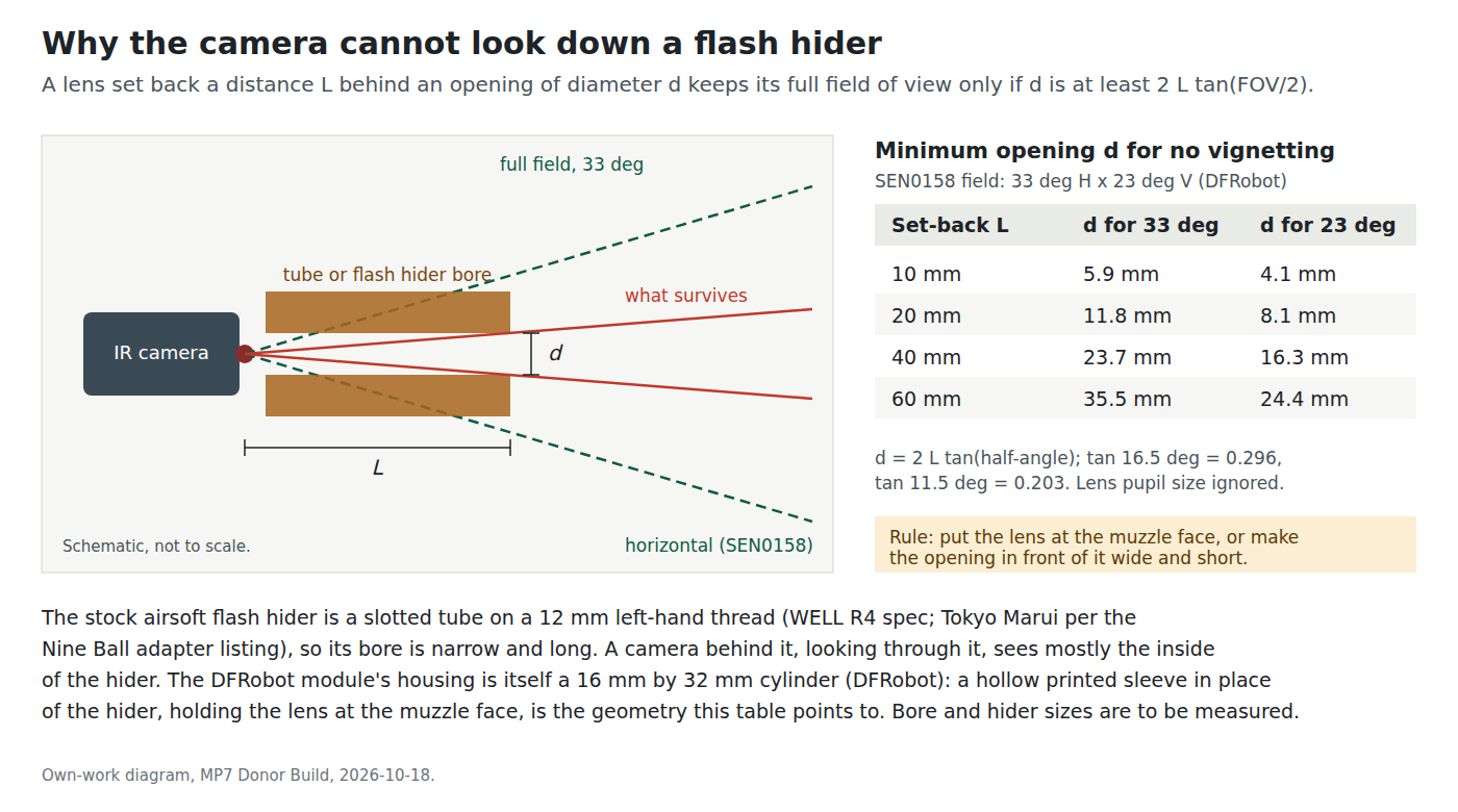
The DFRobot SEN0158’s field is 33° horizontal by 23° vertical, by DFRobot’s figures.10 For a lens set back a distance L behind an opening of diameter d, the opening must satisfy d ≥ 2 L tan(16.5°) ≈ 0.59 L horizontally and d ≥ 0.41 L vertically, ignoring the lens’s own aperture. An airsoft flash hider is a slotted tube on a 12 mm left-hand thread (WELL’s specification for the R4; Tokyo Marui’s thread, per Nine Ball’s adapter, is the same 12 mm CCW), so its bore is perhaps a centimetre and its length several centimetres.1112 Behind it, the camera sees the inside of the flash hider.
Losing field of view matters more than it sounds: the field of view sets how close to the screen the player can stand before the LEDs at the screen edges leave the camera’s view. The Open-Source Firmware dive and the planned aiming-maths dive own that relationship.
The workable layouts, in order of preference:
- A camera sleeve in place of the flash hider. The SEN0158’s housing is itself a threaded cylinder 16 mm in diameter and 32 mm long. A printed (or, later, turned) sleeve the shape of the MP7’s flash hider that holds the camera with its lens at the muzzle face puts the lens where it must be and keeps the outline. Its outside diameter depends on the camera; whether that still reads as an MP7 muzzle is a question for the printer, not the calculator. The cable runs back through where the outer barrel was: on the electric donor alongside the battery leads from the front bay, on the gas donor beside the space the inner and outer barrel leave, or under the top rail if it sits over a void (zone 4 in the zones figure, to be checked).
- The bare sensor on a small board in a hollow hider. The camera module’s electronics do not have to live in the DFRobot housing. A small board carrying only the sensor and its lens, in a slimmer sleeve, is a job for the Reference Electronics dive and its Altium layout.
- A short, wide opening. If the camera has to sit behind something, that something must be wide and short, per the table in the figure.
There is a legal wrinkle here too: the orange marking an imitation firearm needs is usually at the muzzle, exactly where the camera wants to be. Volume 3 shows that the marking rules allow an orange band on the outside of the barrel, which leaves the bore clear.
2.6 Kick and the moving ejection port
The brief is kick only, plus a moving ejection port. Decision (D5, 18 October 2026): try both of the ways that can be done, and choose on feel and reliability. Concept A uses one solenoid for the kick and the port. Concept B uses a kick solenoid and a separate actuator for the port. Both are proposals to be tested in each donor; neither has been built.
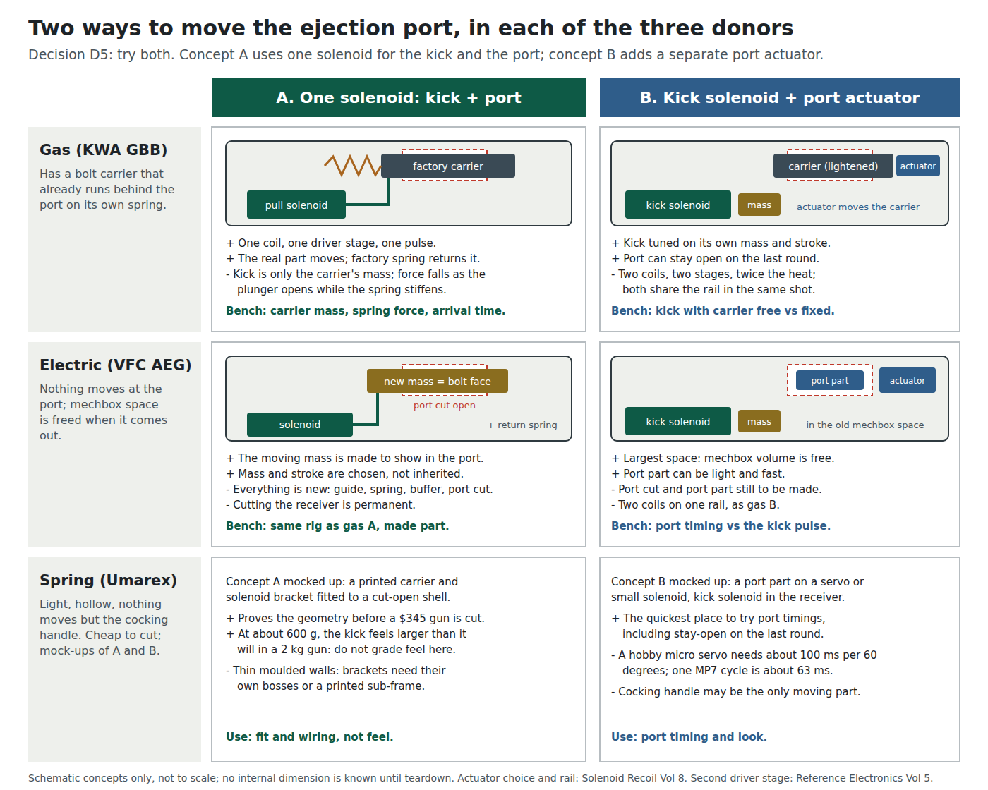
2.6.1 Concept A: one solenoid for kick and port
Gas donor. Do with a solenoid what the gas did. A pull solenoid linked to the factory carrier draws it back over some stroke; the factory recoil spring returns it; the buffer stops it. The carrier is visible in the ejection port throughout, so the port “moves” because the real part behind it moves. The alternative layout is a push solenoid striking the carrier from the front, as many light guns hit a slide.
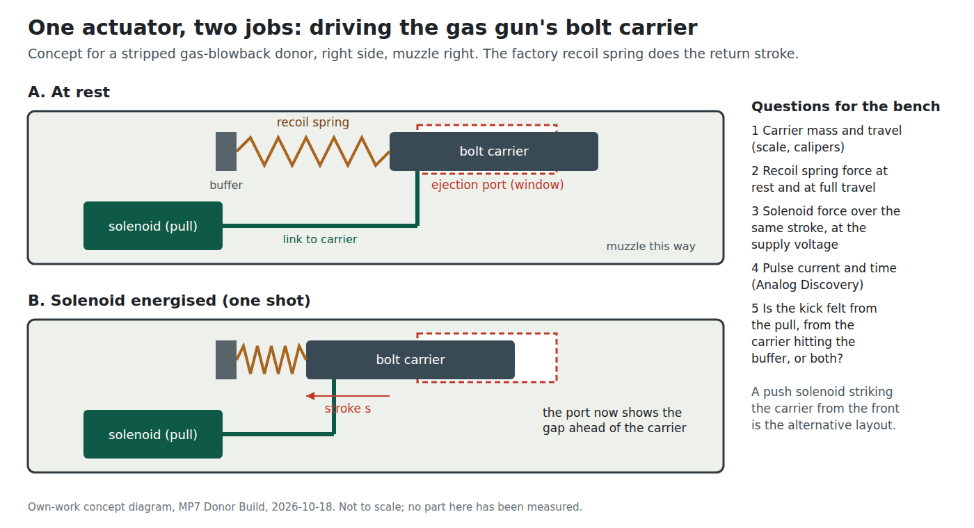
Whether this works is a matter of numbers no public source gives: the carrier’s mass and travel, the recoil spring’s force over that travel, and the force a solenoid that fits can produce over the same stroke. A solenoid’s force falls steeply as its plunger opens, which is the wrong direction for a spring that stiffens as it compresses. Two consequences follow from the Solenoid Recoil dive’s Volume 8. The kick of concept A is the carrier’s momentum, and momentum at a fixed energy grows as the square root of the moving mass, so a light carrier gives a light kick however fast it moves. And the stroke is set by the carrier, not chosen for the solenoid.
Electric donor. There is no carrier. The solenoid drives a new moving mass, shaped so that its face shows through a port cut in the receiver, on a made guide with its own return spring and buffer. Everything is made, so mass and stroke are chosen rather than inherited; the cost is that every part of it, including the opening in the receiver, has to be designed and cut.
Spring shell. The concept is mocked up: a printed carrier and a solenoid bracket in a shell cut open to see inside. It proves the geometry and the wiring, not the feel. At 600 g the shell is about a third of the weight of the gas gun, so the same impulse gives it roughly three times the recoil velocity; a kick that feels right in the spring shell will feel weak in the finished gun.
2.6.2 Concept B: a kick solenoid and a separate port actuator
The kick solenoid drives its own mass, chosen for the kick alone, in the space the internals leave: where the gas parts were, or in the mechbox space of the electric gun. A second, smaller actuator moves only the part in the port: the factory carrier, lightened, in the gas gun; a made port part in the electric gun.
What it gains: each actuator does one job, so the kick mass and stroke can be chosen freely, and the port can behave unlike the kick, for example staying open on the last round as a real bolt does. What it costs: two coils, two driver stages, twice the heat, and a short delay between the kick and the port, because the two stages never fire at the same instant (decision D16).
2.6.3 The port actuator: why this, and why not the others
Concept B needs a port actuator. The Moving Ejection Port dive owns the final choice; this is the shortlist to try in the donors. The criteria are: complete a port stroke within one shot at the real gun’s rate (about 950 rounds a minute, so about 63 ms a cycle, by a figure H&K is reported to give for the MP7A2);13 fit beside the kick solenoid; run from the board’s existing outputs.
Table 1 — The port actuator: why this, and why not the others
| Candidate | Status | Why, and why not |
|---|---|---|
| A second, small solenoid, from the 6–12 V class on the Solenoid Recoil Vol 8 shortlist | Proposed, to test first | Arrives in milliseconds; runs on the same 24 V regulated rail and an identical second driver stage the reference board already carries (Reference Electronics Vol 5 §5.11); can follow the kick on the same command with stock firmware. Costs a second coil’s heat and current. |
| A hobby micro servo (TowerPro SG92R, Adafruit 169, $5.95 on 18 Oct 2026) | For slow events only | Adafruit gives “0.1 sec/60 degrees (at 4.8V)”, 2.5 kg-cm, 23 × 11 × 29 mm and 9 g.14 A 60° swing takes about 100 ms, longer than one 63 ms cycle, so it cannot follow automatic fire. It can hold the port open on the last round or on a reload, from a pulse-width signal on the fork’s spare pin, with no power stage. |
| A small geared motor turning a cam | Rejected for the first test | Could cycle continuously in step with automatic fire, but needs position sensing to stop in the right place, adds gear noise, and is a new driver class on the board. |
| A linkage from the kick solenoid | That is concept A | Listed so it is not mistaken for a third option. |
2.6.4 The electrical side
Both concepts run on the rail the Solenoid Recoil dive proposes: 24 V nominal (18–28 V working), current regulated, the coil chosen from the “6–12 V” class, with the pulse ended at landing (Solenoid Recoil Vol 8). That volume’s bench shortlist (Ledex B14-255-B-1, Guardian TP6x12-I-12, Adafruit 413, and the JF-0530B and JF-0826B marketplace parts) is the set of kick solenoids to try in each donor; it is not repeated here. What the donor adds to that choice is a size limit and a moving mass: candidates are compared at the mass the donor will move (the carrier in concept A), not at their bare plungers.
The reference board carries a second, identical solenoid stage for concept B, on its own command pin from the project’s fork, which is also what a last-round hold-open needs (Reference Electronics Vol 5). The two stages never fire at the same instant (decision D16): the firmware sequences them, so the fuse, the supply and the bulk capacitor are sized for one stage (Power Supplies). The port follows the kick by about 16 ms, which Moving Ejection Port, Volume 2 shows is below the delay at which sight and touch are felt to be out of step. (Corrected 2026-10-19: this paragraph earlier had the two coils firing together and a jumper to run them in parallel.)
2.6.5 How the two concepts are compared on the bench
The rig is the one Solenoid Recoil Vol 6 describes, with the donor in place of the test mass. The instrument is the lab’s Digilent Analog Discovery Pro ADP3450: four single-ended analogue channels (14-bit, at least 55 MHz, up to 125 MS/s), 16 digital I/O and a stand-alone Linux mode, per Digilent’s specification as read for that volume. It has no current input, so coil current is captured as the voltage across a low-side shunt (the reference board’s 10 mΩ R_S, 10 mV per amp) on a ground-referenced channel; a clamp-on current probe with a BNC output is the alternative where the circuit cannot be broken. The drain node exceeds the ±25 V input range and is probed ×10.
Table 2 — How the two concepts are compared on the bench
| ADP3450 channel | Concept A | Concept B |
|---|---|---|
| 1 | Kick coil current (shunt) | Kick coil current (shunt) |
| 2 | Rail voltage at the board | Port coil current (second shunt) |
| 3 | Carrier at end of travel (slotted optical switch across the port) | Port part at end of travel (same sensor) |
| 4 | Accelerometer on the receiver, if fitted | Rail voltage at the board |
| Digital | Trigger and the firmware’s solenoid command | Trigger, both commands |
The programmable supplies step the rail across 18–28 V and set the current limit, the USB-controlled units from a script so every shot is logged against its rail voltage; the Bluetooth-controlled unit is the second rail when the port actuator is a servo on 5 V. Per shot, the numbers kept are: arrival time at end of travel, peak and regulated current, energy from the supply, coil temperature after a 30-shot burst, and Michael’s verdict on the feel. Concept A passes if the carrier reaches the end of its travel inside one cycle on the 24 V rail without exceeding the coil’s pulse rating; concept B passes if the port completes its stroke inside the same shot and the combined heat stays inside both coils’ ratings.
2.7 The cable exit through the base plate
Decision (D6, 18 October 2026): the cable leaves through the bottom of the magazine base plate, for now. It keeps the grip, the stock and the receiver uncut, and is revisited for the printed build.
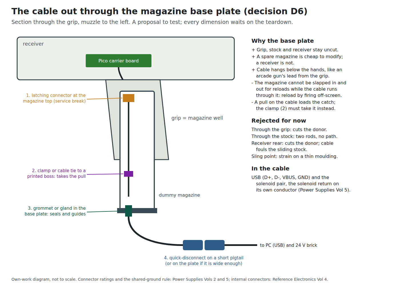
2.7.1 What runs in the cable
USB (D+, D−, VBUS, ground) to the PC, and the solenoid supply pair from a 24 V brick, with the solenoid’s return on its own conductor rather than shared with the USB ground (Power Supplies Vol 5). The reference design asks for 22 AWG twisted pair for the solenoid, OpenFIRE’s floor being 24 AWG, and 26–28 AWG for signals (Reference Electronics Vol 9). Concept B with a second coil adds no conductors: both stages share the rail.
2.7.2 The route in each donor
Table 3 — The route in each donor
| Donor | From board to magazine | Inside the magazine | Notes |
|---|---|---|---|
| KWA gas | Down through the top of the magazine well, where the gas nozzle met the magazine’s valve | The factory magazine is the gas tank itself (an owner describes it as “a gas tank with two pressure valves, a firing cap to release the gas and a locking follower”)15 | Decision (D21, 18 October 2026): buy a spare KWA gas magazine to machine; never cut the original. The spare is Umarex/Elite Force 2279021, “Only for use with the KWA HK MP7 Gas Blowback Airsoft gun”, $74.99 at Umarex USA and Airsoft GI on 18 Oct 2026.16 It is machined only after it has been emptied of gas (Volume 3). A printed dummy body remains the fallback if the spare’s internals leave no room. |
| VFC electric | Down through the top of the well, which opens into the receiver once the mechbox is out | A polymer shell around a BB feed: the follower, spring and feed come out | The earlier VFC electrics detect an empty magazine (the Gen 3 page does not say); whether any part of that is in the magazine or the well is a teardown question. |
| Spring shell | The same | Plastic; cut freely | Where the route, the clamp and the gland are tried first. |
2.7.3 Strain relief
The cable will be pulled, stepped on and swung. The rule is that no pull may reach the magazine catch or a solder joint. In order from the outside: a short pigtail so the quick-disconnect hangs clear of the hand; a grommet or cable gland in the base plate that guides the cable and seals the hole; a clamp or cable tie to a boss printed inside the magazine, which takes the load; a service loop above the clamp; and a latching connector at the top of the magazine (JST PH for signals and VH for the solenoid pair, the families the reference board uses, Reference Electronics Vol 4 §4.8) so the magazine can be pulled for service without cutting anything. While the cable runs through it, the magazine stays seated in play; reloads come from the usual off-screen trigger pull instead.
2.7.4 The quick-disconnect: why this, and why not the others
Decision (D22, 18 October 2026): a GX12 or GX16 inline connector is acceptable to start, mated only with the power off, because it is cheap, robust and available. A hot-pluggable connector is a question for the finished gun, not the bench.
Decision (D31, 19 October 2026): the GX is the one connector at the gun, carrying USB and the 24 V rail together, with no barrel jack beside it (Power Supplies Vol 6). The order of use makes up for the lack of hot-plugging: the GX is mated before the brick goes into the wall, and the brick comes out of the wall before the ring is turned. The solenoid return has its own pin, apart from USB ground.
The criteria: a positive lock; ratings with margin for the solenoid pulse; no chance of 24 V reaching a logic pin while mating; small enough for a magazine base plate whose width is not yet known; and cheap to replace.
Table 4 — The quick-disconnect: why this, and why not the others
| Candidate | Status | Why, and why not |
|---|---|---|
| Inline circular connector on a short pigtail (GX12 or GX16 cable plug and socket) | Decided (D22, 18 October 2026) for the bench, unpowered mating only; revisited for the finished gun | Locks with a screw ring; multi-pin, so USB and the solenoid pair go in one plug, as the Blamcon Vyper does with a GX16;17 needs no panel space on the base plate. GX12 is the one with a maker datasheet (Olimex, 5 A); GX16 ratings are only sellers’ (5–20 A, inconsistent; Fully Wired, Volume 3). Not hot-pluggable: while the ring turns, pins can touch the wrong sockets, so power is off before mating and the pins are allocated so a one-position slip cannot put 24 V on a data line (Power Supplies Vol 2). |
| The same connector panel-mounted in the base plate | If the plate is wide enough | Neater, and the gland goes away; a GX12 needs a 12 mm hole and a GX16 about 16 mm, both by sellers’ listings. Decided by the base plate’s measured width. |
| USB-C panel extension in the base plate, plus a separate 24 V lead | Rejected | Adafruit’s small round USB-C panel extension (product 6069, $4.50 on 18 Oct 2026) needs a 12–18 mm hole; its larger one (4218, $9.95) needs 21.5–27 mm.1819 Either way the solenoid supply needs a second connector and a second cable. |
| Magnetic breakaway (Adafruit 5358, four 0.1 in pogo pins, $6.50) | Rejected for the solenoid; kept in mind for a USB-only gun | Its appeal is that a yanked cable lets go instead of dragging the gun off a table, and reversed halves repel.20 But Adafruit’s page gives no current rating (one reseller lists 2 A / 36 V, unconfirmed), and a solenoid pulse through 0.1 in pogo pins is not a load to trust without one. |
| A bare USB cable plus a barrel jack, no quick-disconnect | Rejected | Two cables from the base plate, and a barrel jack carries no voltage keying (Power Supplies Vol 2). |
2.7.5 Exits rejected for now
Table 5 — Exits rejected for now
| Exit | Why not |
|---|---|
| Through the pistol grip | Cuts the donor where the hand is; the grip is the magazine well, so there is little wall to cut. |
| Through the stock | Two rods and a buttplate: no path, and the stock slides. |
| Rear of the receiver | Cuts the donor, and a cable there fouls the stock as it slides along the receiver. |
| Sling point | Puts the cable’s load on a thin moulding not designed for it. |
| Muzzle | The camera is there (§2.5). |
The Reference Electronics floorplan gathers the cable at the stock end of the carrier. Under this decision the cable enters from below, over the grip, so the carrier’s cable connector belongs on the edge that faces the magazine well.
2.8 The board: a Pico on a carrier
Decision (D7, 18 October 2026): a Raspberry Pi Pico on a carrier board to start, with a custom PCB designed in Altium later. The board, its pin budget and the reasons for the Pico over the alternatives are the Reference Electronics dive’s; this section sizes the space it needs in each donor.
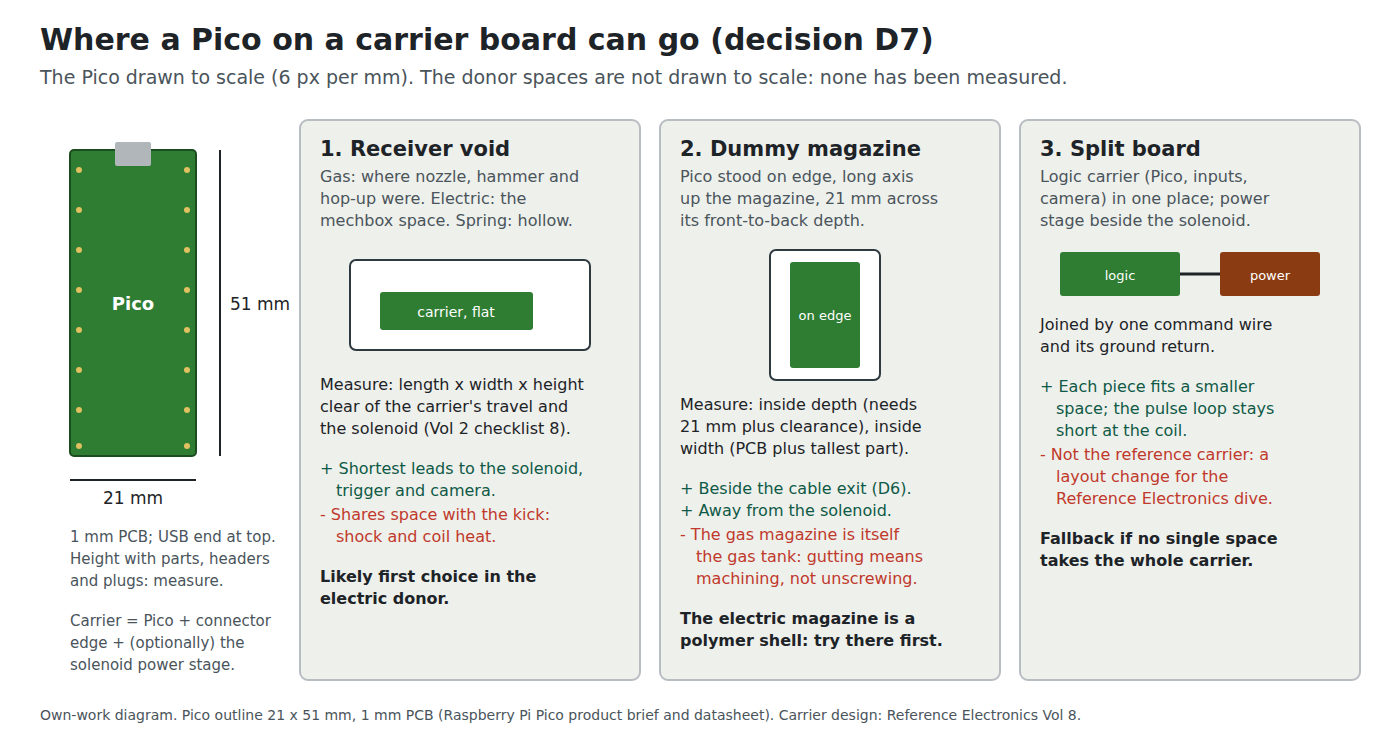
The Pico is 21 × 51 mm on a 1 mm PCB, by Raspberry Pi’s product brief and datasheet.21 Its height with components, the micro-USB socket and any headers is not given in the text of either and should be measured; on a carrier, the connectors add height and one edge’s worth of width. The carrier’s outline waits on the donors: the floorplan in Reference Electronics Vol 8 is drawn for “an MP7-size receiver” with illustrative proportions, and the measurements below set its ceiling.
Table 6 — The board: a Pico on a carrier
| Donor | Receiver void | Dummy magazine | Front of the gun | First place to try |
|---|---|---|---|---|
| KWA gas | Where the nozzle, hammer, valve knocker and hop-up were, beside the carrier’s travel | Only in a machined spare or a printed body | No bay; outer barrel space only | Receiver, clear of the carrier |
| VFC electric | The mechbox space, the largest in any donor | Polymer shell; on edge if the inside depth clears 21 mm | Battery bay: kept for the camera cable, later the battery | Receiver |
| Spring shell | Hollow | Hollow | Hollow | All three, as mock-ups |
On edge in the magazine. A magazine is narrow side to side and deeper front to back. Stood on edge with its long axis up the magazine, the Pico needs an inside depth of 21 mm plus clearance and an inside width of its PCB plus the tallest part on it. If the magazine clears that, the board sits beside the cable exit and away from the solenoid’s shock and heat; if not, the magazine carries only the connector and strain relief.
Split board. If no single space takes the whole carrier, the logic (Pico, inputs, camera connector) goes in one place and the solenoid power stage beside the coil, joined by the command line and its ground return. That keeps the pulse loop short at the coil, but it is a layout change for the Reference Electronics dive, not the reference carrier.
If space wins. The Reference Electronics dive lists smaller RP2040 boards, such as Adafruit’s KB2040 at 35.0 × 17.8 mm, with partial pin support in OpenFIRE; that dive owns the trade.
2.9 Later, the battery
For the wireless builds, the front bay of the electric donor is a ready-made battery compartment, already shown to hold an 11.1 V airsoft LiPo. On the gas donor, the gutted magazine is the natural home, competing with the cable exit and possibly the board. The LiPo Batteries dive owns cell choice and safety inside a shell.
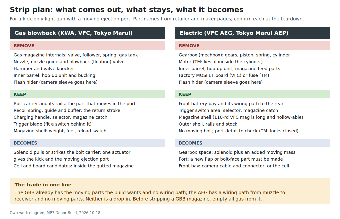
2.10 What has to come out
Gas donor. Empty the magazine of gas first: it stores liquefied propellant under pressure, and its valve should never be opened or the magazine dismantled while there is any left (Volume 3). Then remove the magazine’s internals (valve, follower, spring, gas reservoir); the nozzle, nozzle guide and blowback valve from the carrier; the hammer and valve knocker; the inner barrel, hop-up unit and bucking; and the flash hider. Keep the carrier, its guide rails, the recoil spring and guide, the buffer, the charging handle, the selector, the magazine catch and the trigger.
Electric donor. Remove the battery; the mechbox complete with motor; the inner barrel and hop-up; the factory MOSFET board or fuse; and the flash hider. Keep the front bay and its wiring path, the trigger area, the selector, the magazine catch and the magazine shell.
Keep everything. Bag and label every removed part. A donor that can be put back together is worth more if the build moves on to the printed shell, and some removed parts (springs, the carrier) may be needed as references for the printed version.
2.11 The teardown checklist
What to capture when each of the three donors is opened, with the instrument from the lab for each.
Table 7 — The teardown checklist
| # | Measurement or photo | Why | Instrument |
|---|---|---|---|
| 1 | The manual’s exploded diagram | Names and order of parts | Phone camera |
| 2 | Mass of the complete gun, with and without the magazine | Settles Volume 1’s three weights; the realism baseline | Scale |
| 3 | Mass after stripping | What the conversion costs in weight | Scale |
| 4 | Flash hider bore, outside diameter, length, thread | Camera sleeve design (§2.5) | Calipers, thread gauge |
| 5 | Front cap internal envelope | Camera cable and connector; battery on an electric donor | Calipers |
| 6 | Bolt carrier mass, length and travel | Solenoid sizing, concept A (§2.6) | Scale, calipers |
| 7 | Recoil spring free length and force at two compressions | Solenoid sizing | Calipers, force gauge or luggage scale |
| 8 | Upper receiver void with the gas parts out, length × width × height | Solenoid and board space | Calipers |
| 9 | Magazine internal cavity once gutted: inside depth front to back, inside width, length | Board on edge (§2.8), cable route and clamp (§2.7) | Calipers |
| 10 | Whether the top rail sits over a void | Cable path | Remove rail, look |
| 11 | Trigger travel and the space behind the blade | Trigger switch | Calipers |
| 12 | Every internal face, photographed square-on with a ruler | The printed-shell dive will need them | Phone camera, ruler |
| 13 | Magazine base plate: width, length, thickness, material, how it is retained | Gland or panel connector (§2.7) | Calipers |
| 14 | Magazine well: clearance around the magazine, what is above the well top, and how the catch engages | Cable route and the service connector (§2.7) | Calipers, look |
| 15 | Ejection port opening, length × height, and how much of the carrier’s travel shows in it | Port concepts A and B (§2.6) | Calipers, phone video |
| 16 | A 21 × 51 mm Pico dummy in each candidate location | Board placement (§2.8) | Printed dummy, ruler |
The checklist is run on all three donors, and the numbers fill the scorecard in Volume 1 §1.10. They become the next volume, the teardown, written from what is actually inside.
2.12 What could not be verified
- Any internal dimension of any airsoft MP7. None is published.
- The KWA and VFC gas guns’ takedown and internal layout. The public teardown is of the Tokyo Marui gun only.
- The VFC electric’s gearbox layout and the size of its front bay.
- The Tokyo Marui electric’s battery bay, inferred from photographs and the VFC evidence.
- Whether a solenoid that fits can move the carrier against its spring fast enough to feel like a shot (concept A), and whether a second coil’s heat is acceptable (concept B). The build’s first bench tests.
- What is inside each magazine, whether a 21 mm-wide board fits on edge, and how wide the base plates are.
- The Pico’s overall height with its parts and socket; the text of its datasheet gives only the 1 mm PCB.
- The MP7’s cyclic rate (about 950 rounds a minute) is from a press report of an H&K figure, not from H&K’s own page.
- GX16 connector ratings, which only sellers publish, and the magnetic connector’s current rating.
- The two teardown sources’ authors and dates. The French club blog gives neither; it also describes the Tokyo Marui gas magazine as an “M4 MWS” type, which looks like an error, so its details are used only where they agree with Tokyo Marui’s page.
Sources
Footnotes
-
Tokyo Marui, “MP7A1 ブラック — ガスブローバック マシンガン”, https://www.tokyo-marui.co.jp/products/gas/machinegun/281, accessed 2026-10-18. ↩ ↩2 ↩3
-
Tir Sportif Chabris, “Le MP7 Marui GBBR : analyse des pièces et améliorations”, https://tirsportifchabris.fr/blog/eclate-mp7-marui-gbbr, accessed 2026-10-18. Club blog; author and date not given. ↩ ↩2
-
Airsoft Station, “H&K MP7 Green Gas Blowback Airsoft Rifle by KWA”, UX-2279020, https://airsoftstation.com/h-k-mp7a1-gas-blowback-airsoft-gun-by-kwa/, accessed 2026-10-18. ↩
-
Fox Airsoft, “Elite Force MP7 AEG in-depth review”, https://www.foxairsoft.com/blog/elite-force-mp7-aeg-indepth-review-fox-airsoft/, and the Elite Force listing, as summarised in search results, 2026-10-18. ↩
-
Tokyo Marui, “MP7A1 ブラック — 電動コンパクトマシンガン”, https://www.tokyo-marui.co.jp/products/electric/compact/404, accessed 2026-10-18. ↩
-
Giant Suzuki (ジャイアン鈴木), “Middle-aged airsoft” series, part 5, on tuning the Tokyo Marui MP7A1 electric, Weekly ASCII, updated 21 April 2023, https://weekly.ascii.jp/elem/000/004/129/4129146/, accessed 2026-10-18. ↩ ↩2
-
Tir Sportif Chabris, “Fonctionnement et optimisation de la gearbox du MP7 Marui”, https://tirsportifchabris.fr/blog/gearbox-pour-mp7-marui, accessed 2026-10-18. Club blog; author and date not given. ↩
-
Airsoft Station, “VFC H&K MP7 SMG AEG Airsoft Rifle, Black”, UX-2262070, https://airsoftstation.com/vfc-h-k-mp7-smg-aeg-airsoft-rifle-black/, accessed 2026-10-18. ↩
-
Airsoft GI, “Elite Force H&K MP7 AEG Airsoft SMG by VFC (Black)”, HK-2262070, https://www.airsoftgi.com/product/Elite-Force-HK-MP7-AEG-Airsoft-SMG-BY-VFC-Black-39731/, accessed 2026-10-18; VFC MP7 AEG piston listing (Atom Airsoft), as summarised in search results. ↩
-
DFRobot, “Gravity: IR Positioning Camera For Arduino”, SEN0158, https://www.dfrobot.com/product-1088.html, accessed 2026-10-18. ↩
-
Patrol Base, “WELL R-4 SMG-7 AEP”, https://www.patrolbase.co.uk/well-mp7-a1-r-4, accessed 2026-10-18 (outer barrel thread 12 mm, counter-clockwise). ↩
-
Redwolf Airsoft, “Nine Ball Silencer Adapter S.A.S Neo for Tokyo Marui MP7A1 AEG / GBB series (12mm CCW to 14mm CCW)”, https://www.redwolfairsoft.com/nine-ball-silencer-adapter-s-a-s-neo-for-tokyo-marui-mp7a1-aeg-gbb-series-12mm-ccw-to-14mm-ccw.html, as listed on 2026-10-18. ↩
-
Army Recognition, “Lithuania receives MP7 A2 submachine guns from German company Heckler & Koch”, 2024, https://armyrecognition.com/news/army-news/army-news-2024/lithuania-receives-mp7-a2-submachine-guns-from-german-company-heckler-koch, as summarised in search results, 2026-10-18 (950 rounds per minute). Secondary; the HK MP7 dive owns the real gun’s figures. ↩
-
Adafruit, “Micro servo - TowerPro SG92R”, product 169, https://www.adafruit.com/product/169, accessed 2026-10-18 ($5.95; 0.1 s/60° at 4.8 V; 2.5 kg-cm; 23 × 11 × 29 mm; 9 g). ↩
-
Airsoft GI, “Elite Force H&K MP7 GBB Airsoft SMG by KWA (Black)”, item 5635, https://www.airsoftgi.com/product/Elite-Force-HK-MP7-GBB-Airsoft-SMG-by-KWA-Black-5635/, accessed 2026-10-18; magazine description from a customer review (V. Moore, 2019) on that page, not from the maker. ↩
-
Umarex USA, “HK MP7 Magazine - 40 rds - Black”, SKU 2279021, https://www.umarexusa.com/hk-mp7-magazine-40-rds-black, and Airsoft GI, “Elite Force H&K MP7 by KWA 40 rd. Gas Magazine (Black)”, HK-MAG-2279021, https://www.airsoftgi.com/product/Elite-Force-HK-MP7-by-KWA-40-rd-Gas-Magazine-Black-5881/, both $74.99, accessed 2026-10-18. Airsoft GI’s description says 48 rounds against 40 in its own specifications; Umarex says 40. Umarex names rebuild kit 2211110 for this magazine. ↩
-
John Yan, “Blamcon Light Guns”, Gaming Nexus, 1 October 2025, https://www.gamingnexus.com/Article/16263/Blamcon-Light-Guns/, accessed 2026-10-18. ↩
-
Adafruit, “USB C Small Round Panel Mount Extension Cable”, product 6069, https://www.adafruit.com/product/6069, accessed 2026-10-18 ($4.50; “fit holes 12mm to 18mm”). ↩
-
Adafruit, “USB C Round Panel Mount Extension Cable”, product 4218, https://www.adafruit.com/product/4218, accessed 2026-10-18 ($9.95, 30 cm; “fit holes 21.5mm to ~27mm”). ↩
-
Adafruit, “DIY Magnetic Connector - Right Angle Four Contact Pins”, product 5358, https://www.adafruit.com/product/5358, accessed 2026-10-18 ($6.50; no current rating on the page). Botland’s listing of the same part gives 2 A and 36 V, unconfirmed. ↩
-
Raspberry Pi, Raspberry Pi Pico product brief, https://datasheets.raspberrypi.com/pico/pico-product-brief.pdf (“21 mm × 51 mm”), and Raspberry Pi Pico 2 datasheet, https://pip-assets.raspberrypi.com/categories/1005-raspberry-pi-pico-2/documents/RP-008299-DS-3-pico-2-datasheet.pdf (“40 pin 21×51 ‘DIP’ style 1mm thick PCB”), as quoted in search results, 2026-10-18. ↩
Comments (0)