Sterling Mk 7 Para Pistol · Volume 3
How It Works, and How to Keep It Working: The Mark 7 Read Through Sterling's Own Handbook
The blowback cycle, the A-series trigger mechanism and the little that is published about the closed-bolt C series, field stripping, the armourer's detail strip, zeroing, cleaning, wear and repair, all from the Sterling Mark 4 User Handbook that the US dealer shipped with new Mark 7s, with every point where the Mark 7 departs from it marked
3.1 Which manual, and why
Sterling printed a handbook for each Mark 7 series. A US dealer’s price list of 2001 offered a “Mk7A User Manual (SMG)” and a “Mk7C User Manual (semi-auto pistol)” at $25 each, and the C4 that Rock Island Auction sold in 2010 came “with user handbook”.12 Neither handbook was found online or in any library catalogue searched for this dive.
What was found is the company’s User Handbook for the Mark 4 sub-machine gun, the military L2A3, in the edition that carries Sterling’s “Brief history” signed DTEH 1984, the same document that defines the Mark 7 (Volume 1).3 There are two reasons to read the Mark 7 through it. First, the A-series Mark 7 is a Mark 4 internally: the dealer that sold new Mark 7s lists the Mark 4 trigger group, return springs and, for the A8, the Mark 4 bolt as Mark 7 parts (next section).1 Second, that dealer shipped every new A4 and A8 “Complete with rare 15rd mag and Mk4 user manual”.4 In practice the Mark 4 handbook was the Mark 7 A-series manual.
It does not cover the C series. The C4 and C8 use a different bolt and a different trigger group, and no Sterling text describing them was found. Where this volume reaches the C series it says what is known, says what is not, and does not fill the gap from memory.
Every quotation below is from the handbook unless another source is given. The scan is a poor photocopy with damaged OCR, so the quotations were checked against the page images. Paragraph numbers are the handbook’s.
3.2 What the Mark 7 shares with the Mark 4
The parts list of PS Arms of Easton, Pennsylvania, which sold Sterling guns, parts and manuals from about 2001 to 2009, is the only published parts-commonality statement found. It is a dealer’s catalogue, so it records what the dealer sold as fitting, not a factory drawing list.1
Table 1 — What the Mark 7 shares with the Mark 4
| Part | Fits, per the dealer’s 2004 list | What follows |
|---|---|---|
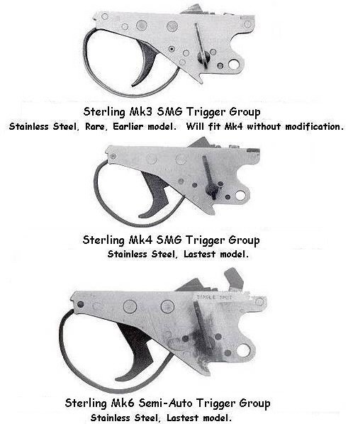
| Trigger group, Mark 4 | ”also fits Mk3, Mk5, Mk7A” | A-series trigger mechanism = Mark 4 (described below) |
| Trigger group, Mark 6 | ”Mk6, Mk7C, Mk8” | C-series trigger mechanism = Mark 6 semi-automatic |
| Bolt with extractor | ”Mk7A8 (same as Mk4)“ | A8 bolt = Mark 4 bolt |
| Bolt assembly with extractor, firing pin and firing pin spring | ”Mk6, Mk7C, Mk8” | C-series bolt carries a separate, sprung firing pin |
| Firing pin block | ”Mk6, Mk7C, Mk8” | a C-series part with no Mark 4 equivalent |
| Recoil springs and cup | ”Mk4, Mk5, Mk7A” | A-series return spring = Mark 4 |
| Rear end cap | Mk7A4 “has buffer to reduce impact on locking lugs”; a second cap for “Mk7A8, Mk7C4, Mk7C8” | the A4 alone has a buffered back cap |
| Barrel | ”Barrel 4” or 8”, Mk7 (British proof marks)”; barrel nut listed separately | the Mark 7 barrel is held by a nut, not the Mark 4’s screws |
| Foregrip strap | ”Mk7” | Mark 7 only |
Two things in that table matter for the rest of this volume. The A4 bolt is not listed as identical to the Mark 4’s; only the A8 bolt is. Whether the A4’s differs, and how, was not found. And the Mark 7’s barrel retention differs from the Mark 4’s, so the handbook’s barrel-removal paragraph does not apply to it (see “The armourer’s detail strip”).
3.3 The cycle of operation
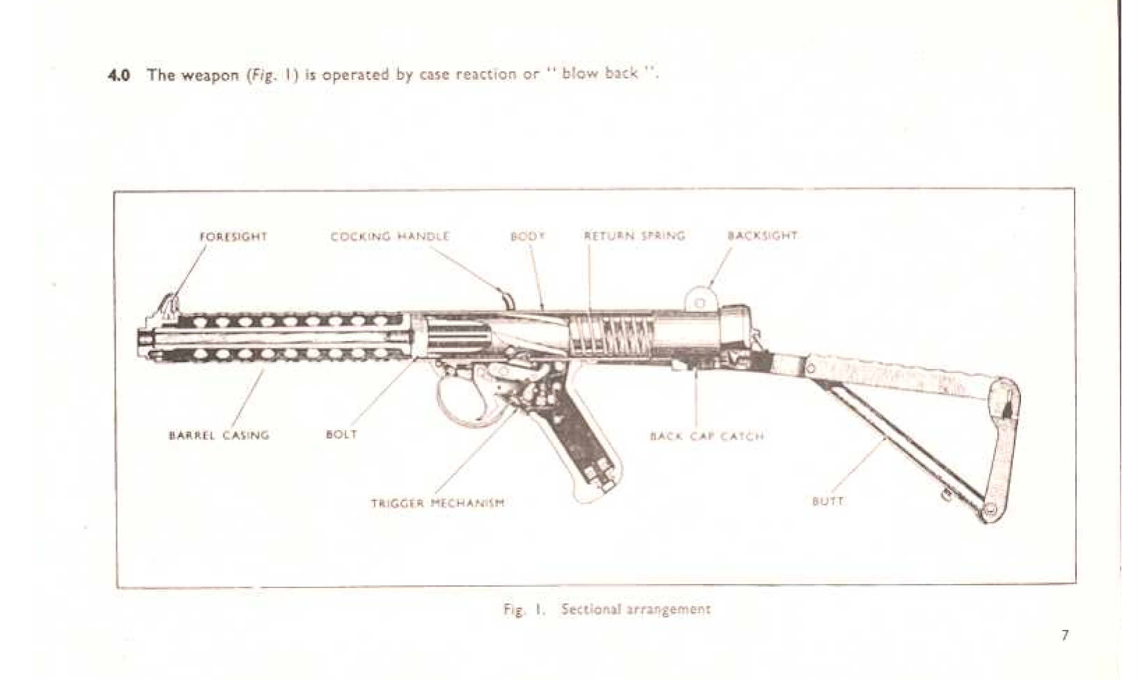
The Sterling is a straight blowback. The handbook says it “is operated by case reaction or ‘blow back’” whether fired “single shot or in bursts” (paras 1.0 and 4.0). There is no lock. The bolt’s mass and the return spring are the only things holding the case in the chamber.
Backward action (para 4.1, Fig. 2). On firing, the propellant gases push equally on the bullet and on the case, and the case is “supported by the bolt and the compression of the return spring”. Because the bullet weighs far less than case and bolt together, it reaches a much higher velocity. In the handbook’s words: “When the bullet clears the muzzle all have reached their maximum velocities but the cartridge case has not yet cleared from the chamber, thus preventing the gases escaping from the breech. The cartridge case does not clear the breech until the gases behind the bullet have dispersed into the air, ensuring that pressures are down to safe limits before the breech is unsealed.” The return spring then decelerates the bolt. The empty case, “held against the face of the bolt by the extractor, is carried back until it strikes the ejector and is ejected through the opening on the right side of the weapon.”
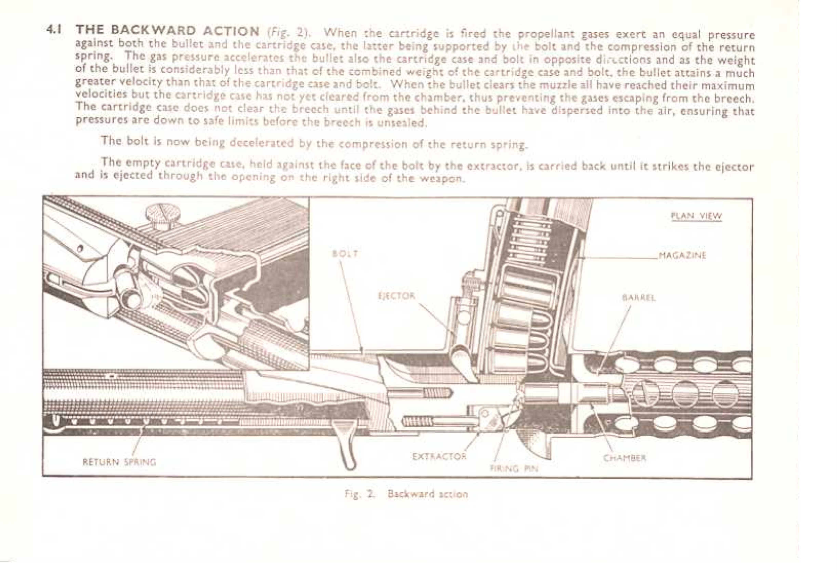
That paragraph’s argument holds for the Mark 4’s 7.8-inch barrel. The A4 and C4 fire the same cartridge from a barrel of about 4 inches (Volume 2), so the bullet leaves sooner and the bolt has moved less when it does. Sterling’s own account of how the bolt mass and spring were matched to the short barrel, if one was written, is not in any document found. The dealer’s note that the A4 alone has a back cap with a buffer “to reduce impact on locking lugs” is the only published hint that the short gun’s bolt arrives at the back cap harder than the Mark 4’s.1 The Sterling bolt has no locking lugs, so the lugs meant are presumably the back cap’s own, which lock the cap into the body (para 8.1). The dealer does not say.
Forward action (para 4.2, Fig. 3). “When the bolt reaches the limit of its backward travel it is forced forward by the compression of the return spring. During its forward travel the bolt contacts the top round in the magazine and, guided by the magazine lips, the round is fed into the chamber. The bolt then follows up on the round, feeds it into the chamber, and fires it just before the forward movement ceases.” The emphasis on just is the handbook’s own italic. Firing while the bolt is still moving forward means part of the bolt’s momentum is spent against the start of the recoil impulse. The handbook then gives what it calls the mechanical safety of the design: “During the forward movement of the round from the magazine, the firing pin of the bolt cannot come into line with the percussion cap of the cartridge until the round is actually in the chamber.”
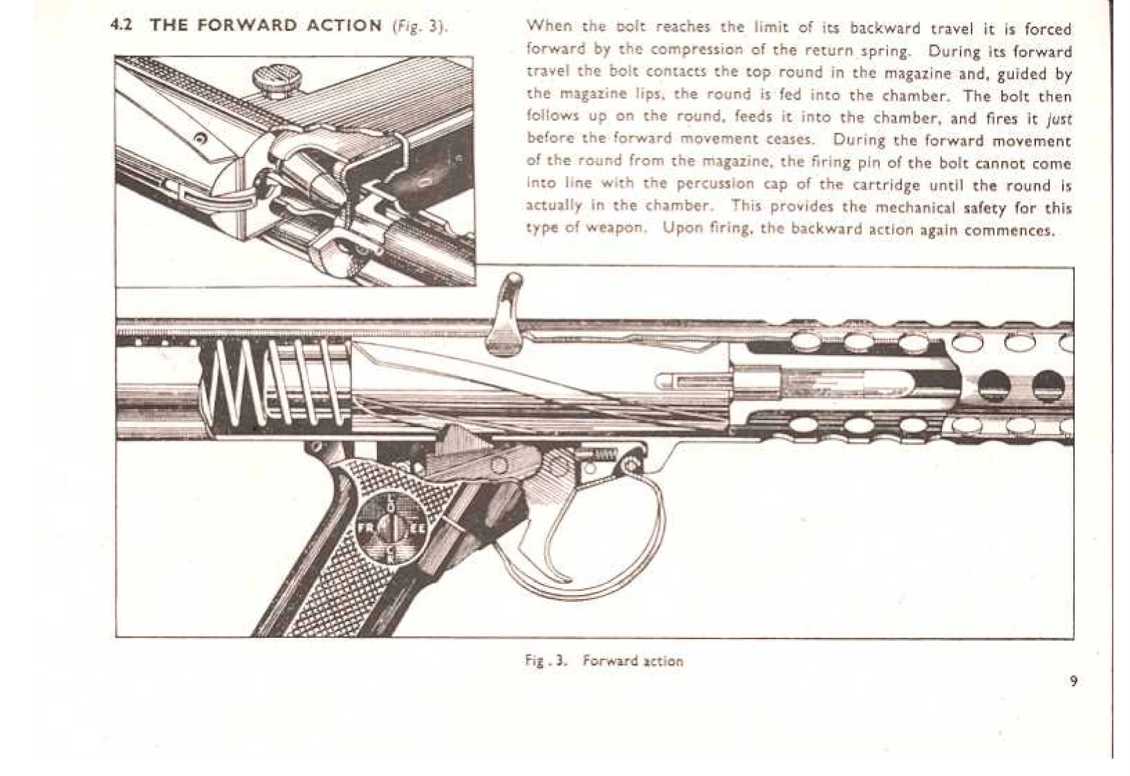
The handbook describes the firing pin as part of the bolt (“the firing pin of the bolt”) and treats it as fixed. That is the A series’ arrangement. In the C series the firing pin is a separate part in the bolt, with its own spring.13
Three further features are visible in the handbook’s drawings and described in other sources:
- Side feed. The magazine enters from the left and the empty case leaves to the right (Fig. 2). This is why a Sterling is carried with the magazine sticking out sideways, and why the twin-stacked magazines of Volume 2 could be built at all.
- Whether the cocking handle moves with the bolt. The handbook’s stripping paragraph has the cocking handle passing through the hole in the centre pin of the return-spring assembly (para 8.1), and Fig. 3 shows the handle at the front of the body with the bolt forward. The handbook does not say in words whether the handle reciprocates in firing. That was not confirmed, and it is left as a question rather than stated.
- Ribs on the bolt. The bolt in Figs. 2 and 3 carries raised helical ribs along its length. The handbook does not explain them. Their usual explanation, that they clear dirt from the body, is common in secondary writing but was not found in a Sterling text, so it is not asserted here.
The handbook gives the Mark 4’s cyclic rate as “550 r.p.m. approx.” The dealer copy for the Mark 7 A series gives “560 rounds per minute” (Volume 2).34
3.4 The A-series trigger mechanism
The A4 and A8 use the Mark 4 trigger group, by the dealer’s parts list, and fire from an open bolt.14 The handbook describes that group in section 5, with the change lever at three positions: R for single shot, A for automatic and S for safe. The numbers in parentheses are the handbook’s own part numbers in its figures.
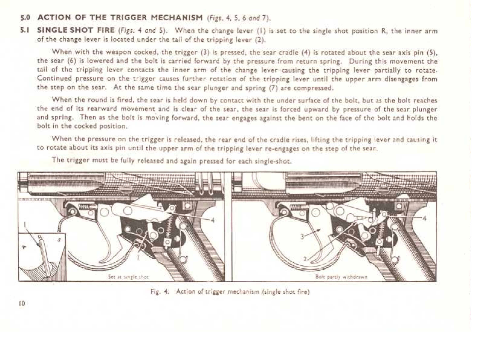
Single shot (para 5.1, Figs. 4 and 5). With the lever at R, its inner arm sits under the tail of the tripping lever (2). With the gun cocked, pressing the trigger (3) rotates the sear cradle (4) about the sear axis pin (5), the sear (6) drops, and the return spring drives the bolt forward. As the trigger moves, the tail of the tripping lever meets the change lever’s inner arm and the tripping lever rotates until its upper arm leaves the step on the sear. The sear plunger and spring (7) are compressed. While the bolt is moving, its underside holds the sear down. When the bolt reaches the rear and is clear of the sear, the plunger pushes the sear up, and as the bolt comes forward again “the sear engages against the bent on the face of the bolt and holds the bolt in the cocked position.” Releasing the trigger lets the cradle rise and the tripping lever re-engage the sear step. “The trigger must be fully released and again pressed for each single-shot.”
Automatic (para 5.2, Fig. 6). With the lever at A, a projection on the upper part of the trigger lifts the end of the sear cradle, which depresses the sear and frees the bolt. “The weapon will now continue firing until either the trigger is released or the magazine is empty.” On release, the sear-cradle spring (8) returns the cradle and the sear rises into the boltway to catch the bent.
Safe (para 5.3, Fig. 7). At S, the change lever’s inner arm sits directly under the short arm of the tripping lever, so the cradle and sear cannot be depressed when the trigger is pressed. With the bolt forward and the lever at S, “the weapon cannot be cocked because the sear (6) is engaged in the safety slot (9) at the rear of the bolt”. Para 3.3 sums it up: the SAFE position “locks the trigger and sear, irrespective of the position of the bolt, which eliminates the possibility of a round being fired if the weapon is dropped.”
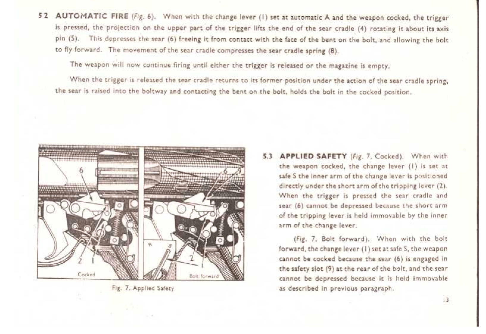
One consequence of the open bolt is worth stating plainly. A cocked A-series Mark 7 with a loaded magazine has its bolt held back on the sear and the chamber empty. If the sear lets go, the bolt runs forward, chambers and fires. The handbook’s answer is the S position, which holds the sear whether the bolt is back or forward. The dropped-gun sentence in para 3.3 refers to this.
3.5 The C series: closed bolt, floating firing pin
Sterling’s description of the C series is two sentences long: “The C series fires from a closed bolt and has a floating firing pin. All closed bolt units fire in the single shot mode only.”3 Its account of the Mark 6 carbine, which shares the C series’ bolt and trigger group by the dealer’s list, adds only that the Mark 6 was made “to conform with U.S. Regulations” and fires “semi-automatic only”.31
From the dealer’s parts list and photographs, and from the RIA lot, the following can be stated:
- The C-series bolt carries a separate firing pin and firing-pin spring, and the gun has a firing pin block. Both are Mark 6 parts.1
- The C-series trigger group is the Mark 6 semi-automatic group. The dealer’s photograph shows it stamped “SINGLE SHOT”, and it is visibly a different pressing from the Mark 3 and Mark 4 groups.5
- The RIA C4’s change lever has two positions, FIRE and SAFE (Volume 2).2
What is not published anywhere found: how the C-series firing pin is struck (hammer, striker or other), what the firing pin block does and when, how the group disconnects between shots, and the C-series stripping sequence. The open-and-closed schematic below therefore draws the C series only to the level of the maker’s two sentences. Anyone working on a C4 or C8 needs Sterling’s Mk7C handbook, which was offered for sale in 2001 and has not been found since.1
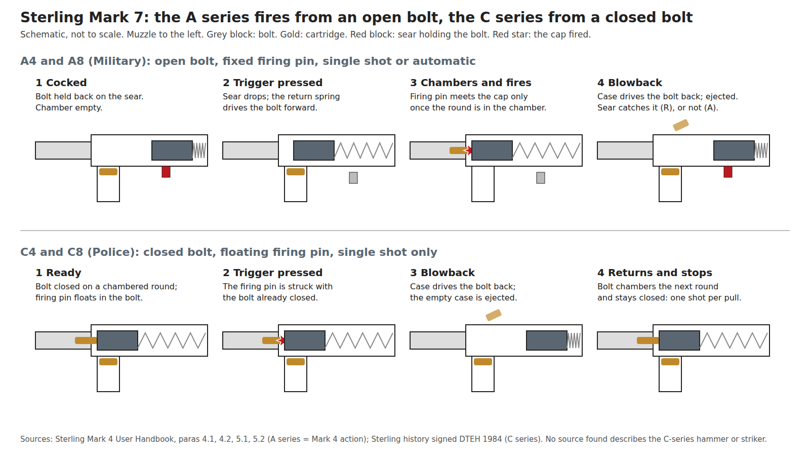
The difference between the two series is the difference ATF’s rulings of 1982 and 1983 turn on. That is the subject of Volume 4.
3.6 Field stripping
The handbook calls field stripping “elementary stripping” (section 3, para 8.0). It is the user’s level: return spring and bolt, then the trigger group. Everything beyond it is for an armourer. The sequence below is the handbook’s, followed by the points at which a Mark 7 differs.
Before stripping (para 8.0). “Before stripping, ensure that the weapon is not loaded and remove sling if fitted. Set change lever to A, place butt in the folded position and bolt forward.” The handbook does not spell out its unloading drill in this paragraph. On any open-bolt gun, “not loaded” has to mean the magazine removed first and the chamber and boltway then checked with the bolt drawn back, because a cocked open-bolt gun with a magazine in it fires when the bolt is released.
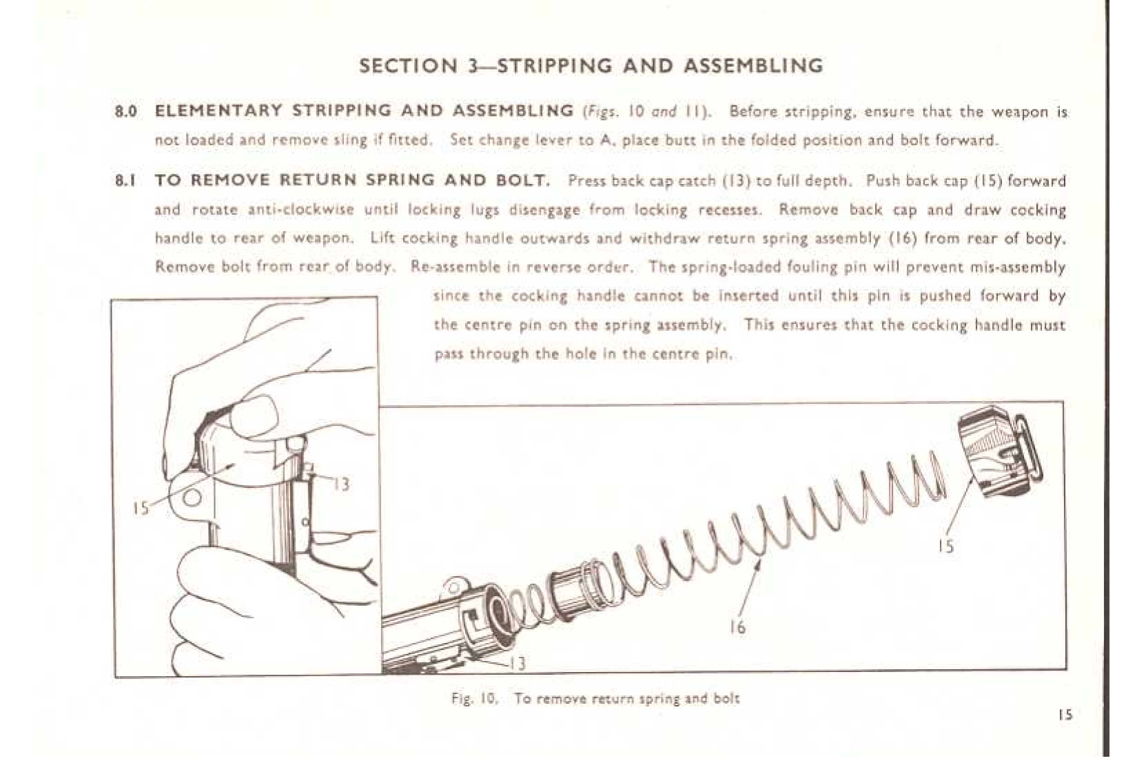
Return spring and bolt (para 8.1, Fig. 10).
- Press the back cap catch (13) to full depth.
- Push the back cap (15) forward and rotate it anticlockwise until its locking lugs come out of the locking recesses. Remove the back cap.
- Draw the cocking handle to the rear of the body, lift it outwards, and withdraw the return-spring assembly (16) from the rear of the body.
- Remove the bolt from the rear of the body.
Reassemble in reverse order. The handbook adds a guard against error: “The spring-loaded fouling pin will prevent mis-assembly since the cocking handle cannot be inserted until this pin is pushed forward by the centre pin on the spring assembly. This ensures that the cocking handle must pass through the hole in the centre pin.”
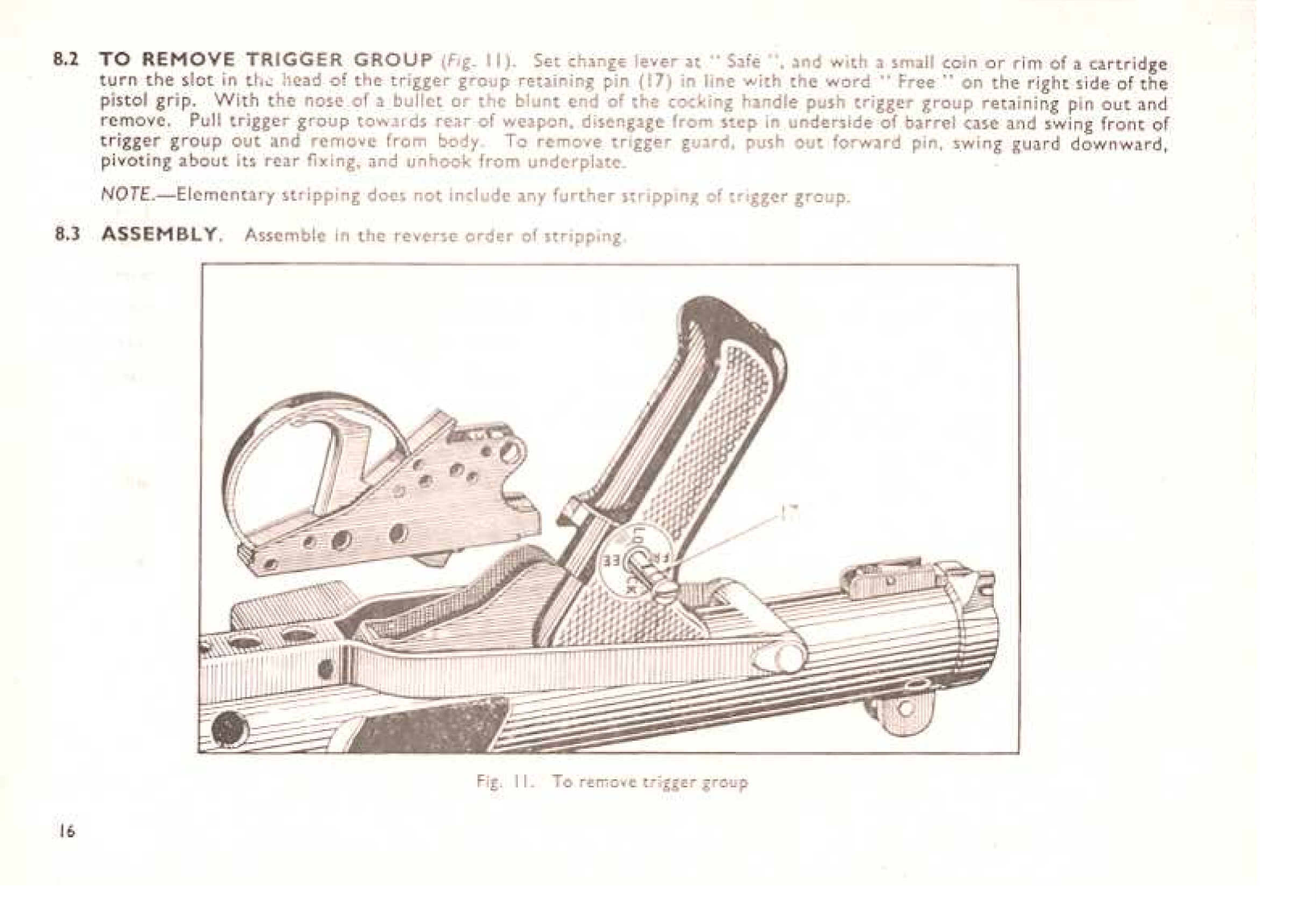
Trigger group (para 8.2, Fig. 11).
- Set the change lever to Safe.
- With a small coin or the rim of a cartridge, turn the slot in the head of the trigger-group retaining pin (17) in line with the word “Free” on the right side of the pistol grip.
- With the nose of a bullet or the blunt end of the cocking handle, push the retaining pin out and remove it.
- Pull the trigger group towards the rear, disengage it from the step in the underside of the barrel casing, swing its front out and remove it from the body.
- To remove the trigger guard, push out the forward pin, swing the guard down about its rear fixing and unhook it from the underplate.
“Elementary stripping does not include any further stripping of trigger group.” Assembly is “in the reverse order of stripping” (para 8.3).
Where a Mark 7 differs from the handbook.
- No butt. The step “place butt in the folded position” does not apply. A Mark 7 with Sterling’s optional plastic butt has it mounted on a special end cap, held by “a spring retained locking pin” (Volume 2).6 Whether that end cap comes off with the butt fitted was not found. Remove the butt first; it is a separate part.
- The A4’s back cap is buffered. The dealer lists a separate A4 back cap “has buffer to reduce impact on locking lugs”.1 Its fitting and removal are presumably the same as the standard cap’s, but no source describes them.
- The C series has no A position. The handbook’s first step sets the lever to A. A C4 or C8 has only FIRE and SAFE (Volume 2), and its bolt carries a separate firing pin and spring that the handbook’s para 8.1 does not mention. The C-series sequence is in Sterling’s Mk7C handbook, which was not found. The steps above are the Mark 4’s. Applying them to a C-series gun is an assumption that the outer parts (back cap, return spring, cocking handle and trigger-group retaining pin) are shared. The dealer’s list supports that for the back cap and does not address the rest.
- The foregrip. The A series’ vertical foregrip is held by a strap (“Foregrip Strap, Mk7”) and, on the dealer’s reproduction, “with screw and mounting plate”.1 It does not have to come off for elementary stripping. The handbook does not mention it.
3.7 The armourer’s detail strip
The handbook’s section 9, “Advanced stripping and assembly”, opens with a restriction. The OCR of the sentence is damaged, but its sense is plain on the page image: this stripping is done by an armourer, when worn or broken parts are to be replaced. What it covers is summarised here so that an owner knows what each operation involves and which ones are a gunsmith’s work. Paragraph numbers are the handbook’s.
Table 2 — The armourer's detail strip
| Para | Operation | What the handbook says about it |
|---|---|---|
| 9.1 | Ejector | Unscrew the magazine-catch screw and remove its spring and the magazine catch, then the ejector retaining screw. Tap the ejector out “through ejection opening”. |
| 9.2 | Trigger group | Pins out in order, the sear group lifted out of the trigger group. Armourer’s work. Reassembly (9.9) ends with a function test “at safe, single-shot and automatic”. |
| 9.3 | Extractor | Push out the extractor retaining pin and remove the extractor. “During this operation hold extractor with thumb or forefinger otherwise it may shoot out.” Then the extractor plunger and spring. |
| 9.4 | Pistol grip | Unscrew the grip retaining screw with an Allen key and withdraw the grip. |
| 9.5 | Barrel (Mark 4 only) | Partly unscrew the two barrel-retaining screws (28) with an Allen key, protect them with a piece of wood and drive the barrel back from its seating with a mallet, then remove the screws, rotate the barrel to clear the bayonet lug and withdraw it. |
| 9.6 | Magazine | Depress the stud through the bottom plate, slide the plate off “controlling the magazine spring with hand to prevent it flying free”, and withdraw the platform and spring, rocking the platform past the indentations at the bottom of the case. |
| 9.7 | Foresight | A spring fit in a dovetail on the barrel casing, “there being no retaining pin or screw”. Drift it out to either side. |
| 9.8 | Backsight | ”This should not be removed unless absolutely necessary.” Drive out the pin and lift out sight and spring, “taking care not to lose small collars”. |
The reassembly notes include three that are easy to get wrong:
- Barrel orientation (para 9.10). On the Mark 4, the extractor clearance groove in the barrel face “should be in line with the ejector opening”, and the two retaining screws go in hand tight and are then tightened “a little on each screw at a time”.
- Magazine (para 9.13). Feed the platform and spring in, rocking past the indentations, so that “the upper roller is on the left side when viewed from the rear of the magazine”.
- Backsight (para 9.12). The pin is peened over into countersinks in the collars. Replacing it is a staking job, not a push fit.
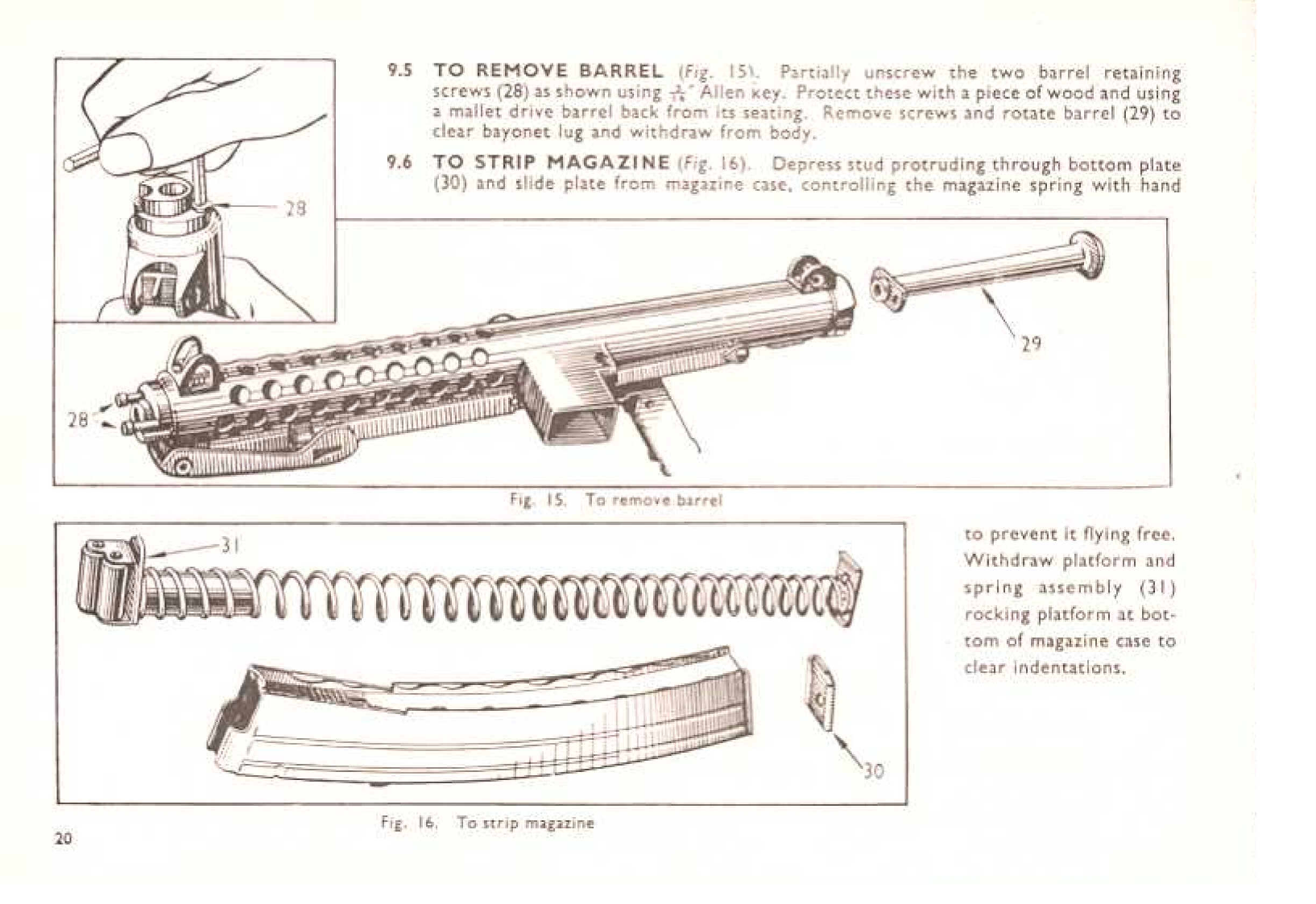
The Mark 7 barrel. The dealer lists a “Barrel 4” or 8”, Mk7 (British proof marks)” and a separate barrel nut, and the photographs in Volume 2 show a knurled nut at the front of the short casing.1 No source describes how the Mark 7 barrel is removed, what holds it in alignment with the ejector opening, or whether the nut is the silencer mount. The handbook’s para 9.5 is not a substitute. A Mark 7 barrel that needs to come out is a job for someone with the Mk7A or Mk7C handbook, or a gunsmith who knows the gun.
The Allen key size for paras 9.4 and 9.5 is printed in the handbook as a fraction, but the scan does not render it legibly. It is not given here.
3.8 Sights and zeroing
The Mark 4 has a rear aperture that is “instantly changed from 100 to 200 yards range setting by rocking over” (para 3.4), and a foresight on the barrel casing. Its sight radius is 16.1 inches.3 The Mark 7 keeps a foresight on its short casing and the rear sight on the body (photographs in Volume 2), so its sight radius is much shorter. No figure for the Mark 7’s sight radius or its rear-sight markings was found. Whether the Mark 7 keeps the 100 and 200-yard flip, which would be optimistic on a 4-inch pistol, is not recorded.
The handbook’s zeroing method (section 4) applies in principle:
- The gun “is zeroed before issue to the user and should require little attention other than correction for line or direction” (para 10.0).
- Windage is corrected by tapping the foresight left or right in its dovetail. It “is a spring fit in its slide and requires no securing screw.”
- Elevation is corrected by loosening the BA grub screw that secures the foresight blade, with an Allen key, and rotating the blade in or out “one or more full turns”, then re-tightening the grub screw (para 10.1). The handbook gives the change in point of impact for one turn of the blade at 100 yards, but the figure is not legible in the scan.
- The Mark 4 is zeroed “at either 100 yards or 100 feet. For 100 yards the Mean Point of Impact should be on sight line. For 100 feet M.P.I. should be 2 inches above sight line” (para 10.2).
Blue Press adds that Sterling made front sights in seven heights “for accurate sighting in at the factory”.7 Whether the Mark 7 used the same blades, and at what range Sterling zeroed a Mark 7, is not recorded.
3.9 Cleaning and lubrication
Section 5 of the handbook is the whole of Sterling’s published cleaning instruction (para 11.0):
- Carry out elementary stripping.
- Clean the bore with a pull-through and flannelette 4 inches by 2 inches. When it is clean, oil it with a fresh piece the same size.
- Clean and oil the chamber with flannelette on a piece of stick.
- Clean the rest of the gun with an oily rag, “particular attention being paid to the oiling of the face of the bolt, inside the body and to the ejector.”
Magazines “should be cleaned with an oily rag. Ensure that the platform is easy to move inside the magazine case” (para 11.1).
That is all. The handbook names no lubricant, gives no interval, and has no section on cleaning after firing as distinct from routine cleaning. Its three named points (bolt face, inside of the body, ejector) are the places the cycle described above depends on: the bolt face carries the extractor and meets the cartridge head, the bolt runs the length of the body, and every case is thrown out by the ejector.
For a Mark 7 the same instruction applies, with a shorter pull-through run through a 4 or 7.8-inch barrel. For a C-series gun, the separate firing pin and its channel in the bolt are additional parts the handbook does not cover. They are a place for fouling and oil to collect, and Sterling’s C-series instructions for them were not found.
3.10 Inspection, wear and repair
What Sterling published. The handbook contains no inspection schedule, no wear limits, no replacement intervals and no malfunction or immediate-action table. Its only statement on repair is the restriction at the head of section 9: advanced stripping is armourer’s work, done to replace worn or broken parts. A spares catalogue for the Mark 4 existed (16 pages, shown on the PS Arms manuals page), but it was not found as a scan.8 No wear or interval figure for any Sterling part is given in this dive, because none was found.
What the handbook’s text identifies as wearing or fragile. Reading the stripping instructions for what they warn about gives the following list. These are inferences from the handbook’s wording, not Sterling statements about wear.
Table 3 — Inspection, wear and repair
| Part | Why it matters | The handbook’s clue |
|---|---|---|
| Extractor, plunger and spring | holds the case to the bolt face until the ejector strikes it (para 4.1); a weak extractor leaves cases in the chamber | spring-loaded and “may shoot out” (para 9.3), so the spring and plunger are easily lost |
| Ejector | throws out every case | named in the cleaning instruction and removable on its own (paras 9.1, 11.0) |
| Magazine platform and spring | the bolt feeds from the magazine lips (para 4.2) | “Ensure that the platform is easy to move inside the magazine case” (para 11.1); the platform rocks past indentations and has a handed roller (paras 9.6, 9.13) |
| Sear, sear plunger and spring, tripping lever | hold the open bolt back and, at R, stop it after each shot | the handbook’s function test “at safe, single-shot and automatic” after any work on the group (para 9.9) |
| Return spring | drives the bolt forward and decelerates it on recoil (paras 4.1, 4.2) | the dealer sold “recoil springs and cup” as separate spares for the Mark 4, Mark 5 and Mark 7A1 |
| A4 back-cap buffer | absorbs the bolt’s impact at the rear of its travel on the short gun | a separate A4 part, “has buffer to reduce impact on locking lugs”1 |
What an owner can do and what needs an armourer. Sterling’s own line is the elementary/advanced division: return spring, bolt and trigger-group removal, cleaning and magazine care are the user’s. Ejector, extractor, trigger-group stripping, barrel and sights are the armourer’s. For an A-series gun the trigger group and the open bolt are the machine-gun parts. In the United States, work on them for a registered gun stays inside the rules described in Volume 4, and that volume also explains why A-series parts must never be in the same place as a C-series pistol.
Reliability. Blue Press says the Sterling sub-machine gun “has been tested in dirt, sand, mud, ice, snow and water” and calls it “the most reliable available” compared with the Uzi and MP5, without giving any test.7 That is a magazine’s opinion about the Mark 4, not a Mark 7 test record. No reliability data for the Mark 7 itself was found.
Parts availability. In 2001 and 2004 PS Arms listed new Sterling Mark 7 barrels, A4 and A8/C back caps, Mark 4 and Mark 6 trigger groups and bolts, magazines, foregrips and straps, and the Mark 7 plastic butt with spacers.1 That site is gone and its prices are 20 years old. No current dealer stocking Mark 7-specific parts (the short barrel, the buffered A4 back cap, the foregrip strap) was found. Mark 4 parts are common because some 400,000 Sterlings were made, by Blue Press’s estimate.7 The Mark 7-specific parts are not.
3.11 What could not be verified
- Sterling’s Mk7A and Mk7C user handbooks. Both existed (sold in 2001) and neither was found.
- The C-series firing mechanism: how the floating firing pin is struck, what the firing pin block does, how the group disconnects, and the C-series stripping sequence.
- Whether the A4 bolt differs from the Mark 4 and A8 bolt, which the dealer lists as identical to each other.
- How the Mark 7 barrel is retained, aligned and removed.
- The Mark 7’s sight radius, rear-sight markings and factory zero.
- Whether the Sterling cocking handle reciprocates with the bolt in firing, and what the ribs on the bolt are for, in a Sterling text.
- The Allen key size in paras 9.4 and 9.5 and the one-turn elevation figure in para 10.1, both illegible in the scan.
- Any Sterling wear limit, replacement interval or malfunction table, for any mark.
References
Footnotes
-
PS Arms price lists archived 2001-11-28 (https://web.archive.org/web/20011128130133/http://www.geocities.com:80/psarms/StgPriceList.htm) and 2004-03-27 (https://web.archive.org/web/20040327114749/http://www.geocities.com:80/psarms/SAPriceList.htm), accessed 2026-10-20. Dealer catalogue: parts compatibility as the dealer stated it. ↩ ↩2 ↩3 ↩4 ↩5 ↩6 ↩7 ↩8 ↩9 ↩10 ↩11 ↩12 ↩13 ↩14 ↩15
-
Rock Island Auction Company, 30 April 2010, lot 891, “Sterling Armament Ltd Mk 7 C4 Pistol 9 mm”, https://www.rockislandauction.com/detail/49/891/sterling-armament-ltd-mk-7-c4-pistol-9-mm (accessed 2026-10-20). ↩ ↩2
-
Sterling Armament Company Limited, User Handbook, Sterling Sub-Machine Gun 9-mm. Mk 4 (S.M.G. 9mm. L.2.A.3.), with “Brief history” and nomenclature table signed “DTEH 1984”. Scan at http://pdf.textfiles.com/manuals/FIREARMS/sterling_mk4_smg.pdf (accessed 2026-10-20). Sections 1 to 5 (paras 1.0 to 11.1) are quoted by paragraph number in the text; the history, with the Mark 6, Mark 7 and Mark 8 entries, is on PDF page 23. ↩ ↩2 ↩3 ↩4 ↩5 ↩6
-
PS Arms, flyer “Sterling Para Pistol 9mm M7 A4 & A8 Military Version”, archived 2009-10-27, https://web.archive.org/web/20091027104838/http://geocities.com/psarms/LinkedFiles/SAMk7.jpg (accessed 2026-10-20). ↩ ↩2 ↩3
-
PS Arms, trigger-group photographs, archived 2009-10-27, https://web.archive.org/web/20091027105004/http://geocities.com/psarms/LinkedFiles/SATriggerGrps.jpg (accessed 2026-10-20). ↩
-
PS Arms, flyer with plastic butt, archived 2009-10-27, https://web.archive.org/web/20091027104827/http://geocities.com/psarms/LinkedFiles/SAMk7S.jpg (accessed 2026-10-20). ↩
-
“The Sterling Submachine Gun”, Dillon Blue Press, August 2011, p. 41, https://dilloncdn.com/bluepress/Aug_11_classic_2.pdf (accessed 2026-10-20). Unsigned. ↩ ↩2 ↩3
-
PS Arms, “Original Sterling Manuals - New, unissued”, archived 2009-10-27, https://web.archive.org/web/20091027104835/http://geocities.com/psarms/LinkedFiles/SAManuals.jpg (accessed 2026-10-20 and 2026-10-24). Shows the Mark 4 user handbook (22 pages, 1973 and post-1973 covers), the Mark 4 spares catalogue (16 pages) and the Mark 5 user handbook (26 pages). ↩


Comments (0)